Loading ...
Loading ...
Loading ...
15
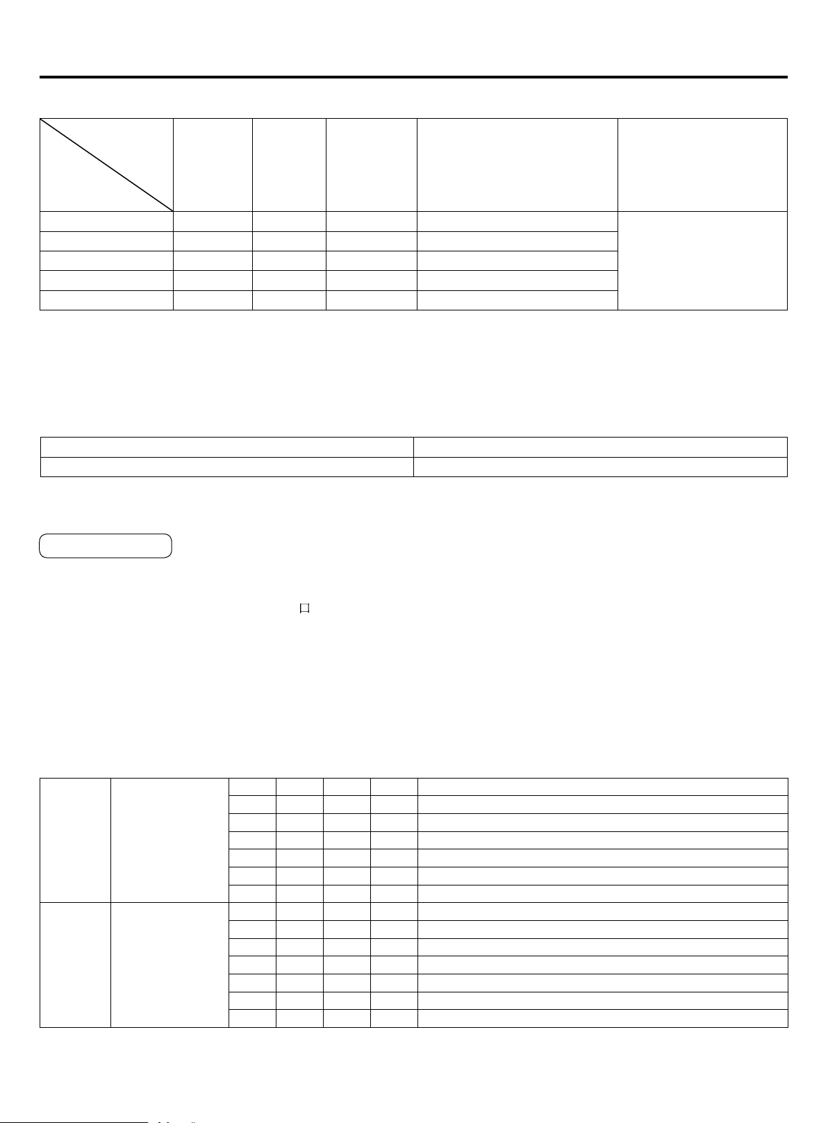
Wire gauge size and breaker size for total indoor amp draw. Current NEC guidelines and local codes will trump this chart.
Items
Total
Current of
Indoor Units(A)
Cross
Section
AWG
(mm
2
)
Length
in.(m)
Rated
Current of
Overow
Breaker(A)
Rated current of residual
Circuit Breaker(A)
Ground Fault Interrupter(mA)
Response time(S)
Cross Sectional
Area of Signal Line
<7 14(2.5) 65.6(20) 10 10 A,30 mA,0.1S or below
16 AWG (1.25mm
2
)
≥7 and <11 12(4) 65.6(20) 15 15 A,30 mA,0.1S or below
≥11and <16 10(6) 82(25) 20 20 A,30 mA,0.1S or below
≥16 and <22 8(8) 98.4(30) 30 30 A,30 mA,0.1S or below
≥22 and <27 6(10) 131(40) 30 30 A,30 mA,0.1S or below
• The electrical power line and signal lines must be tightened.
• Every indoor unit must have a ground connection.
• The power wire should be size up if it exceeds the permissible length.
• Shielding of the wire of all the indoor and outdoor units should be connected together and grounded at one point.
• Signal lines should not exceed 3280ft(1000m).
Electrical Wiring
• The shielding lay of the controller wire must be grounded at one end.
• The total length of the controller wire shall not be more than 820ft(250m).
Wired Controller ABC Chart
Length of Controller Wire ft (m) Wiring Dimensions AWG (mm
2
)
≤820(250) 18(0.75) x 3 core shielding line
Indoor Units PCB
In the following table, 1 represents On and 0 represents Off.
Denition principles of code switches:
SW01 is used to set wire controlled address of and set capabilities of master;SW03 is used to set indoor unit address
(combine original communication address and address of centralized controller)
Note : A wired controller can connected to at most sixteen ultrathin air-duct indoor units.
•The dipswitch is dialed to "On" position with the overline at the state of strapping if the code or overline status is “1” The
dipswitch is dialed to "Off"position with the overline at the state of disconnection if the code or overline status is "0"
• In the table below, the choice in the box "
" refers to the setting of the socket/overline before delivery.
SW01_1
SW01_2
SW01_3
SW01_4
Address of wire
controlled indoor
unit (group
address)
[1] [2] [3] [4] Address of wire controlled indoor unit (group address)
0 0 0 0 0# (wire controlled master unit) (default)
0 0 0 1 1# (wire controlled slave unit)
0 0 1 1 2# (wire controlled slave unit)
0 0 1 1 3# (wire controlled slave unit)
… … … … ……
1 1 1 1 15# (wire controlled slave unit)
SW01_5
SW01_6
SW01_7
SW01_8
Capability of
indoor unit
[5] [6] [7] [8] Capability of indoor unit
0 0 0 1 7000
0 0 1 0 9000
0 0 1 1 12000
0 1 1 0 18000
0 1 1 1 24000
1 0 0 1 30000
(A) Denition and description of SW01
SW01_1-4 is used to set indoor address when grouping multiple indoor units connected to single wired controller YR-
E16B or YR-E17.
SW01_5-8 set capacity of the indoor unit (factory set). Must only set when replacing board.
Dipswitch Setting
Loading ...
Loading ...
Loading ...