Loading ...
Loading ...
Loading ...
Page. 16
5. Adjust the burner’s control valve to LO to see that the
flame continues to wrap around the burner. Blow out
the flame, or use a quick fan motion from a writing
tablet or piece of cardboard to extinguish the flame,
and then observe the burner’s ability to reignite and
wrap around (also called “carry-over”) the burner
within several seconds. This flame “carry-over” is
essential for proper burner ignition and re-ignition.
6. Test re-ignition of the XLO and observe the carry-over
of the small simmer flames as the XLO system cycles
the burners on and off.
• If the low flame performance is not acceptable it
may be necessary to readjust the valve screw for a
STAR
®
burner that does not have sufficient carry-
over of the low flame. Turn the valve screw very
slightly counter-clockwise until carry-over of the
flame is acceptable. (See “Setting the STAR®
burner valve screws” on page 16.)
• If the burner flame is uneven, flutters, makes
excessive noise, or lifts, some of the slots in the
burner base may be blocked with food spillage or
other debris.
• Clogged slots can be cleared using a straightened
paper clip, needle, or similar object. Hard-to-
remove, encrusted food or debris can sometimes
be removed using a steel wool pad or fine wire
brush.
• Burner flames that are “lazy”, with excessively-
long flames, can be created by an incorrectly
fitted burner cap—from which many of the outer
mantles of the individual flames will tend to
“coalesce” or blend together. Verify that the
burner cap is seated properly on its burner base.
The cap should fit reasonably flat when correctly-
positioned on the base and not rock significantly.
7. Repeat the ignition and flame test procedures for
each rangetop STAR burner.
Setting the STAR
®
burner
valve screws
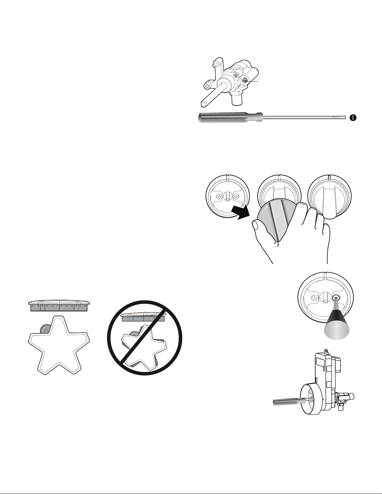
To set the burner valve screws
1. Remove the knob from the valve stem by slowly
pulling knob straight out, away from the control panel.
Correct burner cap Incorrect burner cap
Star
®
Star
®
A flat-head screwdriver with an
1/8" [3.0 mm] wide, .020"
[0.50 mm] thickness tip
(included) is used to adjust the
valve screws.
2. Remove the bezel-mounting
screw located to the right of
the valve stem, using a T-20
torx screwdriver.
3. Insert included 1/8''
flat-blade
screwdriver into the
hole of the bezel
mounting screw.
Access to the valve
screws through the
clearance hole in the
spark module. You
should feel the
engagement of the
screwdriver and the
valve screw.
Loading ...
Loading ...
Loading ...