Loading ...
Loading ...
Loading ...
1 Product Introduction D-Link Smart Managed Switch User Manual
5
5
Front Panel
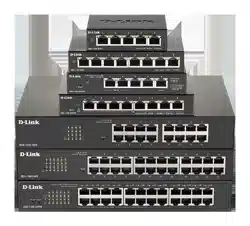
Figure 1.7 – DGS-1100-08P Front Panel
Power LED: The Power LED lights up when the Switch is connected to a power source.
Reset: Press the Reset button for 1 to 5 seconds to reboot the Switch. Press the Reset button for 6 to10
seconds to reset the Switch back to the default settings. The LED will light up solid amber for 2 seconds.
When pressing the Reset button for longer than 10 seconds, the device will enter loader mode and the LED
will light up solid green for 2 seconds. If the device cannot reboot, it will automatically enter loader mode.
Alternatively, you can press Reset to power up the device and enter loader mode.
Link/Act/Speed LED (Ports 1-8):
Flashing: Indicates a network link through the corresponding port.
Blinking: Indicates that the Switch is either sending or receiving data to the port.
Green: Indicates that the port is running at 1000M.
Amber: Indicates that the port is running at 10/100M.
Light off: No link.
PoE MAX. LED:
Light up: Indicates the power output to PDs is over 57W. No additional PDs can be powered for
safety consideration.
Blinking: Indicates if the user unplugged certain PDs and made the PoE power budget left over 7W,
the PoE MAX LED will blink 5 seconds.
Light off: Indicates the power budget is using less than 57W.
PoE LED (Ports 1-8):
Green: Indicates the PoE powered device (PD) is connected and the port supplies power
successfully.
Red: The PoE port has failed, possibly due to:
1. PoE total power budget shortage.
2. Over current: Exceeds the power current of powered device's classification.
3. Short circuit: Short circuit has been performed on a powered device.
Light off: Indicates no Powered Device (PD) connected.
PoE Mode LED (Port 1-8):
Solid Green: PD device insert and power feeding.
Solid Amber: PD device insert but failure occurs.
Light off: No PD device insert.
Rear Panel
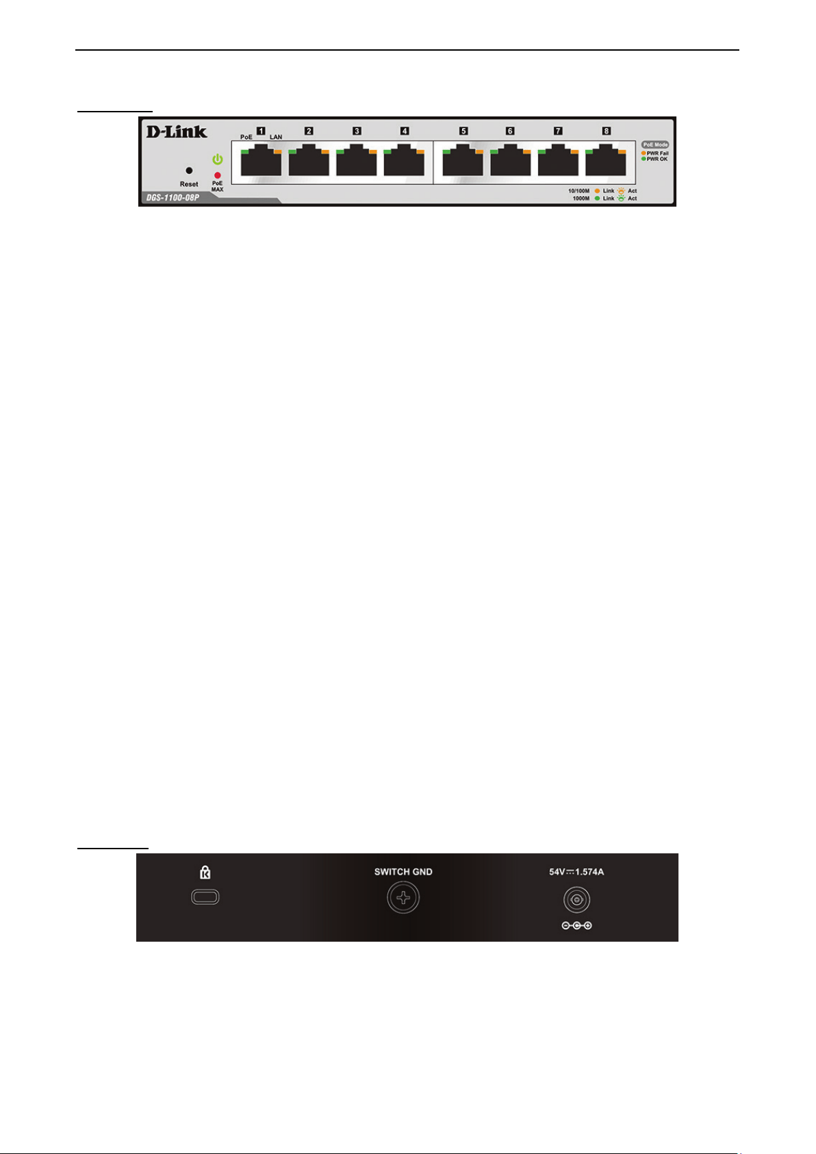
Figure 1.8 – DGS-1100-08P Rear Panel
Power: Input for a 54V/1.574A AC adapter.
Kensington Lock: This is used to attach a physical Kensington security lock.
GND: This is used to connect the Switch to ground.
Loading ...
Loading ...
Loading ...