
Loading ...
Loading ...
Loading ...
W415-1087 / A / 06.06.13
14
EN
4.3 FACTORY BUILT FIREPLACE
The following installation requirements must be observed when installing solid fuel burning inserts into factory
built fi replaces.
A. The factory built fi replace must be listed per UL 127 or ULC S610.
B. Clearances to any combustible material surrounding this insert as identifi ed must be followed. These
clearance requirements supersede any pre-existing facing material clearances listed for the factory
built fi replace.
C. Installation must include a full height listed chimney liner meeting HT requirements (2100°F/1149°C)
as required in UL 1777 (U.S.) or ULC S635 (Canada). The liner must be securely attached to the insert
fl ue collar and the chimney top.
D. Means must be provided to prevent room air passage to the chimney cavity of the fi replace. This may
be accomplished by sealing the damper area around the chimney liner, or sealing the appliance front.
E. The air fl ow within and around the appliance shall not be altered by the installation of the insert (i.e.
no louvres or cooling air inlet or outlet ports are blocked), unless specifi cally tested as such for each
factory built fi replace manufacturer and model line. NOTE: Using a louvered face plate (surround)
complies with this requirement.
F. Alteration of the appliance in any manner is not permitted with the following exceptions;
A. External trim pieces which do not affect the operation of the appliance may be removed providing
they can be stored on or within the fi replace for reassembly if the insert is removed.
B. The chimney damper may be removed to install the chimney liner.
G. Circulating air chambers (i.e. in a steel fi replace liner or metal heat circulator) shall not be blocked.
H. Means must be provided for removal of the insert to clean the chimney fl ue.
I. Inserts that project in front of the fi replace must be supplied with appropriate support means.
J. A permanent metal warning label must be attached to the back of the fi replace stating that the fi replace
must be restored to its original condition for safe use without the insert.
80.2B
5.0 FINISHING
5.1 SECONDARY AIR TUBES
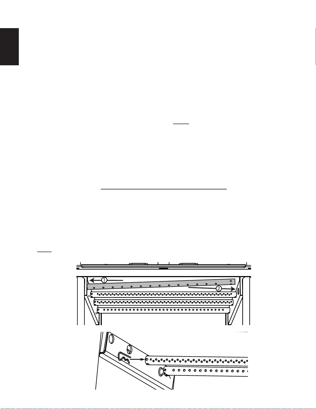
A. Starting at the back with the shortest tube and working forward, install the secondary air tubes by fi rst
inserting the tube into the hole on the left side of the fi rebox and then into the corresponding hole on
the right side, align the notch with tab, slide the tube all the way to the right, refer to Figure 1.
B. Insert the cotter pin to secure the tube in place, refer to Figure 2.
NOTE: We recommend leaving the front tube out until the fi bre baffl e has been installed.
Figure 1
Figure 2
Loading ...
Loading ...
Loading ...