Loading ...
Loading ...
Loading ...
9
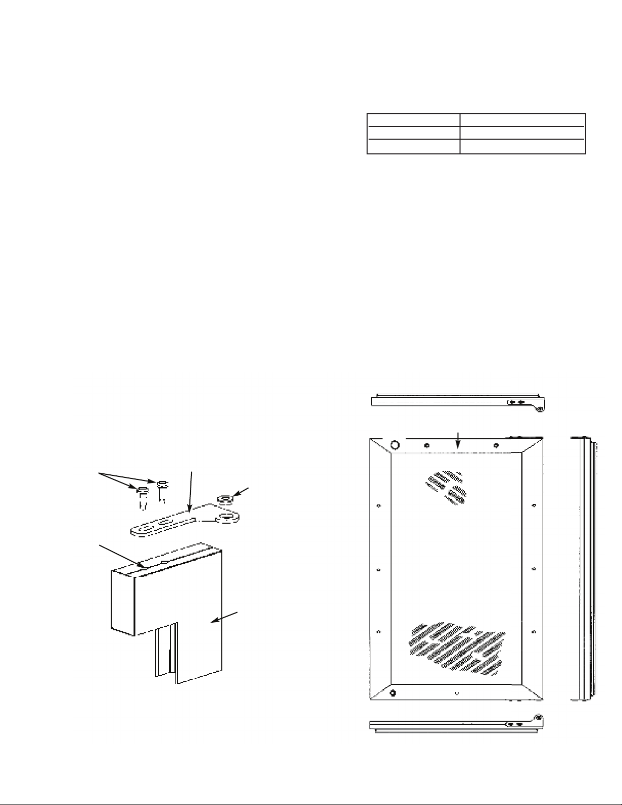
FIGURE 1 FIGURE 2
Typical Top and Bottom Door
Hinge Bracket Assembly
Door Front
Surface
Shoulder Bushing
Door
Hinge
Bracket
#10-32
Machine
Screw
Door Hinge
Screw Holes
This surface parallel to the unit.
(Right hinge door shown.)
CUSTOM WOOD FRAME INSTALLATION (DFUW Model)
NOTE: Weight of wood panel must not exceed 20 lbs.
W
ood Screws
1
. A #10 pan head wood screw should be used to properly secure the wood panel. A total of 8 screws will be needed.
2. Only use pan head screws.
3. DO NOT select a screw that is longer than the wood thickness at
the screw locations.
4. Use recommended pilot holes for the frame material. (See chart)
Working Material Wood Screw Size #10
Hardwood 3/32 (0.24 cm)
S
oftwood 5/64 (0.20 cm)
Assembling Door Hinge Brackets
(Disregard if hinge brackets are already attached)
1. Attach the top and bottom door hinge brackets to the door with the #10-32 machine screws and a 1/8” allen head
driver as shown in Figure 1 below.
2. Press in the shoulder bushings to the top and bottom door hinge brackets. Make certain that the shoulder is to the
outside of the door as shown in Figure 1 below.
3. Test fit the door to the unit to make certain door will hang correctly. The door is hung correctly when the top of the
door is parallel to the top of the unit. Adjustments can be made by loosening the door hinge machine screws and
moving the door hinge brackets on the door.
4. Tighten all four (4) machine screws after adjustments have been made.
5. Remove the door from the unit by removing the units top hinge set screw and angling the door off of the bottom
hinge pin.
Loading ...
Loading ...
Loading ...