Loading ...
Loading ...
Loading ...
16
ASSEMBLY
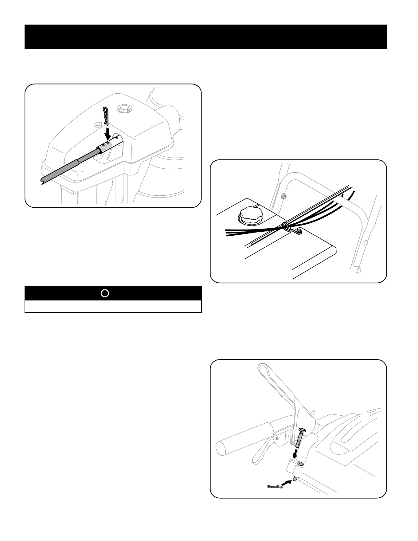
6. Push the chute control rod toward the control panel until the hole in the rod
lines up with the middle hole in the chute control input and insert the cotter
pin removed in Step 1. See Figure 32.
Figure 32
NOTE: There is a reference hole provided at rear end of control rod to help
know when holes are vertical.
NOTE: The hole furthest from the chute control head is used to achieve
further engagement of the chute control rod into the input shaft if required.
Refer to Page 31 of the Maintenance & Adjustments section for Chute Control
Rod adjustment.
STOP
Continue to Set-Up (page 16).
Set-Up
Chute Control Cable Routing (If Equipped)
For units equipped with 2-way or 4-way chute control joystick, electric chute
control and/or chute-pitch controls, ensure control cables are routed properly.
NOTE: For smoothest operation, cables should all be to the left of the chute
directional control rod.
NOTE: The number of cables routed through the wire guides will depend on unit
model.
1. Locate cable guide on top of engine and ensure cable(s) are properly routed
through the cable guide. See Figure 33.
Figure 33
Shear Pins
Holes are located in the plastic dash panel for convenient shear pin storage. See
Figure 34. Refer to page 27 in the Operation section for more information
regarding shear pin replacement.
NOTE: If the extra shear pins are not already assembled in the handle panel, they
can be found in the manual bag.
Figure 34
Loading ...
Loading ...
Loading ...