Loading ...
Loading ...
Loading ...
Installation procedure en-us
13
WARNING
ELECTRICAL GROUNDING INSTRUCTIONS
▶ This appliance (HIS8..5C) is equipped with a four-prong
grounding plug for your protection against shock hazard
and should be plugged directly into a properly grounded
receptacle. Do not cut or remove the grounding prong
from this plug.
3.7 Preparation for power connection
WARNING
Risk of Electric Shock or Fire. Grounding through the neu-
tral conductor is prohibited for new branch-circuit installa-
tions (1996 NEC), mobile homes, and recreational vehi-
cles, or in an area where local codes prohibit grounding
through the neutral conductor.
For installations where grounding through the neutral con-
ductor is prohibited: (a) disconnect the link from the neu-
tral, (b) use grounding terminal or lead to ground unit, (c)
connect neutral terminal to lead branch circuit neutral in
the usual manner. When the appliance is to be connected
by means of a cord kit, use 4-conductor cord for this pur-
pose.
Use only cord kits rated 208/240volts, 50amperes, with
ring or fork type connector and labelled "For use with
ranges”. Use only flexible conduit with wires with ring or
fork type connectors. Strain relief provided with the cord
must be installed per instructions included with the cord.
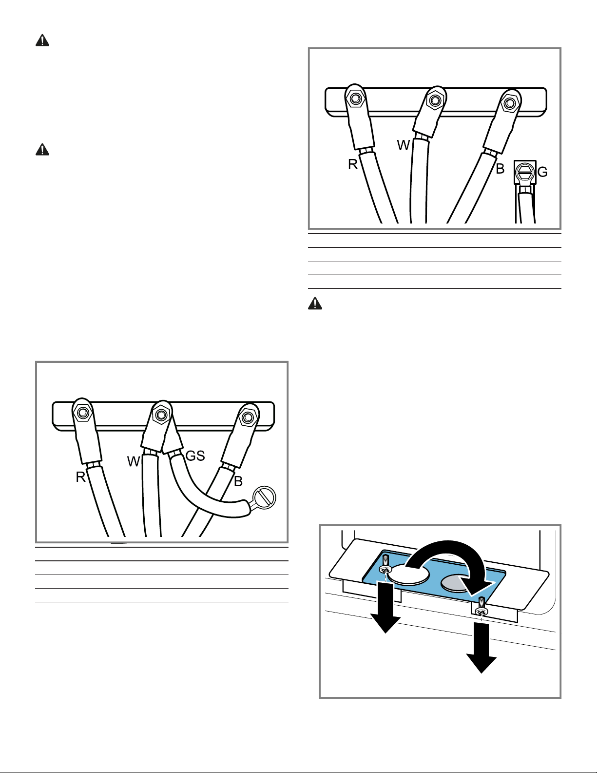
3-Wire Hookup
R Red
W White
GS Grounding Strip
B Black
4-Wire Hookup
R Red
W White
G Green
B Black
WARNING
To prevent electrical shock, the grounding prong on the
range cord should not be cut or removed under any cir-
cumstances.
▶ It must be plugged into a matching grounding type re-
ceptacle and connected to a correctly polarized 240-
Volt circuit.
▶ If there is any doubt as to whether the wall receptacle is
properly grounded, have it checked by a qualified elec-
trician.
3.8 Four-wire range cord connection (recom-
mended method)
1. Disconnect the electrical power at the breaker box. Re-
move the terminal block cover to expose the terminal
block.
2. If you need a lager hole for the strain relief (not provided
with range) remove the metal plate. Rotate it 180° to
have the lager hole for the power supply cable and
mount it again.
3. Insert the power supply cable into the terminal block
through the bottom hole.
Loading ...
Loading ...
Loading ...