N841_QSG_EN_R3
Test your cameras prior to selecting a permanent mounting location by temporarily
connecting the cameras and cables to your NVR using one of the following 2 methods:
a. Connect cameras directly to the recorder (recommended).
N841 Series
Quick Setup Guide
Physical setup of recorder and essential system settings
b. Connect cameras to a PoE switch or router on your network (not included).
1 / 2
Connect the recorder to your router using the included Ethernet cable.
NOTES:
• It may take up to 1 minute for cameras to start up and transmit video to your recorder.
• This guide covers connecting IP cameras to your security recorder only. For full instructions on
installing your cameras, please refer to your camera’s documentation at lorex.com.
• Connecting cameras to a router, or a network switch without PoE, requires a power adapter for
each camera. Refer to your camera’s documentation at lorex.com for the correct power adapter
model number.
OR
NOTES:
• If you are using a PoE switch, ensure the switch is connected to the same network as your
recorder.
• To receive automatic rmware updates and enable remote viewing with mobile apps, a high
speed Internet connection is required (minimum upload speed of 5Mbps required for 4K viewing;
3.5Mbps for lower resolutions). All other system features can be used without an Internet
connection.
Copyright © 2020 Lorex Corporation
As our products are subject to continuous improvement, Lorex reserves the right to modify product design, specications
and prices, without notice and without incurring any obligation. E&OE. All rights reserved.
Need Help?
Visit us online for up-to-date software
and complete instruction manuals
Click on the Downloads tab
4
Visit lorex.com
Search for the model
number of your product
Click on your product
in the search results
3
2
1
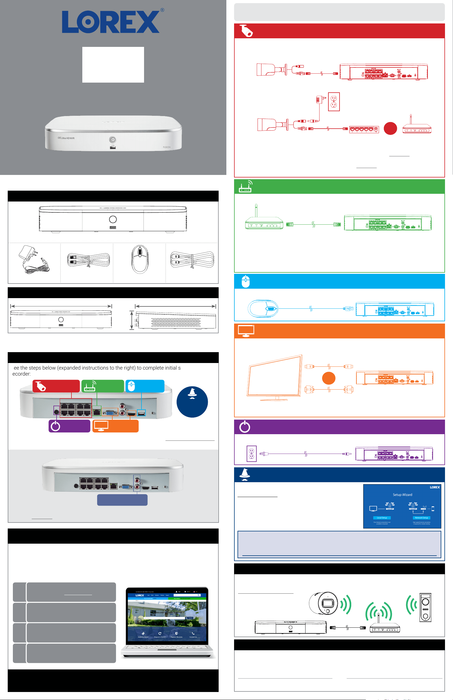
See the steps below (expanded instructions to the right) to complete initial setup of the
recorder:
Lorex Fusion supports connectivity with select wireless devices to the NVR. To learn more
about fusion connectivity and which Lorex devices are compatible with this feature, visit
lorex.com/pages/fusion.
* Not included / sold separately.
For camera compatibility information, visit lorex.com/compatibility.
STEP 1:
Connect cameras*
STEP 2:
Connect router*
STEP 3:
Connect mouse
STEP 5:
Connect power
STEP 4:
Connect monitor*
Overview of extra ports:
NOTE: For full instructions on using the extra ports, please refer to your security recorder’s instruction
manual at lorex.com.
Audio In/Out
Connect microphone / speaker*
Setting Up Your Recorder
USB MouseEthernet CablePower Adapter HDMI Cable
4K Ultra HD Security NVR
12.8” / 324mm
9.8” / 249mm
2.4”
60mm
Package Contents
Dimensions
Lorex Fusion
s
STEP 1: Connect cameras*
Connect the recorder to a monitor using the included HDMI cable or a VGA cable (not
included). The HDMI port supports up to 4K resolution, and VGA supports up to 1080p.
Connect the included mouse to a USB port on the recorder.
Use the included power adapter to connect the recorder to a nearby outlet.
OR
IMPORTANT: To optimize picture quality, set the recorder’s video output to match the resolution of your
monitor. See the section Changing the Recorder’s Output Resolution on the rear for details.
Back panels shown below are for illustration only. Your recorder’s back panel
may appear different, with all the same ports in different locations.
STEP 2: Connect router*
STEP 3: Connect mouse
STEP 4: Connect monitor*
STEP 5: Connect power
To quickly open a window that displays vital system information such as device ID, model
number, rmware version, and IP address:
Reference: Quick Access to System Information
• Tap the button on the front panel of the recorder.
• Right-click to open the Quick Menu and click Info.
OR
STEP 6:
Lorex Setup
Wizard
Record your password below and store in a secure place:
When you rst power up your recorder, the
Lorex Setup Wizard will begin. The Wizard will help you
congure core system settings.
You will also create a secure password. For future reference,
it is recommended that you record your password here:
STEP 6: Lorex Setup Wizard
N841_QSG_EN_R3
Adding Cameras from the LAN
Follow the steps below to add cameras that are not directly connected to the Power over
Ethernet (PoE) ports on the back of the recorder.
NOTE: Please visit lorex.com/compatibility for a list of compatible Lorex IP cameras.
To add cameras from the LAN:
1. Connect the camera to a router or switch on the same network as the recorder.
2. Right-click and select Device Search. If prompted, log in using the system user name (default:
admin) and your new, secure password.
3. Congure the following:
a. Click Device Search.
b. Check the camera(s) you would like to
add.
c. Click Add. The status indicator
turns green to show the camera is
successfully connected.
d. The added device(s) will appear in the
Added Device list. Right-click to exit to
live view.
NOTE: If the icon in the Status column
appears red, there may be a password
issue with the camera. Select the
camera and click Reconnect IPC.
Search through and play video recordings from the hard drive.
To search for and play recordings:
1. From live view, right-click and then click Playback. If prompted, log in using the system user name
(default: admin) and your new, secure password.
2. Congure the following:
Playback and Search
a. Use the calendar on the right to
select the date to playback.
b. Check channels you want to play
back. Click the grey icon beside
each selected channel to select
Mainstream (M) or Substream
(S) video quality.
c. Click inside the video bar
to select the playback time.
Playback starts immediately at
the selected time.
b
a
c
Back up recordings from the hard drive to a USB ash drive (not included).
To back up recordings:
1. Insert a USB ash drive (not included) into a free USB port on the recorder.
2. From live view, right-click and then click Main Menu. If prompted, log in using the system user
name (default: admin) and your new, secure password.
3. Click
, then click BACKUP.
4. Congure the following:
Backup
a. Select the type and quality of
recordings to search for.
b. Select the channel(s) to search
by.
c. Select a Start Time and End
Time for your search.
d. Choose a le format for your
backed up les.
e. Click Add to see recordings that
match your search.
f. Check boxes next to recordings
you want to back up, then
click Start. You may also click
Onekey Backup to back up all
les that match your search.
a
b
c
d
e
f
Once you have completed all steps for initial setup on the front of this guide, please refer
to the following sections to learn more about using your system.
1. In live view, right-click and click Main Menu. If prompted, log in using the system user name
(default: admin) and your new, secure password.
2. Click
, then select EVENT. Select the Deterrence tab.
3. Congure the following:
To congure advanced person/vehicle detection or active deterrence:
Congure advanced motion detection and/or active deterrence settings. For a complete list
of compatible cameras, navigate to your recorder series at lorex.com/compatibility.
a. Select the channel of
a connected camera
with person and vehicle
detection.
b. Check Enable
underneath Person and/
or Vehicle.
a
b
c
f
c. Click Set next to Area to set active areas for person and/or
vehicle detection. See Figure 1 below for details.
d. Click Set next to Schedule to set a weekly schedule for person
and/or vehicle detection. See Figure 2 below for details.
e. Set preferences for the warning light and siren.
f. Click OK.
To set off all connected deterrence cameras’ warning lights and
sirens, press and hold the front panel button for 3 seconds.
Advanced Motion Detection & Deterrence Settings
d
e
Figure 2: Schedule
Figure 1: Detection Area
• Click Add to set an area for person or vehicle detection
on the selected channel. Click-and-drag the corners to
resize the area.
• For most accurate results, set an area where objects of
interest will move within the bounding box as well as
into / out of.
• Check Light next to a rule to ash the camera’s
warning light when an object is detected.
• See your camera’s documentation for optimal camera
positioning for person and vehicle detection.
Option 1: Advanced Person/Vehicle Detection Cameras
Option 2: Active Deterrence Cameras
• The default schedule, shown in Figure 2, is active during
the night, between 5pm and 7am.
• Click Set to change the schedule for the corresponding day
of the week.
• Click OK when nished.
a
b
c
g
d
e
f
a. Select the channel of a
connected deterrence camera.
b. Check Enable.
c. Click Set next to Area to set
active areas for person and/or
vehicle detection. See Figure 3
below for details.
d. Click Set next to Schedule to set a weekly schedule for
person and/or vehicle detection. See Figure 2 above for
details.
e. Set preferences for the warning light and siren.
f. Set Sensitivity and Threshold levels to your preference.
g. Click OK.
• The camera image appears with a grid overlay. The
green area is the active area for deterrence.
• Click or click-and-drag to add / remove boxes from the
active area.
• In Figure 3, only motion around the doorway will trigger
the warning light.
• Right-click when nished.
Figure 3: Deterrence Area
a
b
c
Changing the Recorder’s Output Resolution
To ensure the best possible picture quality, set the recorder’s output resolution to match the
highest resolution supported by your monitor.
a. Set Resolution to match the
highest resolution supported
by your monitor. For example,
select 3840×2160 for 4K
monitors, or 1920×1080 for
1080p.
b. Click OK. The recorder will
restart before changes take
effect.
a
b
To change the recorder’s output resolution:
1. From live view, right-c lick and then click Main Menu. If prompted, log in using the system user
name (default: admin) and your new, secure password.
2. Click Display, then congure the following:
IMPORTANT: If you need to switch the monitor, make sure you set the recorder to an output resolution
supported by the new monitor before switching.
Using the Mouse
NOTE: In live view, hover the mouse cursor over the top of the screen to open the Navigation Bar. Move
the mouse cursor away from the top of the screen to close the Navigation Bar.
During live view: Use the scroll wheel to zoom in / out.
• During live view: Click
anywhere on the screen to
open the Quick Menu.
• While navigating menus:
Click to exit menus.
• During split-screen display
mode: Click an individual
channel to view in full-screen.
Click again to return to the
split-screen display mode.
• While navigating menus:
Click to open a menu option.
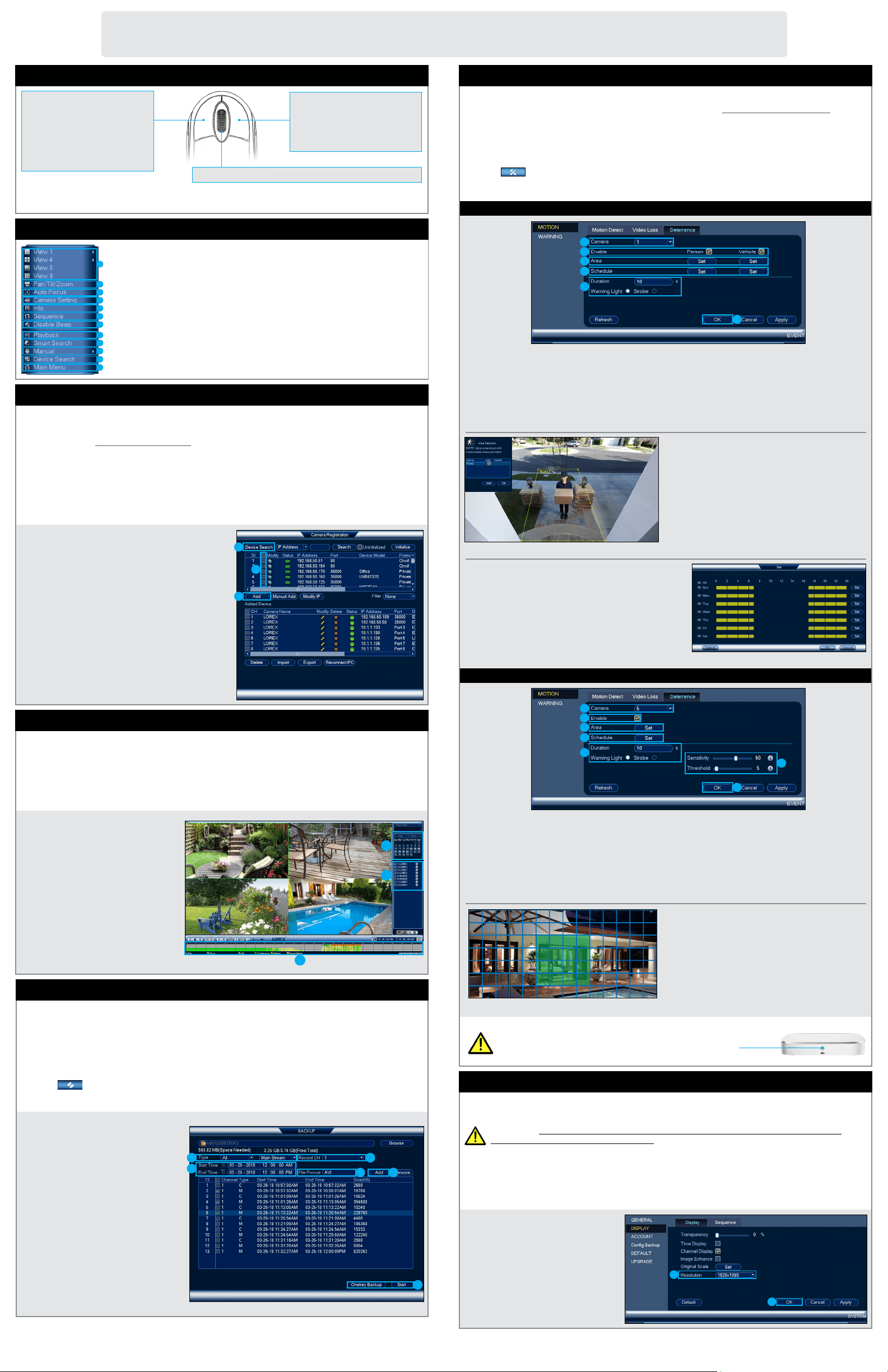
Using the Quick Menu
Right-click anywhere on the live viewing screen to open the Quick Menu.
b
a
c
d
e
f
g
h
i
j
k
a. Select camera/live display view.
b. Control PTZ cameras (not included).
c. Control auto focus cameras (not
included).
d. Adjust camera color and image
settings.
e. View system information.
f. Start/stop sequence mode.
l
g. Temporarily disable all current
audible warnings.
h. Search and play back recordings.
i. Search for and play back person /
vehicle detection events.
j. Open manual recording controls.
k. Add IP cameras over the LAN.
l. Open Main Menu.
4K Ultra HD Active
Deterrence Security Camera
Quick Start Guide
www.lorex.com
English Version 1.0
E891AB Series
E891AB_QSG_EN_R1
• 4K Ultra HD Bullet IP Camera
• Mounting Kit*
• Ethernet Extension Cable with Pre-attached RJ45 Cable Gland*
* Per camera in multi-camera packs.
Package Contents
ATTENTION:
It is recommended to connect the camera to the NVR or an external PoE switch. If using a DC power
adapter (not included) with the camera, a REGULATED power supply is REQUIRED for use with this
camera. Use of a non-regulated, non-conforming power supply can damage this product and voids the
warranty.
• Use the camera only with compatible Lorex NVRs.
• Read this guide carefully and keep it for future reference.
• Follow all instructions for safe use of the product and handle with care.
• Use the camera within given temperature, humidity and voltage levels noted in the camera’s
specifications.
• Do not disassemble the camera.
• Do not point the camera directly towards the sun or a source of intense light.
• Use only a regulated power supply with the product (optional). Use of a non-regulated, non-
conforming power supply can damage the product and void the warranty.
• Periodic cleaning may be required. Use a damp cloth only. Do not use any harsh, chemical-based
cleaners.
• Check the packaging of the included cable to verify cable grade based on model number.
CBL605U: The supplied cable is rated for surface and in-wall mounting. CBL100C5: The supplied
cable is rated for surface mounting only. Cables for in-wall and floor-to-floor installations are
sold separately (CMR type). These and other cables are available at lorex.com.
Safety Precautions
Need Help?
Visit us online for up-to-date software
and complete instruction manuals
Click on the Downloads tab
4
Visit lorex.com
Search for the model
number of your product
Click on your product
in the search results
3
2
1
Copyright © 2019 Lorex Corporation
As our products are subject to continuous improvement, Lorex reserves the right to modify product
design, specifications and prices, without notice and without incurring any obligation. E&OE. All rights
reserved.
Dimensions
7.3” / 187mm3.0” / 75mm
• For a full list of compatible recorders, visit lorex.com/compatibility.
• To ensure that you are viewing camera video in full 4K resolution (4K monitor required),
check the video output resolution of your recorder. For full instructions, see your recorder’s
documentation at lorex.com.
• Not intended for submersion in water. Installation in a sheltered location recommended.
• This camera includes an Auto Mechanical IR Cut Filter. When the camera changes between Day/
Night viewing modes, an audible clicking noise may be heard from the camera. This clicking is
normal, and indicates that the camera filter is working.
Disclaimers
ATTENTION:
• Test your camera prior to selecting a permanent mounting location by temporarily connecting
the camera and cable to your NVR.
• Review the section “STEP 1: Important Installation Guidelines” above before choosing a
permanent mounting location.
Before Installing the Camera
• Decide whether to run the cables through
the wall / ceiling (drilling required) or
along the wall / ceiling.
• If you run the cables along the wall /
ceiling, you must run the cable through
the cable notch on the base. This will
keep the camera base flush to the
surface when mounted.
Cable Notch
To install your camera:
1. Use the included mounting template to mark holes for the screws. Drill
holes for the mounting screws.
NOTE: Insert the included drywall anchors if you are installing the camera
in drywall.
2. Connect cables as shown in the section “Connecting the Camera”.
3. Feed the cable through the mounting surface or cable notch and mount
the camera stand to the surface using the provided screws.
4. Use a Philips head screwdriver (not included) to loosen the adjustment
screws shown below. Adjust the camera position as needed:
A. Rotate the camera
base 360°.
B. Tilt the camera on
the stand up to 90°.
C. Twist the camera
around the stand 360°.
A B C
5. Tighten the adjustment screws to secure the position.
6. Remove the vinyl film from the camera lens when your installation is
complete.
Additional Installation Tips:
• Point the camera where there is the least amount of obstructions (e.g., tree branches).
• Install the camera where vandals cannot easily reach.
• Secure cabling so that it is not exposed or easily cut.
• This camera is rated for outdoor use. Installation in a sheltered location is recommended.
STEP 1: Important Installation Guidelines
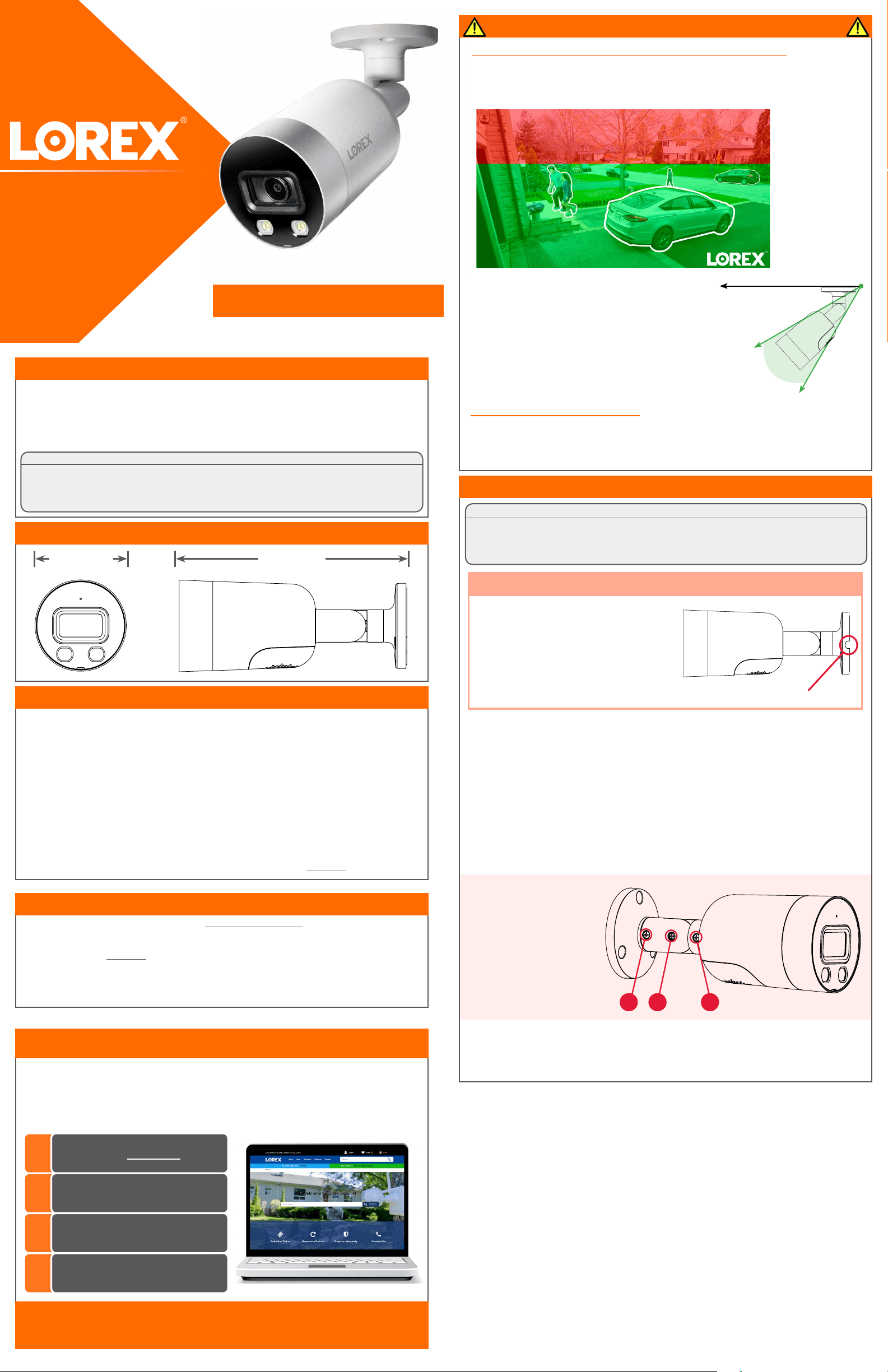
Optimizing Person and Vehicle Detection Accuracy:
• Angle the camera so that objects of interest appear in the bottom ⅔ of the camera
image.
• Choose a location where objects of interest will be no further than 50ft (~15m) from
the camera.
Optimal accuracy
for objects within
50ft (~15m) and in
the bottom ⅔ of the
image.
Lower accuracy for
objects further away
than 50ft (~15m) and/
or in the top ⅓ of the
image.
• Angle the camera between 30~60° down from the
level position.
• Install the camera between 8-16ft (2.5-5m) off of
the ground.
STEP 2: Installing the Camera
Level position (i.e., ceiling)
Optimal
angle
range
NOTE: Accuracy of person and vehicle detection will
be influenced by multiple factors, such as the object’s
distance from the camera, the size of the object, and
the height and angle of the camera. Night vision will
also impact the accuracy of detection.
Connecting the Cameras
Setup Diagram
CameraNVR
Scenario 1: Connect Cameras to NVR
Scenario 2: Connect Cameras to Local Area Network (LAN)
Router
Camera
NVR
Router
PoE Switch
ATTENTION:
• This camera is only compatible with select NVRs. For a list of compatible
recorders, visit lorex.com/compatibility.
• You must connect the camera to a supporting H.265 NVR to take advantage
of H.265 compression. For instructions on enabling H.265 compression, visit
lorex.com, and search for “How do I enable H.265 compression?”.
E891AB_QSG_EN_R1
Problem Solution
No picture / signal • Ensure the camera is connected to a compatible NVR. For full
compatibility, visit lorex.com/compatibility.
• The camera may take up to 1 minute to power up after being
connected to the NVR. Wait two minutes before following the steps
below.
• Ensure the camera is connected to your NVR or to your local
network.
• If you are not using PoE, you must connect the camera to a 12V DC
power adapter (not included).
• If the camera is connected to the LAN, you must search your
network for cameras using the NVR. See the NVR’s instruction
manual.
• Ensure your NVR is properly connected to a monitor.
• There may be an issue with your extension cable run. Connect the
camera to the NVR using a different Ethernet cable.
Picture does not
appear to be 4K
• To ensure that you are viewing camera video in full 4K resolution
(4K monitor required), check the video output resolution of your
NVR. For full instructions, see your NVR’s documentation at
• lorex.com.
Picture is too bright • Ensure your camera isn’t pointed directly at a source of light (e.g.,
sun or spot light).
• Move your camera to a different location.
• Check the brightness and contrast settings on the NVR.
Picture is too dark • Check the brightness and contrast settings on the NVR.
Night vision is not
working
• The night vision activates when light levels drop. The area may
have too much light.
Picture is not clear • Check the camera lens for dirt, dust, spiderwebs. Clean the lens
with a soft, clean cloth.
• Make sure that the cable run is within the limitations specified in
the section ‘Cable Extension Options’.
• Remove the vinyl film from the camera lens when your installation
is complete.
Bright spot in video
when viewing camera
at night
• Night vision reflects when pointing a camera through a window.
Move the camera to a different location.
Picture is in color in
dark conditions
• This camera's image sensor is extra sensitive to light, meaning
that the camera stays in color mode at low-light conditions. For
instructions on how to make your camera switch to night mode,
visit lorex.com, and search for “How do I make my camera switch
to night mode?”.
The camera warning
light is not switching on
automatically
• Ensure that you have enabled and configured white light
deterrence using a compatible NVR. See your NVR’s
documentation for full instructions.
• Ensure the active areas and schedule for white light deterrence
are set properly. The default schedule for the warning light is night
times (between 5PM and 7AM).
The camera siren
is not switching on
automatically
• The camera siren cannot switch on automatically. You can control
the camera siren manually using a compatible Lorex NVR or app.
Refer to your NVR’s documentation for full instructions.
No audio
• Audio is only supported on Lorex NVRs. For a list of compatible
recorders, visit lorex.com/compatibility.
• Ensure NVR volume is turned on / turned up.
• Ensure audio function on camera is turned on (see ‘Audio
Settings’).
• Ensure audio is turned up on viewing device.
Two-way talk not
working
• Use the Lorex app specified in your NVR documentation to activate
two-way talk. Tap
from the camera's live view, then speak into
the microphone on your mobile device. Tap again when finished
speaking.
Troubleshooting
Connect the Ethernet cable to the
camera.
Connect the other end of the Ethernet
cable to the NVR’s PoE ports. The
camera may take a minute to power up
after being connected.
Connecting the Camera
Connect the other end of the Ethernet
cable to a router or switch on your
network. See your NVR manual for
details on connecting the camera to
your NVR using a switch or router.
Camera
NVR
OR
(Optional)
12V DC Power
Ethernet Cable
NOTE: A 12V DC power adapter
(model#: ACCPWR12V1, not included)
is only required if connecting the
camera’s Ethernet cable to a router
or switch that does not support PoE.
• You can use a RJ45 coupler or network switch (not included) to connect male ends of
Ethernet cable together.
• To extend the cable run beyond 300ft (91m), a switch will be required (sold separately).
Extend the Ethernet cable run for your camera up to 300ft (91m). See table below. It is
recommended to use UL CMR approved cables available at lorex.com.
Cable Extension Options
Cable Type
Max Cable Run
Distance
Max # of
Extensions
CAT5e (or higher) Ethernet cable 300ft (91m) 3
Using the RJ45 Cable Gland (Optional)
The pre-attached RJ45 cable gland covers the camera’s Ethernet connector and the
RJ45 plug to provide weather-resistance and protection from dust, dirt and other
environmental contaminants.
To use the RJ45 cable gland:
RJ45 Cable
Gland Barrel
Camera Ethernet
Connector
NOTE: The RJ45 cable gland is weather-resistant. Seal the cap with silicone and/or electrical tape
for additional sealing if it will be exposed to precipitation regularly.
Twist the RJ45 cable gland barrel
securely onto the camera Ethernet
connector.
A
B
Using Deterrence Features
Use your Lorex app to manually activate the camera's white light and siren features
when connected to a compatible Lorex recorder.
PREREQUISITE: Connect to your Lorex system using the app specified in your recorder
documentation.
To activate deterrence features manually:
1. Launch the app and tap your recorder to view connected channels.
2. Tap a connected deterrence camera to open it in single-channel view.
3. Tap
to activate the white light, or tap to activate the siren.
NOTE: You can also set schedules and active areas of the camera image where the white light will
be triggered automatically when motion is detected. For full instructions, refer to the app manual
on your product page at lorex.com.
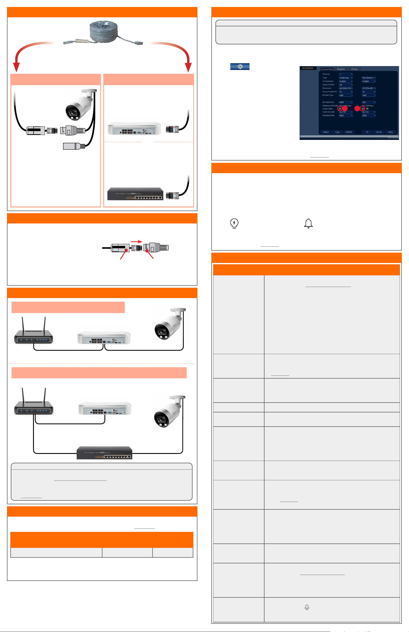
Audio Settings
NOTE: These instructions are based on current NVR interface. For the most up-to-date
instructions, see your NVR’s instruction manual on lorex.com.
To enable audio recording and listen-in audio:
1. From Live View, right-click and click Main Menu. Enter the system user name (default: admin)
and password.
2. Click
and select Recording.
ATTENTION:
Audio recording and listen-in audio are disabled by default. Audio recording and/or use of listen-in
audio without consent is illegal in certain jurisdictions. Lorex Corporation assumes no liability for use
of its products that does not conform with local laws.
3. Under Channel, select the channel
where the audio-capable camera is
connected.
4. Under Audio/Video:
A. Check to enable audio recording and
listen-in audio.
NOTE: Listen-in audio requires a
monitor with speakers or speakers
connected to the NVR.
B. (Optional) Check to enable audio
streaming to mobile applications.
5. Under Audio Encode, select the format
that will be used to record audio. G711A
is recommended.
6. Click OK to save changes.
