HeartRateControl
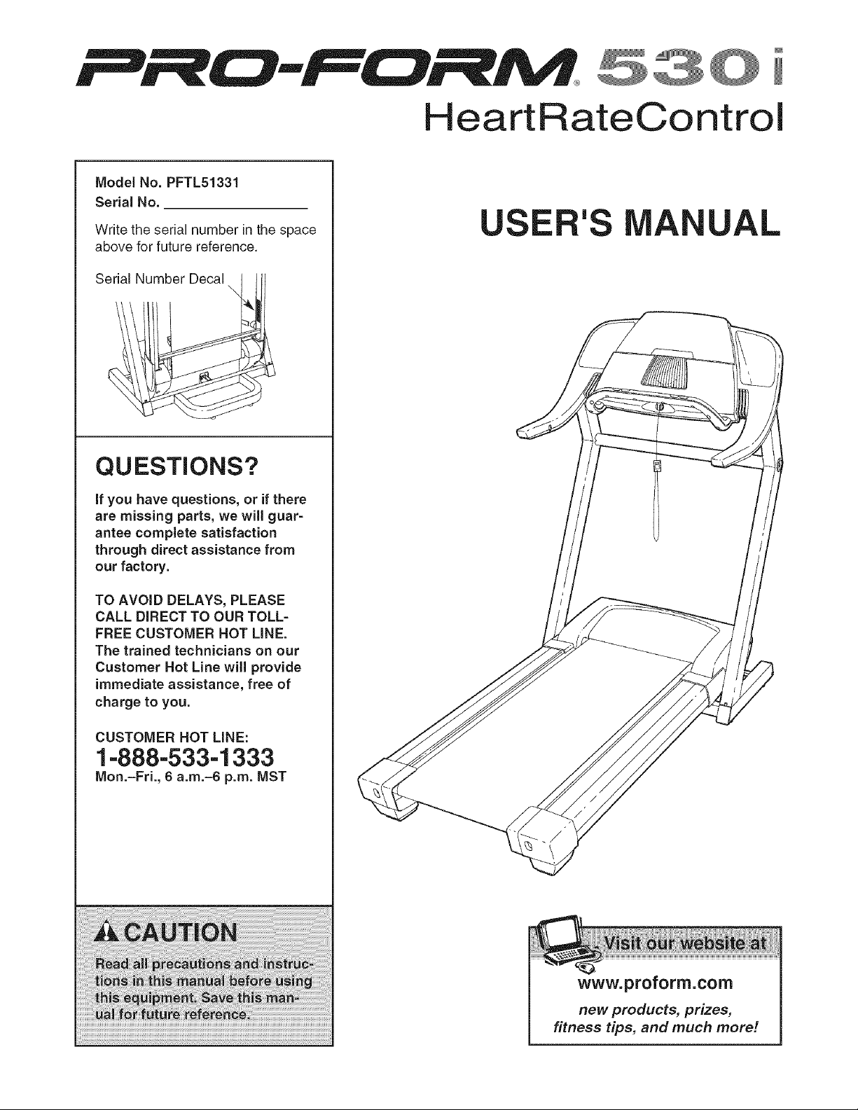
Model No. PFTL51331
Serial No.
Write the serial number in the space
above for future reference.
Serial Number Decal
\
QUESTIONS?
if you have questions, or if there
are missing parts, we will guar=
antee complete satisfaction
through direct assistance from
our factory.
TO AVOID DELAYS, PLEASE
CALL DIRECT TO OUR TOLL=
FREE CUSTOMER HOT LINE.
The trained technicians on our
Customer Hot Line will provide
immediate assistance, free of
charge to you.
CUSTOMER HOT LINE:
1-888-533-1333
Mon.-Fri., 6 a.m.-6 p.m. MST
USE 'S
AL
www.proform.com
new products, prizes,
fitness tips, and much more!

HeartRateControl
TABLE OF CONTENTS
IMPORTANT PRECAUTIONS ................................................................. 3
BEFORE YOU BEGIN ....................................................................... 5
ASSEMBLY ............................................................................... 6
TREADMILL OPERATION ................................................................... 10
HOW TO FOLD AND MOVE THE TREADMILL .................................................. 24
TROUBLESHOOTING ...................................................................... 26
EXERCISE GUIDEMNES ................................................................... 28
PART MST ............................................................................... 30
HOW TO ORDER REPLACEMENT PARTS .............................................. Back Cover
LIMITED WARRANTY ............................................................... Back Cover
Note: An EXPLODED DRAWING is attached in the center of this manual.
PROFORM is a registered trademark of ICON IP, Inc.
2

iMPORTANT PRECAUTIONS
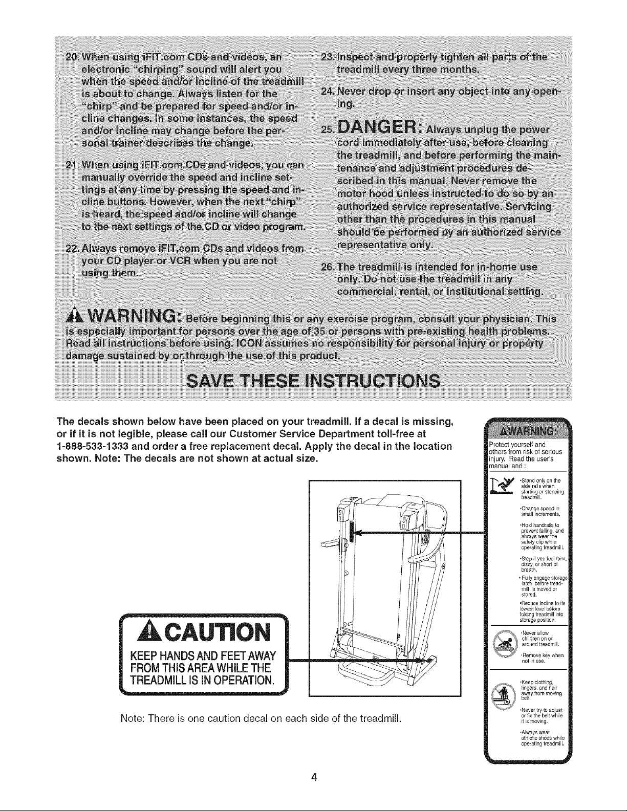
The decals shown below have been placed on your treadmill. If a decal is missing,
or if it is not legible, please call our Customer Service Department toll=free at
1=888=533=1333 and order a free replacement decal. Apply the decal in the location
shown. Note: The decals are not shown at actual size.
CAUT|ON
KEEP HANDSAND FEET AWAY
FROM THISAREA WHILE THE
TREADMILLiS iN OPERATION.
Note: There is one caution decal on each side of the treadmill.
4
Protect yourself and
others from risk of serious
injury. Read the user's
manual and :
_, "Stand onlyon the
side rails when
starting or stopping
treadmill.
.Changespeed h_
small _ncrements.
• Hold handrails to
prevent falling, and
always wear the
safety clip while
operating treadmill,
.Stop if you feel faint,
dizzy, or short of
breath.
• Fully engage storag_
latch before tread-
mill is moved or
stored.
,Reduce incline to its
lowest level before
folding treadmill into
sto_age posLbon,
not]n use,
,Keep clothing,
fingers, and hair
away from moving
belt.
.Never try to adiust
or fix the belt while
it is moving.
.Always wear
athletic shoes while
operating treadmill.
BEFORE YOU BEGIN
Congratulations for purchasing the PROFORM _>530i
treadmill. The 530i treadmill offers an impressive array
of features to help you achieve your fitness goals in
the convenience of your home. From the advanced
console to the cushioned walking platform, the 530i
treadmill is designed to make each workout more ef-
fective and enjoyable. And when you're not exercising,
the treadmill can be folded away, taking less than half
the floor space of conventional treadmills.
For your benefit, read this manual carefully before
using the treadmill, if you have questions after read-
ing this manual, call our Customer Service Department
toll-free at 1-888-533-1333, Monday through Friday, 6
a.m. until 6 p.m. Mountain Time (excluding holidays).
To help us assist you, please note the product model
number and serial number before calling. The model
number is PFTL51331. The serial number can be
found on a decal attached to the treadmill (see the
front cover of this manual for the location).
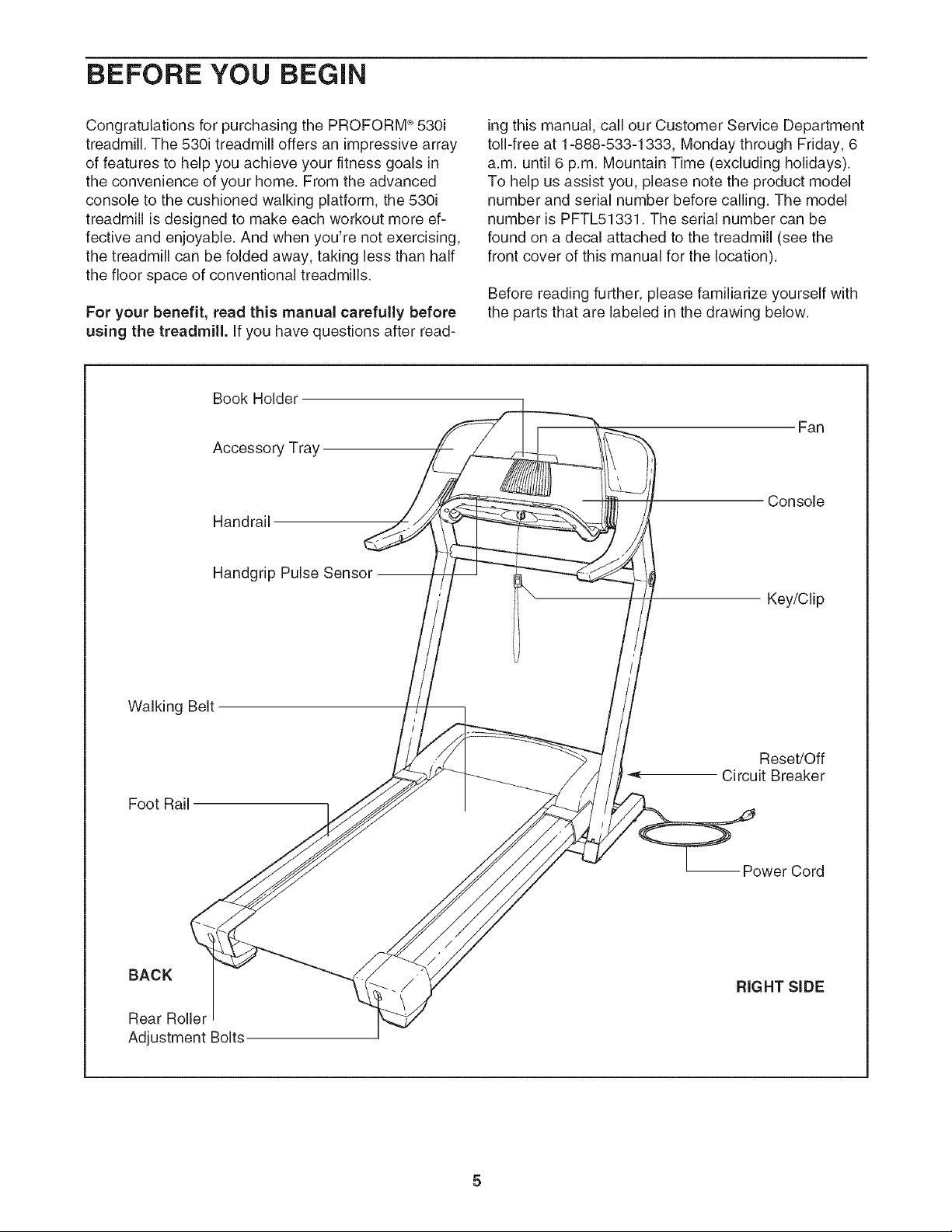
Before reading further, please familiarize yourself with
the parts that are labeled in the drawing below.
Book Holder
Accessory Tray
Handrail
Handgrip Pulse Sensor --
Walking Belt
J
Foot Rail
BACK
Rear Rolle_
Adjustment Bolts
Fan
Console
Key/Clip
Reset/Off
Circuit Breaker
-- Power Cord
RIGHT SiDE
5
ASSEMBLY
Assembly requires two persons. Set the treadmill in a cleared area and remove all packing materials. Do not
dispose of the packing materials until assembly is completed. Note: The underside of the treadmill walking belt is
coated with high-performance lubricant. During shipping, a small amount of lubricant may be transferred to the
top of the walking belt or the shipping carton. This is a normal condition and does not affect treadmill perfor-
mance, if there is lubricant on top of the walking belt, simply wipe off the lubricant with a soft cloth and a mild,
non-abrasive cleaner.
Assembly requires the included allen wr_ and your own phillips screwdriver (_]_======_,
wire cutters _ __, rubber mallet c::_=_, and adjustabJe wrench _.
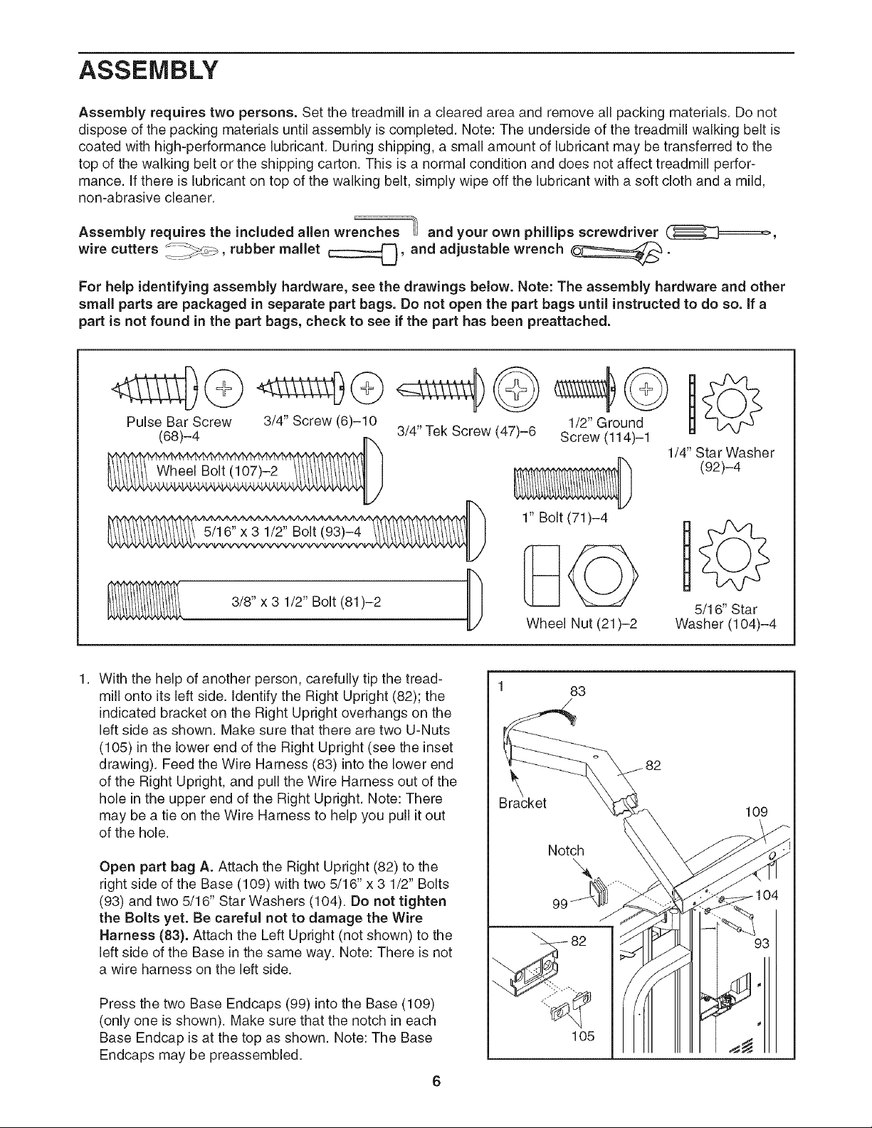
For heJp identifying assembly hardware, see the drawings below. Note: The assembly hardware and other
small parts are packaged in separate part bags. Do not open the part bags until instructed to do so. If a
part is not found in the part bags, check to see if the part has been preattached.
Pulse Bar Screw 3/4" Screw (6)-10
5/16" x 3 1/2" Bolt (93)-4
3/8" x 3 1/2" Bolt (81)-2
3/4" Tek Screw (47)-6 S1/r2e"wlrl__ d1
1/4" Star Washer
(92)-4
1" Bolt (71)-4
Wheel Nut (21)-2
DoO
5/1 6" Star
Washer (104)-4
With the help of another person, carefully tip the tread-
mill onto its left side. identify the Right Upright (82); the
indicated bracket on the Right Uptight overhangs on the
left side as shown. Make sure that there are two U-Nuts
(105) in the lower end of the Right Upright (see the inset
drawing). Feed the Wire Harness (83) into the lower end
of the Right Uptight, and pull the Wire Harness out of the
hole in the upper end of the Right Uptight. Note: There
may be a tie on the Wire Harness to help you pull it out
of the hole.
Open part bag A. Attach the Right Upright (82) to the
right side of the Base (109) with two 5/16" x 3 1/2" Bolts
(93) and two 5/16" Star Washers (104). Do not tighten
the Bolts yet. Be careful not to damage the Wire
Harness (83). Attach the Left Upright (not shown) to the
left side of the Base in the same way. Note: There is not
a wire harness on the left side.
Press the two Base Endcaps (99) into the Base (109)
(only one is shown). Make sure that the notch in each
Base Endcap is at the top as shown. Note: The Base
Endcaps may be preassembled.
6
83
/
Notch
105
109
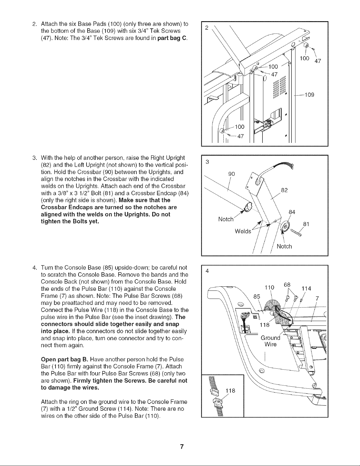
Attach the six Base Pads (100) (only three are shown) to
the bottom of the Base (109) with six 3/4" Tek Screws
(47). Note: The 3/4" Tek Screws are found in part bag C.
With the help of another person, raise the Right Upright
(82) and the Left Upright (not shown) to the vertical posi-
tion. Hold the Crossbar (90) between the Uprights, and
align the notches in the Crossbar with the indicated
welds on the Uprights. Attach each end of the Crossbar
with a 3/8"x 3 1/2" Bolt (81) and a Crossbar Endcap (84)
(only the right side is shown). Make sure that the
Crossbar Endcaps are turned so the notches are
aligned with the welds on the Uprights. Do not
tighten the Bolts yet.
90
Notch
82
84
Notch
81
Turn the Console Base (85) upside-down; be careful not
to scratch the Console Base. Remove the bands and the
Console Back (not shown) from the Console Base. Hold
the ends of the Pulse Bar (110) against the Console
Frame (7) as shown. Note: The Pulse Bar Screws (68)
may be preattached and may need to be removed.
Connect the Pulse Wire (118) in the Console Base to the
pulse wire in the Pulse Bar (see the inset drawing). The
connectors should slide together easily and snap
into place. If the connectors do not slide together easily
and snap into place, turn one connector and try to con-
nect them again.
Open part bag B. Have another person hold the Pulse
Bar (110) firmly against the Console Frame (7). Attach
the Pulse Bar with four Pulse Bar Screws (68) (only two
are shown). Firmly tighten the Screws. Be careful not
to damage the wires.
Attach the ring on the ground wire to the Console Frame
(7) with a 1/2" Ground Screw (114). Note: There are no
wires on the other side of the Pulse Bar (110).
110
85
68
114
/
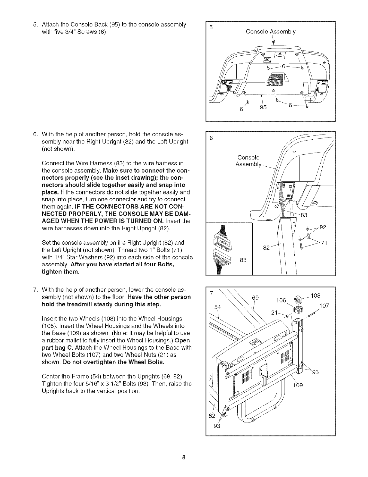
Attach the Console Back (95) to the console assembly
with five 3/4" Screws (6).
5
Console Assembly
With the help of another person, hold the console as-
sembly near the Right Upright (82) and the Left Upright
(not shown).
Connect the Wire Harness (83) to the wire harness in
the console assembly. Make sure to connect the con-
nectors properly (see the inset drawing); the con-
nectors should slide together easily and snap into
place. If the connectors do not slide together easily and
snap into place, turn one connector and try to connect
them again. IF THE CONNECTORS ARE NOT CON-
NECTED PROPERLY, THE CONSOLE MAY BE DAM-
AGED WHEN THE POWER iS TURNED ON. Insert the
wire harnesses down into the Right Upright (82).
Set the console assembly on the Right Upright (82) and
the Left Upright (not shown). Thread two 1" Bolts (71)
with 1/4" Star Washers (92) into each side of the console
assembly. After you have started all four Bolts,
tighten them.
With the help of another person, lower the console as-
sembly (not shown) to the floor. Have the other person
hold the treadmill steady during this step.
insert the two Wheels (108) into the Wheel Housings
(106). Insert the Wheel Housings and the Wheels into
the Base (109) as shown. (Note: It may be helpful to use
a rubber mallet to fully insert the Wheel Housings.) Open
part bag C. Attach the Wheel Housings to the Base with
two Wheel Bolts (107) and two Wheel Nuts (21) as
shown. Do not overtighten the Wheel Bolts.
Center the Frame (54) between the Uprights (69, 82).
Tighten the four 5/16" x 3 1/2" Bolts (93). Then, raise the
Uprights back to the vertical position.
Console
Assembl'
83
7
69 _108
106 107
54
21_ J
109
93
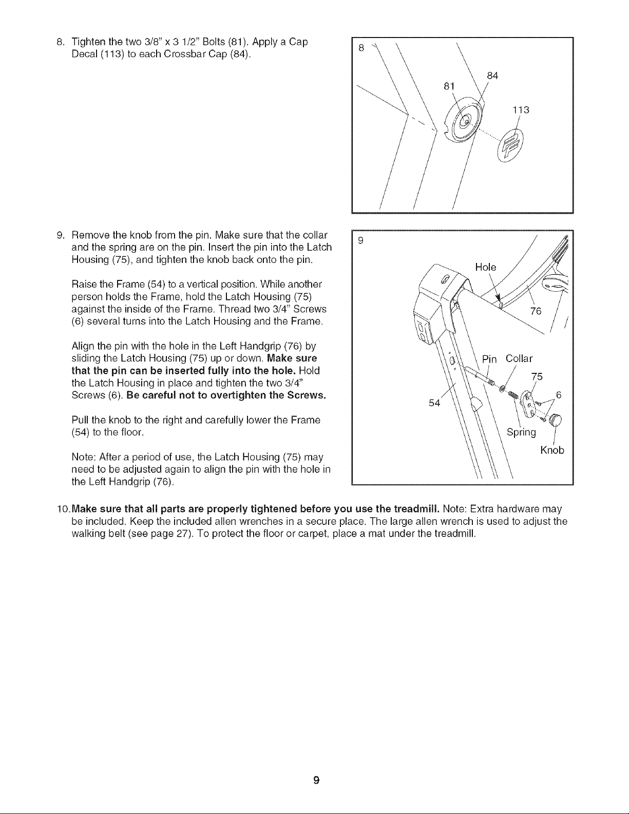
8. Tightenthetwo3/8"x 3 1/2"Bolts(81).ApplyaCap 8
Decal(113)toeachCrossbarCap(84).
81
84
113
Removetheknobfromthepin.Makesurethatthecollar
andthespringareonthepin.InsertthepinintotheLatch
Housing(75),andtightentheknobbackontothepin.
RaisetheFrame(54)toaverticalposition.Whileanother
personholdstheFrame,holdtheLatchHousing(75)
againsttheinsideoftheFrame.Threadtwo3/4"Screws
(6)severalturnsintotheLatchHousingandtheFrame.
AlignthepinwiththeholeintheLeftHandgrip(76)by
slidingtheLatchHousing(75)upordown.Makesure
that thepin can be inserted fully into the hole. Hold
the Latch Housing in place and tighten the two 3/4"
Screws (6). Be careful not to overtighten the Screws.
Pull the knob to the right and carefully lower the Frame
(54) to the floor.
Note: After a period of use, the Latch Housing (75) may
need to be adjusted again to align the pin with the hole in
the Left HandgrJp (76).
54
Hole
Pin
Collar
75
Spring
Knob
lO.Make sure that all parts are properly tightened before you use the treadmill. Note: Extra hardware may
be included. Keep the included allen wrenches in a secure place. The large allen wrench is used to adjust the
walking belt (see page 27). To protect the floor or carpet, place a mat under the treadmill.
TREADMILL OPERATION
THE PERFORMANT LUBE TM WALKING BELT
Your treadmill features a walking belt coated with
PERFORMANT LUBE TM, a high-performance lubricant.
iMPORTANT: Never apply silicone spray or other
substances to the walking belt or the walking plat-
form. Such substances will deteriorate the walking
belt and cause excessive wear.
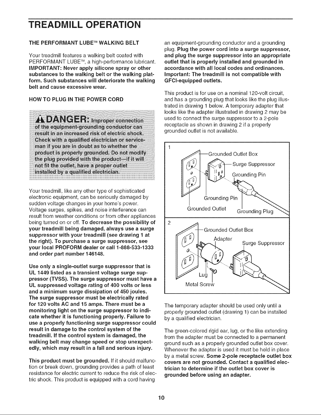
HOW TO PLUG iN THE POWER CORD
an equipment-grounding conductor and a grounding
plug. Plug the power cord into a surge suppressor,
and plug the surge suppressor into an appropriate
outlet that is properly installed and grounded in
accordance with all local codes and ordinances.
important: The treadmill is not compatible with
GFCl-equipped outlets.
This product is for use on a nominal 120-volt circuit,
and has a grounding plug that looks like the plug illus-
trated in drawing 1 below. A temporary adapter that
looks like the adapter illustrated in drawing 2 may be
used to connect the surge suppressor to a 2-pole
receptacle as shown in drawing 2 if a properly
grounded outlet is not available.
Your treadmill, like any other type of sophisticated
electronic equipment, can be seriously damaged by
sudden voltage changes in your home's power.
Voltage surges, spikes, and noise interference can
result from weather conditions or from other appliances
being turned on or off. To decrease the possibility of
your treadmill being damaged, always use a surge
suppressor with your treadmill (see drawing 1 at
the right). To purchase a surge suppressor, see
your local PROFORM dealer or call 1-888-533-1333
and order part number 146148.
Use only a single-ouUet surge suppressor that is
UL 1449 listed as a transient voltage surge sup-
pressor (TVSS). The surge suppressor must have a
UL suppressed voltage rating of 400 volts or less
and a minimum surge dissipation of 450 joules.
The surge suppressor must be electrically rated
for 120 volts AC and 15 amps. There must be a
monitoring light on the surge suppressor to indi-
cate whether it is functioning properly. Failure to
use a propedy functioning surge suppressor could
result in damage to the control system of the
treadmill, if the control system is damaged, the
walking belt may change speed or stop unexpect-
edly, which may result in a fall and serious injury.
This product must be grounded. If it should malfunc-
tion or break down, grounding provides a path of least
resistance for electric current to reduce the risk of elec-
tric shock. This product is equipped with a cord having
I
_J_Grounded Outlet Box
__"-I _ Surge Suppressor
'_ .......Grounding Pin
Grounding Pn_._
_rounded Outlet Grounding Plug"_
_rounded Outlet Box
Adapter
Surge Suppressor
The temporary adapter should be used only until a
properly grounded outlet (drawing 1) can be installed
by a qualified electrician.
The green-colored rigid ear, lug, or the like extending
from the adapter must be connected to a permanent
ground such as a properly grounded outlet box cover.
Whenever the adapter is used it must be held in place
by a metal screw. Some 2-pole receptacle outlet box
covers are not grounded. Contact a qualified elec-
trician to determine if the outlet box cover is
grounded before using an adapter.
10
/
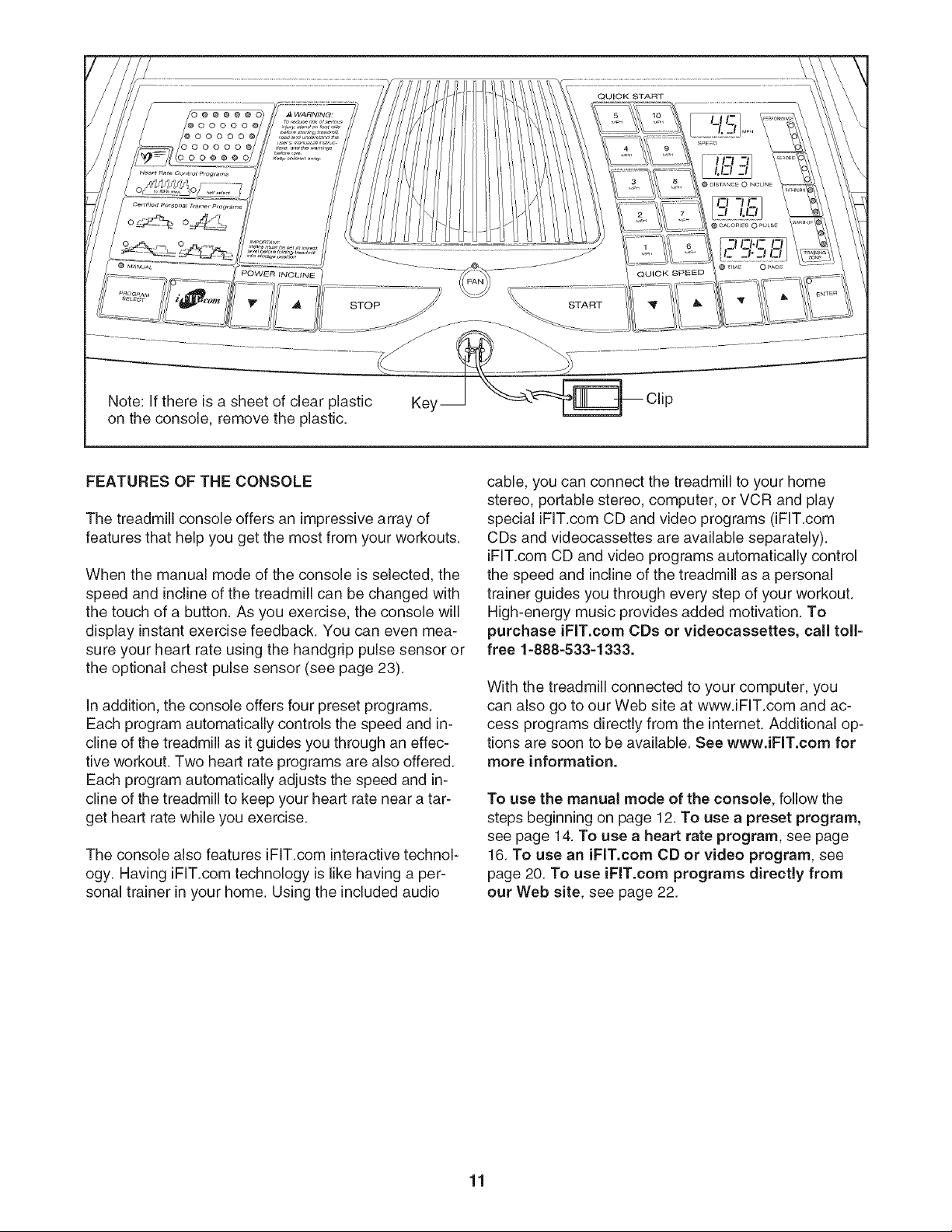
Note: If there is a sheet of clear plastic Key_ __ Clip
on the console, remove the plastic.
FEATURES OF THE CONSOLE
The treadmill console offers an impressive array of
features that help you get the most from your workouts.
When the manual mode of the console is selected, the
speed and incline of the treadmill can be changed with
the touch of a button. As you exercise, the console will
display instant exercise feedback. You can even mea-
sure your heart rate using the handgdp pulse sensor or
the optional chest pulse sensor (see page 23).
In addition, the console offers four preset programs.
Each program automatically controls the speed and in-
cline of the treadmill as it guides you through an effec-
tive workout. Two heart rate programs are also offered.
Each program automatically adjusts the speed and in-
cline of the treadmill to keep your heart rate near a tar-
get heart rate while you exercise.
The console also features iFIT.com interactive technol-
ogy. Having iFIT.com technology is like having a per-
sonal trainer in your home. Using the included audio
cable, you can connect the treadmill to your home
stereo, portable stereo, computer, or VCR and play
special iFIT.com CD and video programs (iFIT.com
CDs and videocassettes are available separately).
iFIT.com CD and video programs automatically control
the speed and incline of the treadmill as a personal
trainer guides you through every step of your workout.
High-energy music provides added motivation. To
purchase iFIT.com CDs or videocassettes, call toll-
free 1-888-533-1333.
With the treadmill connected to your computer, you
can also go to our Web site at www.iFIT.com and ac-
cess programs directly from the internet. Additional op-
tions are soon to be available. See www.iFIT.com for
more information.
To use the manual mode of the console, follow the
steps beginning on page 12. To use a preset program,
see page 14. To use a heart rate program, see page
16. To use an iFIT.com CD or video program, see
page 20. To use iFIT.com programs directly from
our Web site, see page 22.
11
HOWTO TURN ON THEPOWER
Plug in the power cord (see page 10).
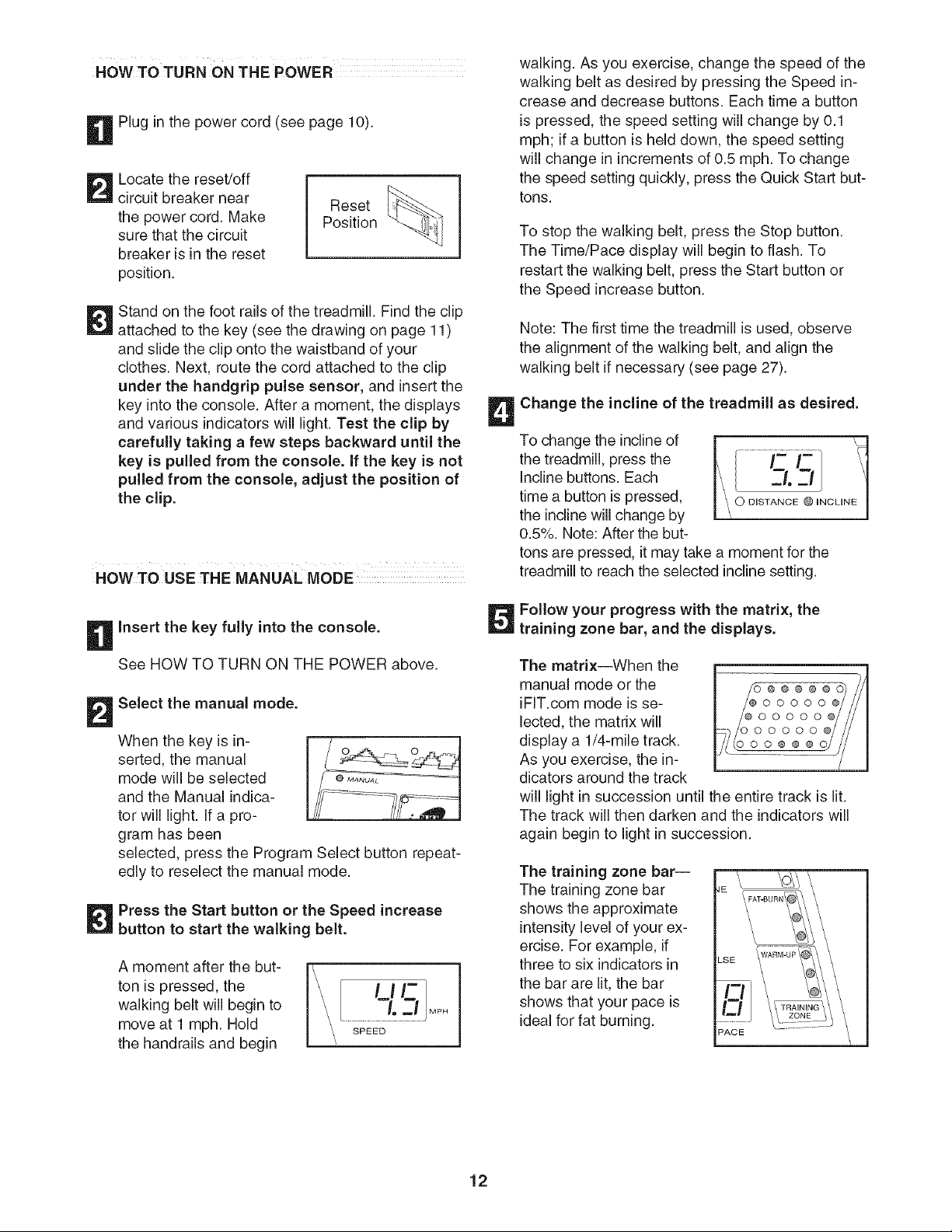
Locate the reset/off
circuit breaker near
the power cord. Make
sure that the circuit
breaker is in the reset
position.
Reset
Position
Stand on the foot rails of the treadmill. Find the clip
attached to the key (see the drawing on page 11)
and slide the clip onto the waistband of your
clothes. Next, route the cord attached to the clip
under the handgrip pulse sensor, and insert the
key into the console. After a moment, the displays
and various indicators will light. Test the clip by
carefully taking a few steps backward until the
key is pulled from the console. If the key is not
pulled from the console, adjust the position of
the clip.
HOWTO USETHE MANUALMODE i
Insert the key fully into the console.
See HOW TO TURN ON THE POWER above.
Select the manual mode.
When the key is in-
serted, the manual
mode will be selected
and the Manual indica-
tor will light. If a pro-
gram has been
selected, press the Program Select button repeat-
edly to reselect the manual mode.
Press the Start button or the Speed increase
button to start the walking belt.
A moment after the but-
ton is pressed, the
walking belt will begin to
move at 1 mph. Hold
the handrails and begin
walking. As you exercise, change the speed of the
walking belt as desired by pressing the Speed in-
crease and decrease buttons. Each time a button
is pressed, the speed setting will change by 0.1
mph; if a button is held down, the speed setting
will change in increments of 0.5 mph. To change
the speed setting quickly, press the Quick Start but-
tons.
To stop the walking belt, press the Stop button.
The Time/Pace display will begin to flash. To
restart the walking belt, press the Start button or
the Speed increase button.
Note: The first time the treadmill is used, observe
the alignment of the walking belt, and align the
walking belt if necessary (see page 27).
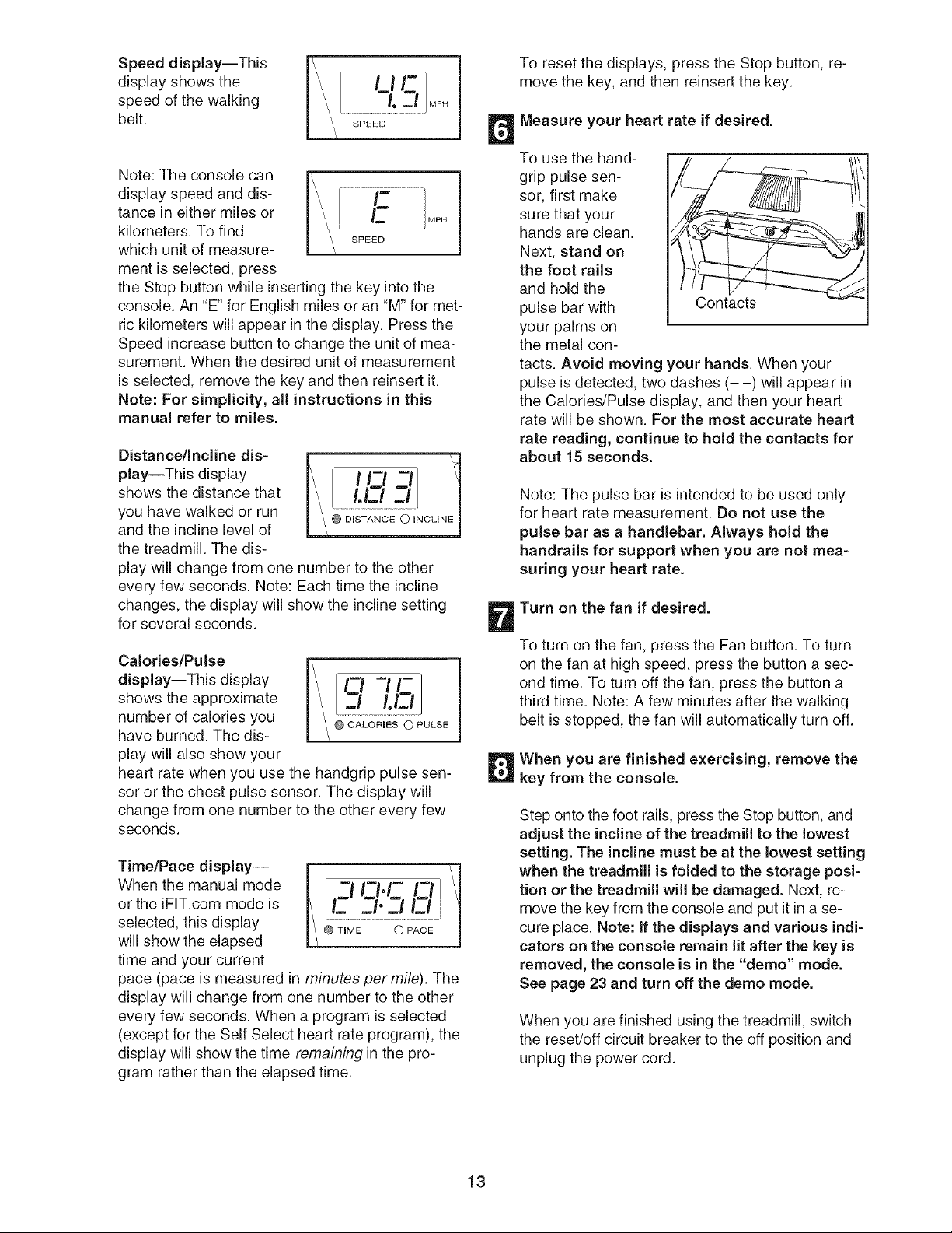
Change the incline of the treadmill as desired.
To change the incline of
the treadmill, press the
Incline buttons. Each
time a button is pressed,
the incline will change by
0.5%. Note: After the but-
tons are pressed, it may take a moment for the
treadmill to reach the selected incline setting.
Follow your progress with the matrix, the
training zone bar, and the displays.
The matrix--When the
manual mode or the
iFIT.com mode is se-
lected, the matrix will
display a 1/4-mile track.
As you exercise, the in-
dicators around the track
_ m
_@___@00000@
will light in succession until the entire track is lit.
The track will then darken and the indicators will
again begin to light in succession.
The training zone bar--
The training zone bar
shows the approximate
intensity level of your ex-
ercise. For example, if
three to six indicators in
the bar are lit, the bar
shows that your pace is
ideal for fat burning.
LSE
12
Speed display--This
display shows the
speed of the walking
belt.
..........i lP
................-l. --,
Note: The console can
display speed and dis-
tance in either miles or
kilometers. TO find
which unit of measure-
ment is selected, press
the stop button while inserting the key into the
console. An "E" for English miles or an "M" for met-
ric kilometers will appear in the display. Press the
Speed increase button to change the unit of mea-
surement. When the desired unit of measurement
is selected, remove the key and then reinsert it.
Note: For simplicity, all instructions in this
manual refer to miles.
Distance/Incline dis=
play--This display
shows the distance that
you have walked or run
and the incline level of
the treadmill. The dis-
play will change from one number to the other
every few seconds. Note: Each time the incline
changes, the display will show the incline setting
for several seconds.
Calories/Pulse
display--This display
shows the approximate
number of calories you
have burned. The dis-
play will also show your
heart rate when you use the handgrip pulse sen-
sor or the chest pulse sensor. The display will
change from one number to the other every few
seconds.
Time/Pace display--
When the manual mode
or the iFIT.com mode is
selected, this display
will show the elapsed
time and your current
-I I-I.I- I=
E. _1"_1 E.!
pace (pace is measured in minutes per mile). The
display will change from one number to the other
every few seconds. When a program is selected
(except for the Self Select heart rate program), the
display will show the time remaining in the pro-
gram rather than the elapsed time.
To reset the displays, press the Stop button, re-
move the key, and then reinsert the key.
Measure your heart rate if desired.
To use the hand-
grip pulse sen-
sor, first make
sure that your
hands are clean.
Next, stand on
the foot rails
and hold the
pulse bar with Contacts
your palms on
the metal con-
tacts. Avoid moving your hands. When your
pulse is detected, two dashes (- -) will appear in
the Calories/Pulse display, and then your heart
rate will be shown. For the most accurate heart
rate reading, continue to hold the contacts for
about 15 seconds.
Note: The pulse bar is intended to be used only
for heart rate measurement. Do not use the
pulse bar as a handlebar. Always hold the
handrails for support when you are not mea=
suring your heart rate.
Turn on the fan if desired.
To turn on the fan, press the Fan button. To turn
on the fan at high speed, press the button a sec-
ond time. To turn off the fan, press the button a
third time. Note: A few minutes after the walking
belt is stopped, the fan will automatically turn off.
When you are finished exercising, remove the
key from the console.
Step onto the foot rails, press the Stop button, and
adjust the incline of the treadmill to the lowest
setting. The incline must be at the lowest setting
when the treadmill is folded to the storage posi=
tion or the treadmill will be damaged. Next, re-
move the key from the console and put it in a se-
cure place. Note: If the displays and various indi=
cators on the console remain lit after the key is
removed, the console is in the "demo" mode.
See page 23 and turn off the demo mode.
When you are finished using the treadmill, switch
the reset/off circuit breaker to the off position and
unplug the power cord.
13
HOWTO USEPRESET PROGRAMS
insert the key fully into the console.
See HOW TO TURN ON THE POWER on
page 12.
Select one of the preset programs.
When the key is in-
serted, the manual
mode will be selected.
To select a personal
trainer program, press
the Program Select but-
ton repeatedly until one of the four personal
trainer program indicators lights.
The diagrams beside the personal trainer program
indicators show how the speed and incline of the
treadmill will change during the programs. When a
program is selected, the Speed display will flash
the maximum speed setting of the program for a
few seconds, and the Distance/incline display will
flash the maximum Incline setting. The Time/Pace
display will show how long the program will last.
The matrix will will
show the first four
speed settings of the
program.
OoOOOO I
Press the Start button or the Speed increase
button to start the program.
A moment after the button is pressed, the tread-
mill will automatically adjust to the first speed and
incline settings of the program. Hold the handrails
and begin walking.
Each program is divided into several time seg-
ments of different lengths. One speed setting and
one incline setting are programmed for each seg-
ment. Note: The same speed setting and/or in-
cline setting may be programmed for two or more
consecutive segments.
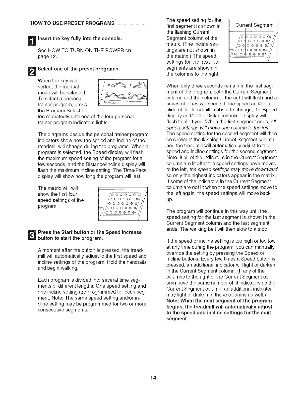
The speed setting for the
first segment is shown in
the flashing Current
Segment column of the
matrix. (The incline set-
tings are not shown in
the matrix.) The speed
settings for the next four
segments are shown in
the columns to the right.
Current Segment
DO0000
_000@
00@@
@@@
@@
When only three seconds remain in the first seg-
ment of the program, both the Current Segment
column and the column to the right will flash and a
series of tones will sound. Jfthe speed and/or in-
cline of the treadmill is about to change, the Speed
display and/or the Distance/incline display will
flash to alert you. When the first segment ends, all
speed settings will move one column to the left.
The speed setting for the second segment will then
be shown in the flashing Current Segment column
and the treadmill will automatically adjust to the
speed and incline settings for the second segment.
Note: If all of the indicators in the Current Segment
column are lit after the speed settings have moved
to the left, the speed settings may move downward
so only the highest indicators appear in the matrix.
Jfsome of the indicators in the Current Segment
column are not lit when the speed settings move to
the left again, the speed settings will move back
up.
The program will continue in this way until the
speed setting for the last segment is shown in the
Current Segment column and the last segment
ends. The walking belt will then slow to a stop.
Jfthe speed or incline setting is too high or too low
at any time during the program, you can manually
override the setting by pressing the Speed or
incline buttons. Every few times a Speed button is
pressed, an additional indicator will light or darken
in the Current Segment column. (if any of the
columns to the right of the Current Segment col-
umn have the same number of lit indicators as the
Current Segment column, an additional indicator
may light or darken in those columns as well.)
Note: When the next segment of the program
begins, the treadmill will automatically adjust
to the speed and incline settings for the next
segment.
14

To stop the program at any time, press the Stop
button. The Time/Pace display will begin to flash.
To restart the program, press the Start button or
the Speed increase button. The walking belt will
begin to move at 1 mph. When the next segment
of the program begins, the treadmill will automati-
cally adjust to the speed and incline settings for the
next segment.
Follow your progress with the displays.
See step 5 on page 12.
Measure your heart rate if desired.
See step 6 on page 13.
Turn on the fan if desired.
See step 7 on page 13.
When you are finished exercising, remove the
key from the console.
When the program ends, make sure that the in-
cline of the treadmill is at the lowest setting.
Next, remove the key from the console and put it in
a secure place. Note: If the displays and various
indicators on the console remain lit after the
key is removed, the console is in the "demo"
mode. See page 23 and turn off the demo mode.
When you are finished using the treadmill, switch
the reset/off circuit breaker to the off position and
unplug the power cord.
15
HOW TO USE HEART RATE PROGRAMS
Put on the optional chest pulse sensor.
You must wear the optional chest pulse sensor
(see page 23) to use a heart rate program. See
the instructions included with the chest pulse
sensor.
insert the key fully into the console.
See HOW TO TURN ON THE POWER on
page 12.
Select a heart rate program.
When the key is in-
serted, the manual
mode will be selected.
To select a heart rate
program, press the
Program Select button
gram_
[
repeatedly until one of the two heart rate program
indicators lights.
The diagrams beside the heart rate program indi-
cators show how the target heart rate will change
during the programs. During the 85% Max pro-
gram, your heart rate will reach approximately
85% of your estimated maximum heart rate; dur-
ing the Self Select program, your heart rate will re-
main near a level that you select. Note: Your esti-
mated maximum heart rate is determined by sub-
tracting your age from 220. For example, if you
are 30 years old, your estimated maximum heart
rate is 190 beats per minute (220 - 30 = 190).
During heart rate pro-
grams, the matrix will
show a moving graphic
that represents your
heart rate. Each time a
heartbeat is detected,
an additional peak will
appear.
o oooo
oO OoOO
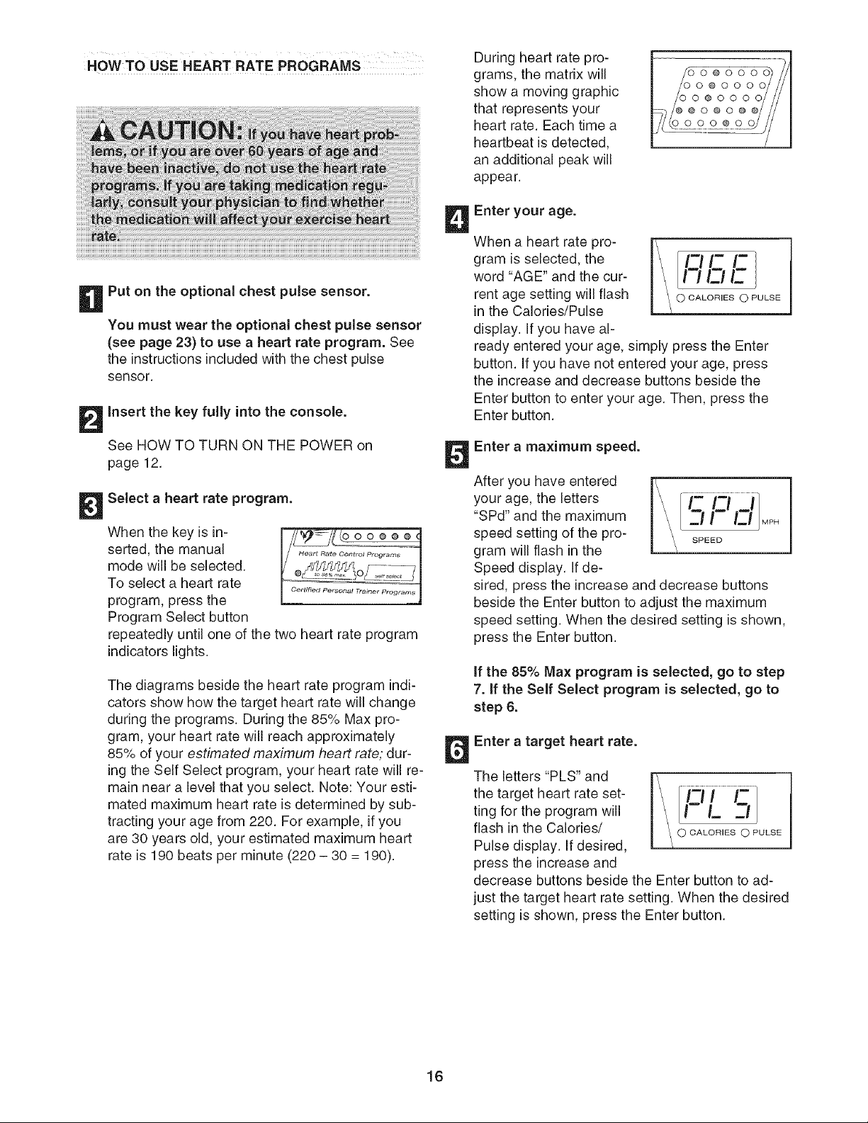
Enter your age.
When a heart rate pro-
gram is selected, the
word "AGE" and the cur-
rent age setting will flash
in the Calories/Pulse
display. If you have al-
l-_ii-l-
I\ in r_lr_
ready entered your age, simply press the Enter
button. If you have not entered your age, press
the increase and decrease buttons beside the
Enter button to enter your age. Then, press the
Enter button.
Enter a maximum speed.
After you have entered
your age, the letters
"SPd" and the maximum
speed setting of the pro-
gram will flash in the
Speed display. If de-
\ itt i
n M,.
sired, press the increase and decrease buttons
beside the Enter button to adjust the maximum
speed setting. When the desired setting is shown,
press the Enter button.
if the 85% Max program is selected, go to step
7. if the Self Select program is selected, go to
step 6.
Enter a target heart rate.
The letters "PLS" and
the target heart rate set-
ting for the program will
flash in the Calories/
Pulse display. If desired,
press the increase and
decrease buttons beside the Enter button to ad-
just the target heart rate setting. When the desired
setting is shown, press the Enter button.
16

Press the Start button or the Speed increase
button to start the program.
A moment after the button is pressed, the tread-
mill will automatically adjust to the first speed and
incline settings of the program. Hold the handrails
and begin walking.
Each heart rate program is divided into several time
segments of different lengths. One target heart rate
is programmed for each segment. Note: If the Self
Select program is selected, the same target heart
rate is programmed for all segments.
During each segment, the console will regularly
compare your heart rate to the current target heart
rate. If your heart rate is too far below or above
the target heart rate, the speed of the treadmill will
automatically increase or decrease to bring your
heart rate closer to the target heart rate. If the
speed reaches the maximum speed setting of the
program (see step 5 on page 16) and your heart
rate is still too far below the current target heart
rate, the incline of the treadmill will also increase
to bring your heart rate closer to the target heart
rate.
During the last three seconds of each segment, a
series of tones will sound and the Speed display
and the Distance/Incline display will flash.
The program will continue until the last segment
ends. The walking belt will then slow to a stop.
If the speed or incline setting is too high or too low
at any time during the program, you can adjust the
setting with the Speed or Incline buttons. However,
each time the console compares your heart rate to
the current target heart rate, the speed and/or in-
cline of the treadmill may automatically change to
bring your heart rate closer to the target heart rate.
If your pulse is not detected during the program,
the letters "PLS" will flash in the Calories/Pulse
display and the speed and incline of the treadmill
may automatically decrease until your pulse is de-
tected. If this occurs, see the instructions included
with the optional chest pulse sensor.
To stop the program at any time, press the Stop
button. Heart rate programs cannot be stopped
temporarily and then restarted. To use a heart rate
program again, reselect the program and start it at
the beginning.
Follow your progress with the displays.
See step 5 on page 12.
Turn on the fan if desired.
See step 7 on page 13.
When you are finished exercising, remove the
key from the console.
See step 7 on page 15.
17
HOW TO CONNECT YOUR PORTABLE STEREO
To use iFIT.com CDs, the treadmill must be connected
to your portable CD player, portable stereo, home
stereo, or computer with CD player. See pages 18 and
19 for connecting instructions. To use iFIT.com video-
cassettes, the treadmill must be connected to your
VCR. See page 20 for connecting instructions. To use
iFIT.com programs directly from our internet site,
the treadmill must be connected to your home com-
puter. See page 19 for connecting instructions.
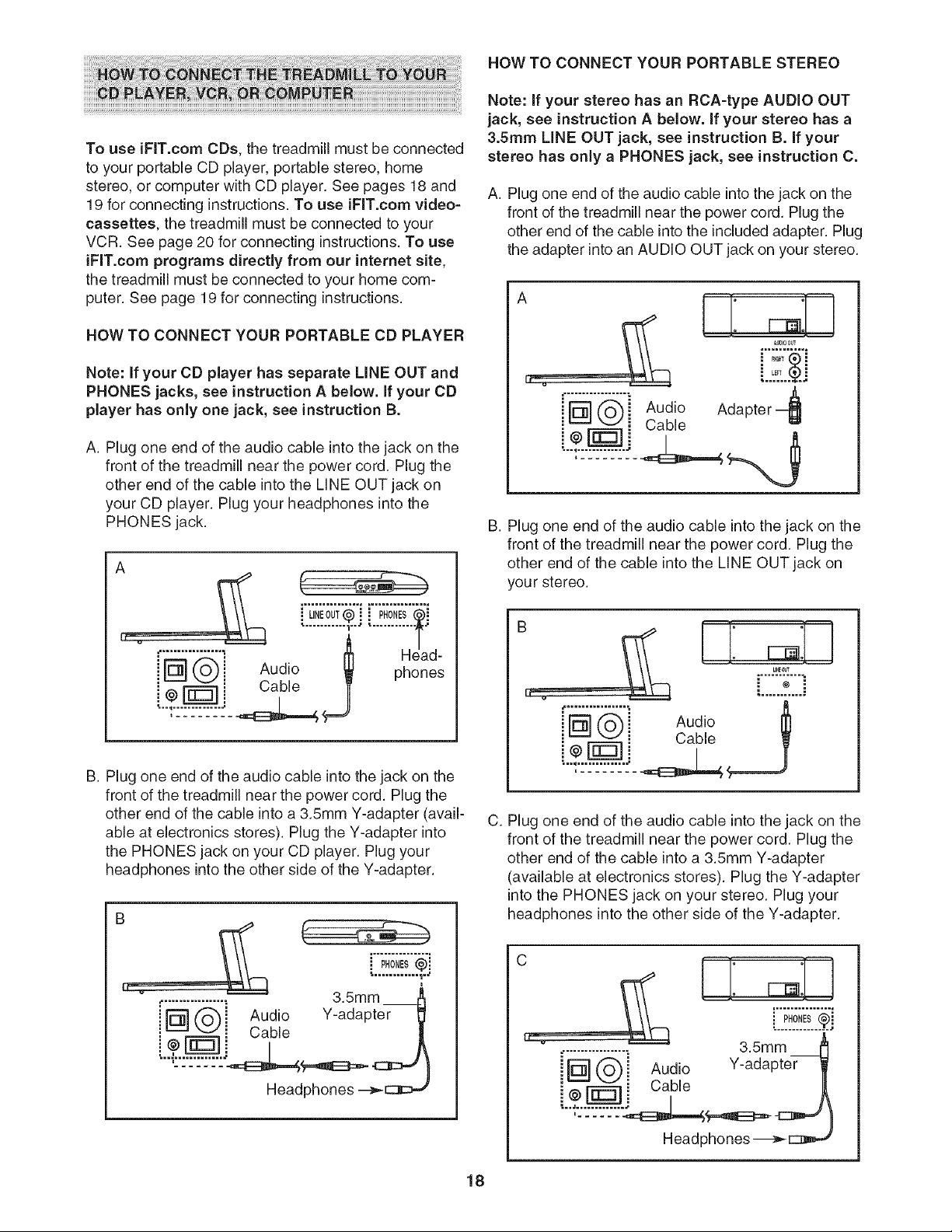
HOW TO CONNECT YOUR PORTABLE CD PLAYER
Note: if your CD player has separate UNE OUT and
PHONES jacks, see instruction A below. If your CD
player has only one jack, see instruction B.
A. Plug one end of the audio cable into the jack on the
front of the treadmill near the power cord. Plug the
other end of the cable into the LINE OUT jack on
your CD player. Plug your headphones into the
PHONES jack.
c,__,
...............i.....................
iH@i W £o n de;
!--:-:---:-:---:-].
B. Plug one end of the audio cable into the jack on the
front of the treadmill near the power cord. Plug the
other end of the cable into a 3.5mm Y-adapter (avail-
able at electronics stores). Plug the Y-adapter into
the PHONES jack on your CD player. Plug your
headphones into the other side of the Y-adapter.
Headphones
Note: If your stereo has an RCA-type AUDIO OUT
jack, see instruction A below, if your stereo has a
3.5ram LiNE OUT jack, see instruction B. If your
stereo has only a PHONES jack, see instruction C.
A. Plug one end of the audio cable into the jack on the
front of the treadmill near the power cord. Plug the
other end of the cable into the included adapter. Plug
the adapter into an AUDIO OUT jack on your stereo.
Aud,o
Cable
....*.?._.%..
• LEFT
Adapter _
B. Plug one end of the audio cable into the jack on the
front of the treadmill near the power cord. Plug the
other end of the cable into the LINE OUT jack on
you r stereo.
,u0,o
CCY
C. Plug one end of the audio cable into the jack on the
front of the treadmill near the power cord. Plug the
other end of the cable into a 3.5mm Y-adapter
(available at electronics stores). Plug the Y-adapter
into the PHONES jack on your stereo. Plug your
headphones into the other side of the Y-adapter.
c L[: =:U
i p,o,E ..¢.]
................._ 3.5mm
[D] ('_ i Audio Y-adapter _
7-r i Cable
Headphones-_-_
18
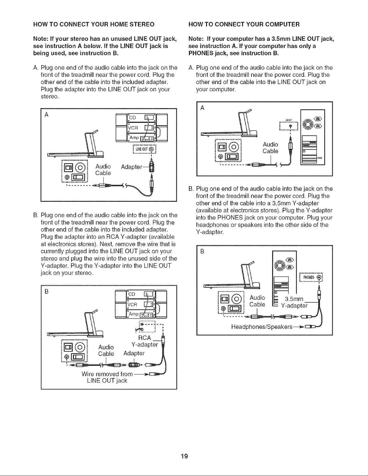
HOW TO CONNECT YOUR HOME STEREO HOW TO CONNECT YOUR COMPUTER
Note: if your stereo has an unused LiNE OUT jack,
see instruction A below. If the LiNE OUT jack is
being used, see instruction B.
A. Plug one end of the audio cable into the jack on the
front of the treadmill near the power cord. Plug the
other end of the cable into the included adapter.
Plug the adapter into the LINE OUT jack on your
stereo.
@@ Audio
Cable
........ m
........... jn..
i
Adapter_
B. Plug one end of the audio cable into the jack on the
front of the treadmill near the power cord. Plug the
other end of the cable into the included adapter.
Plug the adapter into an RCA Y-adapter (available
at electronics stores). Next, remove the wire that is
currently plugged into the LINE OUT jack on your
stereo and plug the wire into the unused side of the
Y-adapter. Plug the Y-adapter into the LINE OUT
jack on your stereo.
m CD ,m
Amp_
RCA
• Y-adapter
Aud,o
_ _ i Cable Adapter
Wire removed from _
LINE OUT jack
Note: if your computer has a 3.5mm LiNE OUT jack,
see instruction A. If your computer has only a
PHONES jack, see instruction B.
A. Plug one end of the audio cable into the jack on the
front of the treadmill near the power cord. Plug the
other end of the cable into the LINE OUT jack on
you r computer.
A
i
B. Plug one end of the audio cable into the jack on the
front of the treadmill near the power cord. Plug the
other end of the cable into a 3.5mm Y-adapter
(available at electronics stores). Plug the Y-adapter
into the PHONES jack on your computer. Plug your
headphones or s )eakers into the other side of the
Y-adapter.
B
(Sbi Audio _=3.smm
@,_F-_ i Cable - Y-adapter
....,,............J__
Headphones/S peakers-_
19
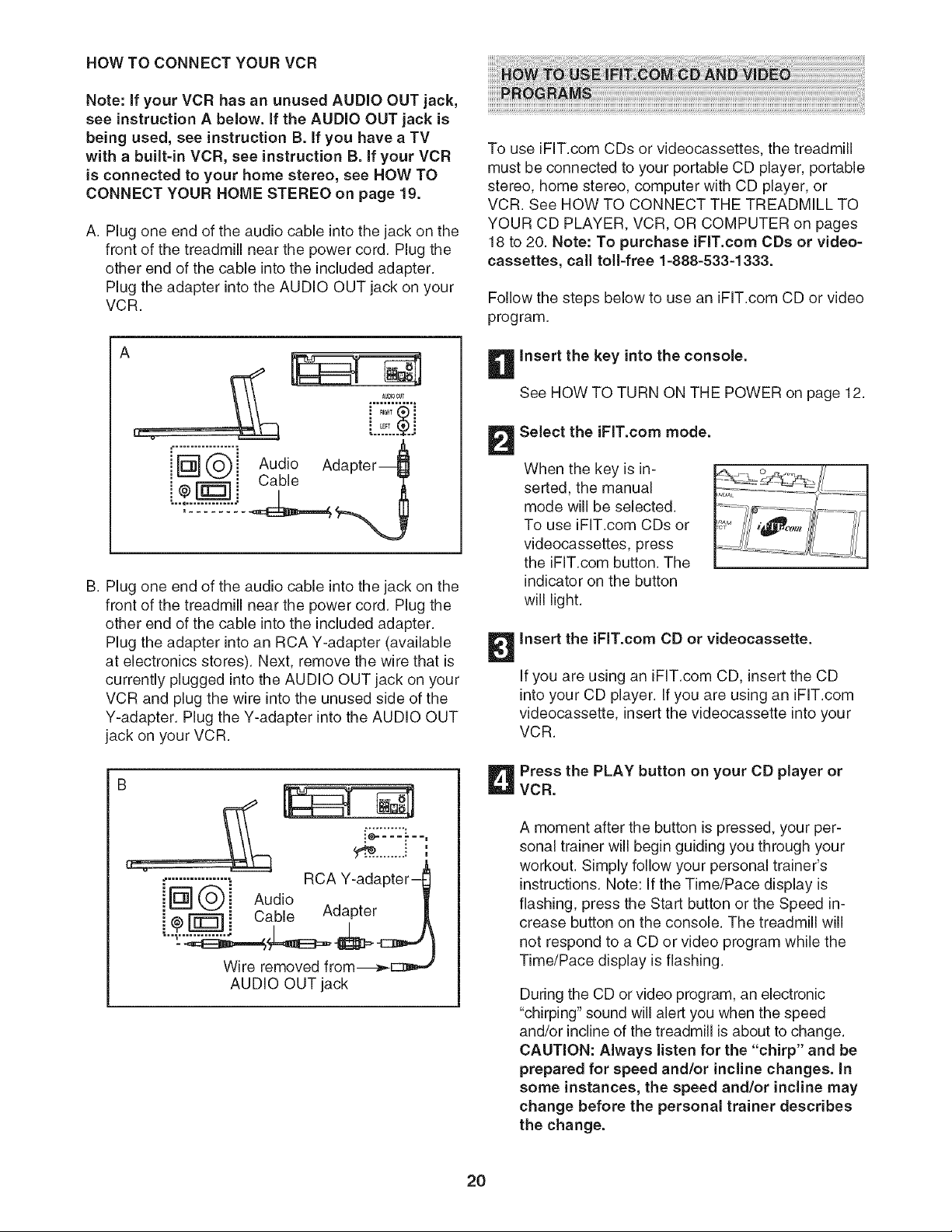
HOW TO CONNECT YOUR VCR
Note: if your VCR has an unused AUDIO OUT jack,
see instruction A below, if the AUDIO OUT jack is
being used, see instruction B. If you have a TV
with a built=in VCR, see instruction B. if your VCR
is connected to your home stereo, see HOW TO
CONNECT YOUR HOME STEREO on page 19.
A. Plug one end of the audio cable into the jack on the
front of the treadmill near the power cord. Plug the
other end of the cable into the included adapter.
Plug the adapter into the AUDIO OUT jack on your
VCR.
@@ Audio
Cable
I .........
...:._.°.%..
Ada
B. Plug one end of the audio cable into the jack on the
front of the treadmill near the power cord. Plug the
other end of the cable into the included adapter.
Plug the adapter into an RCA Y-adapter (available
at electronics stores). Next, remove the wire that is
currently plugged into the AUDIO OUT jack on your
VCR and plug the wire into the unused side of the
Y-adapter. Plug the Y-adapter into the AUDIO OUT
jack on your VCR.
B
[_::--_..,
RCA Y-adapter-
@Qi Audio
@ _ _ Cable Adapter
Wire removed from---_
AUDIO OUT jack
To use iFIT.com CDs or videocassettes, the treadmill
must be connected to your portable CD player, portable
stereo, home stereo, computer with CD player, or
VCR. See HOW TO CONNECT THE TREADMILL TO
YOUR CD PLAYER, VCR, OR COMPUTER on pages
18 to 20. Note: To purchase iFIT.com CDs or video-
cassettes, call toll-free 1-888-533-1333.
Follow the steps below to use an iFIT.com CD or video
program.
insert the key into the console.
See HOWTO TURN ON THE POWER on page 12.
Select the iFIT.com mode.
When the key is in-
serted, the manual
mode will be selected.
To use iFIT.com CDs or
videocassettes, press
the iFIT.com button. The
indicator on the button
will light.
insert the iFIT.com CD or videocassette.
If you are using an iFIT.com CD, insert the CD
into your CD player. If you are using an iFIT.com
videocassette, insert the videocassette into your
VCR.
Press the PLAY button on your CD player or
VCR.
A moment after the button is pressed, your per-
sonal trainer will begin guiding you through your
workout. Simply follow your personal trainer's
instructions. Note: If the Time/Pace display is
flashing, press the Start button or the Speed in-
crease button on the console. The treadmill will
not respond to a CD or video program while the
Time/Pace display is flashing.
During the CD or video program, an electronic
"chirping" sound will alert you when the speed
and/or incline of the treadmill is about to change.
CAUTION: Always listen for the "chirp" and be
prepared for speed and/or incline changes, in
some instances, the speed and/or incline may
change before the personal trainer describes
the change.
2O

If the speed or incline settings are too high or too
low, you can manually override the settings at any
time by pressing the Speed or Incline buttons on
the console. However, when the next "chirp" is
heard, the speed and/or incline will change to
the next settings of the CD or video program.
To stop the walking belt at any time, press the
Stop button on the console. The Time/Pace dis-
play will begin to flash. To restart the program,
press the Start button or the Speed increase but-
ton. After a moment, the walking belt will begin to
move at 1 mph. When the next "chirp" is heard,
the speed and incline will change to the next
settings of the CD or video program.
When the CD or video program is completed, the
walking belt will stop and the Time/Pace display
will begin to flash. Note: To use another CD or
video program, press the Stop button or remove
the key and go to step 1 on page 20.
Note: If the speed or incline of the treadmill
does not change when a "chirp" is heard:
, Make sure that the iFIT.com indicator is lit and
that the Time/Pace display is not flashing, if
the TimelPace display is flashing, press the
Start button or the Speed increase button on
the console.
, Adjust the volume of your CD player or VCR.
if the volume is too high or too low, the con-
sole may not detect the program signals.
, Make sure that the audio cable is properly
connected, that it is fully plugged in, and that
it is not wrapped around a power cord.
, if you are using your portable CD player and
the CD skips, set the CD player on the floor or
another flat surface instead of on the console.
Follow your progress with the matrix, the train-
ing zone bar, and the displays.
See step 5 on page 12.
Measure your heart rate if desired.
See step 6 on page 13.
Turn on the fan if desired.
See step 7 on page 13.
When you are finished exercising, remove the
key from the console.
See step 7 on page 15.
CAUTION: Always remove iFIT.com CDs and
videocassettes from your CD player and VCR
when you are finished using them.
21
To use programs from our Web site, the treadmill must
be connected to your home computer. See HOW TO
CONNECT YOUR COMPUTER on page 19. In addi-
tion, you must have an internet connection and an in-
ternet service provider. A list of specific system re-
quirements is found on our Web site.
Follow the steps below to use a program from our
Web site.
insert the key into the console.
See HOW TO TURN ON THE POWER on page 12.
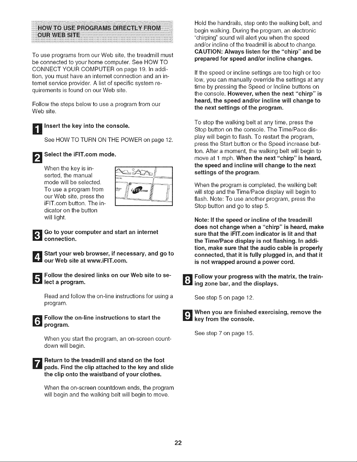
Select the iFIT.com mode.
When the key is in-
serted, the manual
mode will be selected.
To use a program from
our Web site, press the
iFIT.com button. The in-
dicator on the button
will light.
Go to your computer and start an internet
connection.
Start your web browser, if necessary, and go to
our Web site at www.iFIT.com.
Follow the desired links on our Web site to se=
lect a program.
Read and follow the on-line instructions for using a
program.
Follow the on=line instructions to start the
program.
When you start the program, an on-screen count-
down will begin.
Return to the treadmill and stand on the foot
pads. Find the clip attached to the key and slide
the clip onto the waistband of your clothes.
When the on-screen countdown ends, the program
will begin and the walking belt will begin to move.
Hold the handrails, step onto the walking belt, and
begin walking. During the program, an electronic
"chirping" sound will alert you when the speed
and/or incline of the treadmill is about to change.
CAUTION: Always listen for the "chirp" and be
prepared for speed and/or incline changes.
If the speed or incline settings are too high or too
low, you can manually override the settings at any
time by pressing the Speed or Incline buttons on
the console. However, when the next "chirp" is
heard, the speed and/or incline will change to
the next settings of the program.
To stop the walking belt at any time, press the
Stop button on the console. The Time/Pace dis-
play will begin to flash. To restart the program,
press the Start button or the Speed increase but-
ton. After a moment, the walking belt will begin to
move at 1 mph. When the next "chirp" is heard,
the speed and incline will change to the next
settings of the program.
When the program is completed, the walking belt
will stop and the Time/Pace display will begin to
flash. Note: To use another program, press the
Stop button and go to step 5.
Note: if the speed or incline of the treadmill
does not change when a "chirp" is heard, make
sure that the iFIT.com indicator is lit and that
the TimelPace display is not flashing, in addi-
tion, make sure that the audio cable is properly
connected, that it is fully plugged in, and that it
is not wrapped around a power cord.
Follow your progress with the matrix, the train=
mg zone bar, and the displays.
See step 5 on page 12.
When you are finished exercising, remove the
key from the console.
See step 7 on page 15.
22
THE iNFORMATiON MODE/DEMO MODE THE OPTIONAL CHEST PULSE SENSOR
The console features an information mode that keeps
track of total number of miles that the walking belt has
moved and the total number of hours that the treadmill
has been used. The information mode also allows you
to switch the console from miles to kilometers. In addi-
tion, the information mode allows you to turn on and
turn off the demo mode.
To select the information mode, hold down the Stop
button while inserting the key into the console. When
the information mode is selected, the following informa-
tion will be shown:
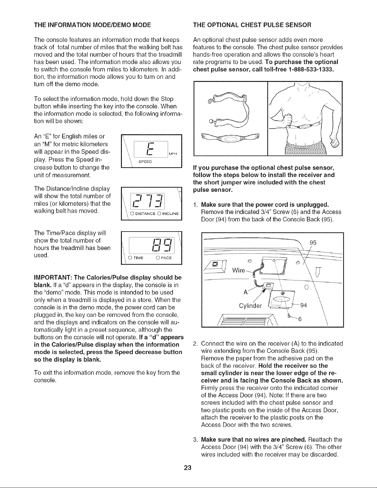
An "E" for English miles or
an "M" for metric kilometers
will appear in the Speed dis-
play. Press the Speed in-
crease button to change the
unit of measurement.
ThoO,stance/,nc,,neO,sp,ay
will show the total number of
miles (or kilometers) that the
walking belt has moved.
The Time/Pace display will
show the total number of
hours the treadmill has been
used.
q
, i_--io /
\ o_-i/
iMPORTANT: The Calories/Pulse display should be
blank. If a "d" appears in the display, the console is in
the "demo" mode. This mode is intended to be used
only when a treadmill is displayed in a store. When the
console is in the demo mode, the power cord can be
plugged in, the key can be removed from the console,
and the displays and indicators on the console will au-
tomatically light in a preset sequence, although the
buttons on the console will not operate. If a "d" appears
in the Calories/Pulse display when the information
mode is selected, press the Speed decrease button
so the display is blank.
To exit the information mode, remove the key from the
console.
An optional chest pulse sensor adds even more
features to the console. The chest pulse sensor provides
hands-free operation and allows the console's heart
rate programs to be used. To purchase the optional
chest pulse sensor, call toll-free 1-888-533-1333.
If you purchase the optional chest pulse sensor,
follow the steps below to install the receiver and
the short jumper wire included with the chest
pulse sensor.
1. Make sure that the power cord is unplugged.
Remove the indicated 3/4" Screw (6) and the Access
Door (94) from the back of the Console Back (95).
2.
Connect the wire on the receiver (A) to the indicated
wire extending from the Console Back (95).
Remove the paper from the adhesive pad on the
back of the receiver. Hold the receiver so the
small cylinder is near the lower edge of the re-
ceiver and is facing the Console Back as shown.
Firmly press the receiver onto the indicated corner
of the Access Door (94). Note: If there are two
screws included with the chest pulse sensor and
two plastic posts on the inside of the Access Door,
attach the receiver to the plastic posts on the
Access Door with the two screws.
3. Make sure that no wires are pinched. Reattach the
Access Door (94) with the 3/4" Screw (6). The other
wires included with the receiver may be discarded.
23
HOW TO FOLD AND MOVE THE TREADMILL
HOW TO FOLD THE TREADMILL FOR STORAGE
Before folding the treadmill, adjust the incline to the
lowest position, if this is not done, the treadmill may be
permanently damaged. Next, unplug the power cord.
CAUTION: You must be able to safely lift 45 pounds (20
kg) to raise, lower, or move the treadmill.
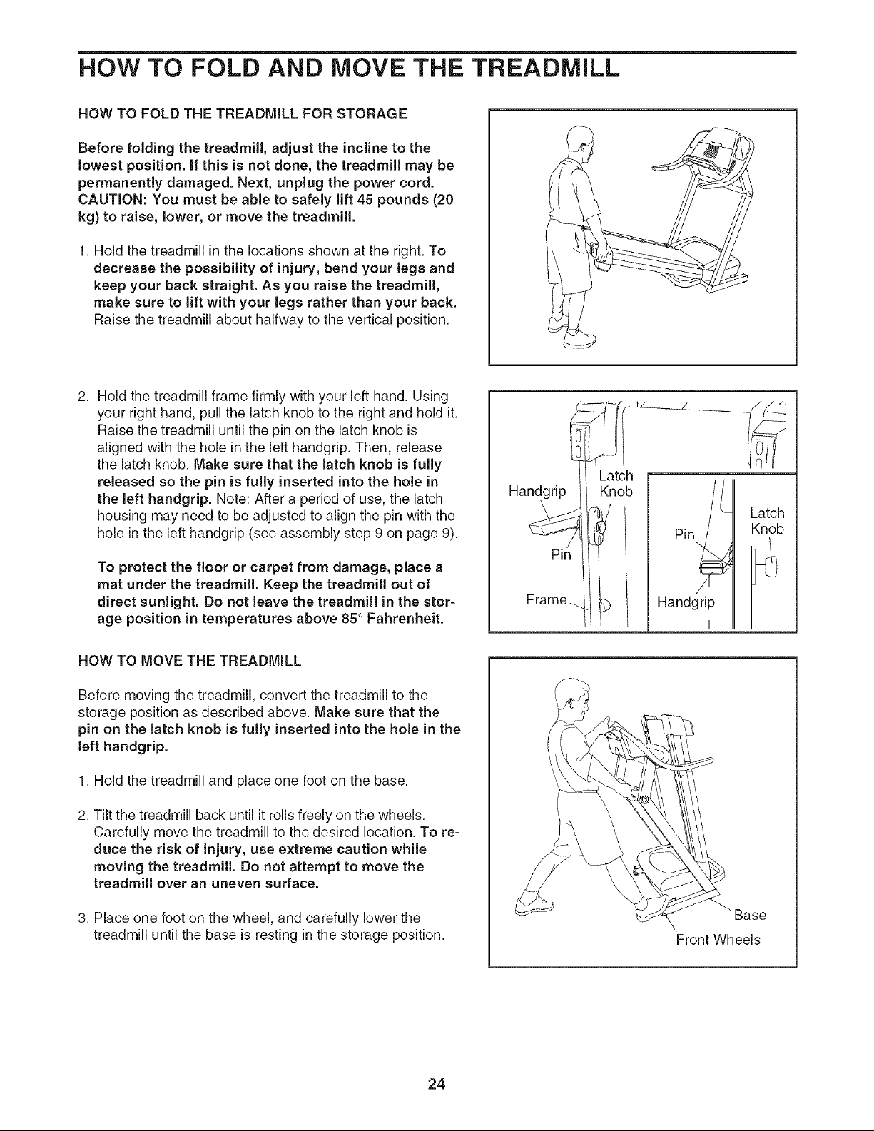
1. Hold the treadmill in the locations shown at the right. To
decrease the possibility of injury, bend your legs and
keep your back straight. As you raise the treadmill,
make sure to lift with your legs rather than your back.
Raise the treadmill about halfway to the vertical position.
2. Hold the treadmill frame firmly with your left hand. Using
your right hand, pull the latch knob to the right and hold it.
Raise the treadmill until the pin on the latch knob is
aligned with the hole in the left handgrip. Then, release
the latch knob. Make sure that the latch knob is fully
released so the pin is fully inserted into the hole in
the left handgrip. Note: After a period of use, the latch
housing may need to be adjusted to align the pin with the
hole in the left handgrip (see assembly step 9 on page 9).
To protect the floor or carpet from damage, place a
mat under the treadmill. Keep the treadmill out of
direct sunlight. Do not leave the treadmill in the stor=
age position in temperatures above 85° Fahrenheit.
HOW TO MOVE THE TREADMILL
Before moving the treadmill, convert the treadmill to the
storage position as described above. Make sure that the
pin on the latch knob is fully inserted into the hole in the
left handgrip.
1. Hold the treadmill and place one foot on the base.
2. Tilt the treadmill back until it rolls freely on the wheels.
Carefully move the treadmill to the desired location. To re-
duce the risk of injury, use extreme caution while
moving the treadmill. Do not attempt to move the
treadmill over an uneven surface.
3. Place one foot on the wheel, and carefully lower the
treadmill until the base is resting in the storage position.
Front Wheels
24
HOWTOLOWERTHETREADMILLFORUSE
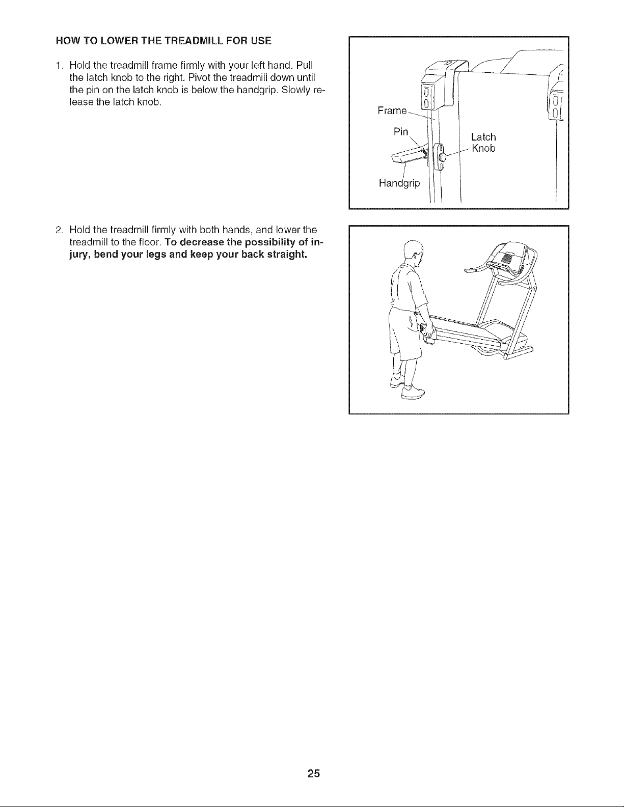
1. Hold the treadmill frame firmly with your left hand. Pull
the latch knob to the right. Pivot the treadmill down until
the pin on the latch knob is below the handgrip. Slowly re-
lease the latch knob.
Pin
Handgrip
Latch
J Knob
2. Hold the treadmill firmly with both hands, and lower the
treadmill to the floor. To decrease the possibility of in-
jury, bend your legs and keep your back straight.
25
TROUBLESHOOTING
Most treadmill problems can be solved by following the instructions below, if further assistance is
needed, please call our Customer Service Department toll=free at 1=888=533=1333, Monday through Friday,
6 a.m. until 6 p.m. Mountain Time (excluding holidays).
PROBLEM: The power does not turn on
SOLUTION: a.
Make sure that the power cord is plugged into a surge suppressor, and that the surge suppressor
is plugged into a properly grounded outlet (see page 10). Use only a single-outlet surge suppres-
sor that meets all of the specifications described on page 10. Important: The treadmill is not com-
patible with GFCl-equipped outlets.
b. Make sure that the key is fully inserted into the console.
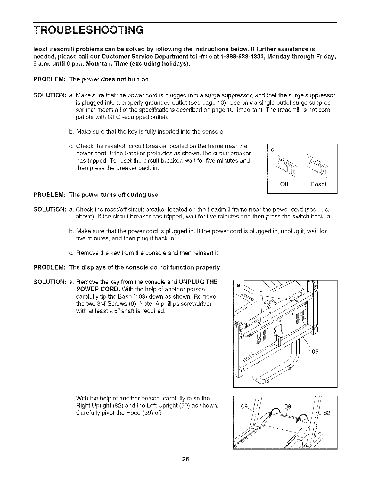
C.
Check the reset/off circuit breaker located on the frame near the
power cord. If the breaker protrudes as shown, the circuit breaker
has tripped. To reset the circuit breaker, wait for five minutes and
then press the breaker back in.
PROBLEM: The power turns off during use
Off Reset
SOLUTION: a. Check the reset/off circuit breaker located on the treadmill frame near the power cord (see 1. c.
above). If the circuit breaker has tripped, wait for five minutes and then press the switch back in.
b. Make sure that the power cord is plugged in. If the power cord is plugged in, unplug it, wait for
five minutes, and then plug it back in.
c. Remove the key from the console and then reinsert it.
PROBLEM: The displays of the console do not function properly
SOLUTION: a. Remove the key from the console and UNPLUG THE
POWER CORD. With the help of another person,
carefully tip the Base (109) down as shown. Remove
the two 3/4"Screws (6). Note: A phillips screwdriver
with at least a 5" shaft is required.
109
With the help of another person, carefully raise the
Right Upright (82) and the Left Upright (69) as shown.
Carefully pivot the Hood (39) off.
26
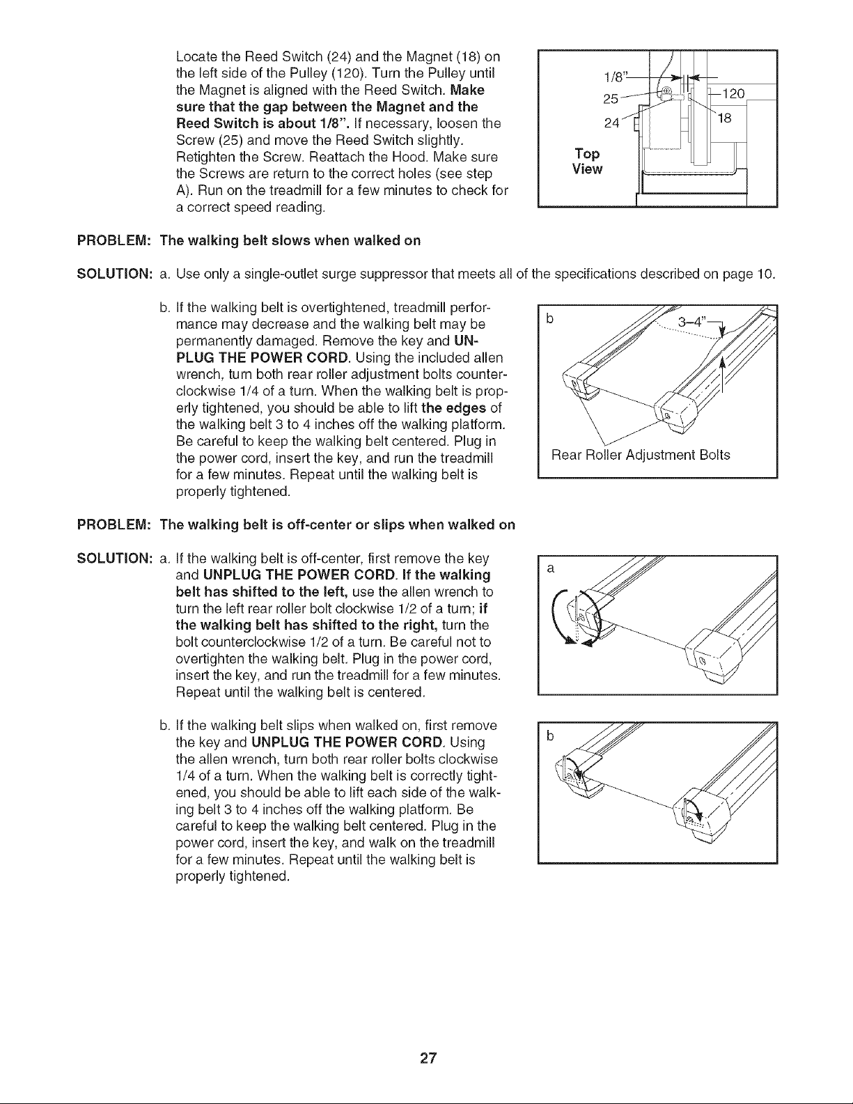
Locate the Reed Switch (24) and the Magnet (18) on
the left side of the Pulley (120). Turn the Pulley until
the Magnet is aligned with the Reed Switch. Make
sure that the gap between the Magnet and the
Reed Switch is about 1/8". If necessary, loosen the
Screw (25) and move the Reed Switch slightly.
Retighten the Screw. Reattach the Hood. Make sure
the Screws are return to the correct holes (see step
A). Run on the treadmill for a few minutes to check for
a correct speed reading.
1/8"-- 7_!. _--
28 ,Ip
PROBLEM: The walking belt slows when walked on
SOLUTION: a. Use only a single-outlet surge suppressor that meets all of the specifications described on page 10.
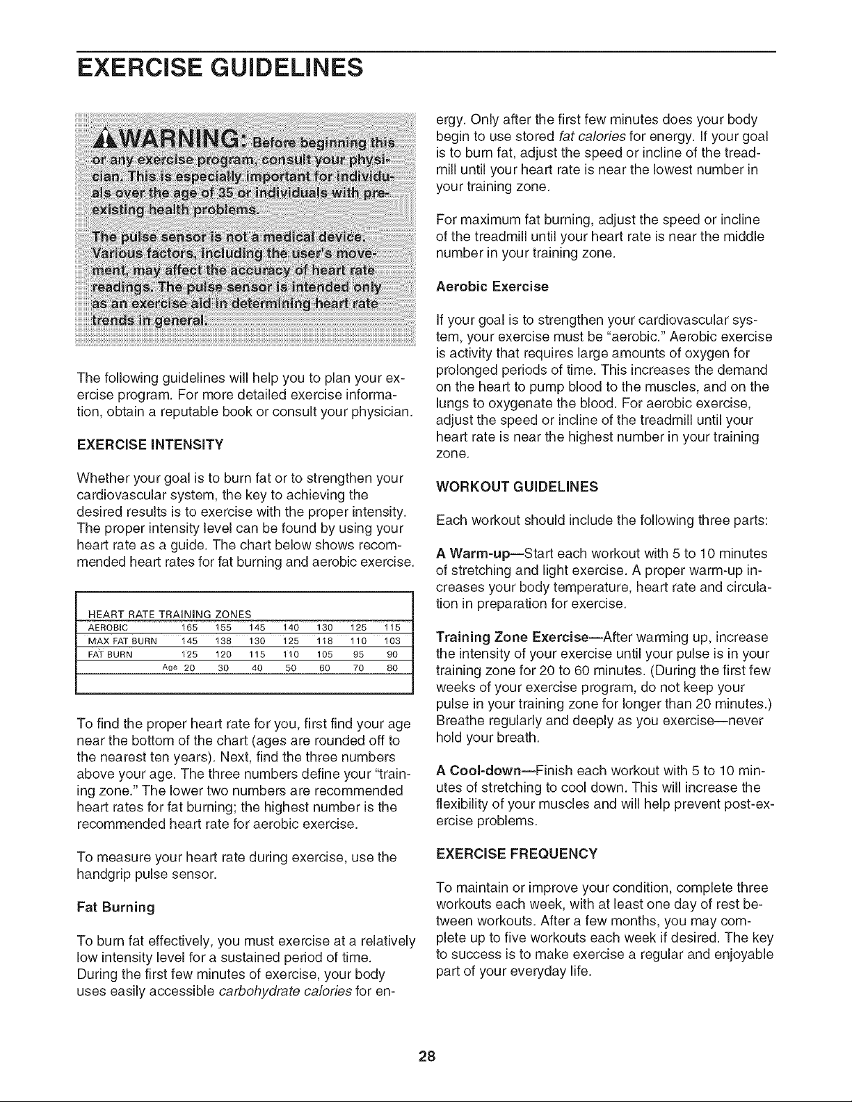
b.
If the walking belt is overtightened, treadmill perfor-
mance may decrease and the walking belt may be
permanently damaged. Remove the key and UN-
PLUG THE POWER CORD. Using the included allen
wrench, turn both rear roller adjustment bolts counter-
clockwise 1/4 of a turn. When the walking belt is prop-
erly tightened, you should be able to lift the edges of
the walking belt 3 to 4 inches off the walking platform.
Be careful to keep the walking belt centered. Plug in
the power cord, insert the key, and run the treadmill
for a few minutes. Repeat until the walking belt is
properly tightened.
Rear Roller Adjustment Bolts
PROBLEM: The walking belt is off-center or slips when walked on
SOLUTION: a.
If the walking belt is off-center, first remove the key
and UNPLUG THE POWER CORD. if the walking
belt has shifted to the left, use the allen wrench to
turn the left rear roller bolt clockwise 1/2 of a turn; if
the walking belt has shifted to the right, turn the
bolt counterclockwise 1/2 of a turn. Be careful not to
overtighten the walking belt. Plug in the power cord,
insert the key, and run the treadmill for a few minutes.
Repeat until the walking belt is centered.
b.
If the walking belt slips when walked on, first remove
the key and UNPLUG THE POWER CORD. Using
the allen wrench, turn both rear roller bolts clockwise
1/4 of a turn. When the walking belt is correctly tight-
ened, you should be able to lift each side of the walk-
ing belt 3 to 4 inches off the walking platform. Be
careful to keep the walking belt centered. Plug in the
power cord, insert the key, and walk on the treadmill
for a few minutes. Repeat until the walking belt is
properly tightened.
27
EXERCISE GUiDELiNES
The following guidelines will help you to plan your ex-
ercise program. For more detailed exercise informa-
tion, obtain a reputable book or consult your physician.
EXERCISE iNTENSiTY
Whether your goal is to burn fat or to strengthen your
cardiovascular system, the key to achieving the
desired results is to exercise with the proper intensity.
The proper intensity level can be found by using your
heart rate as a guide. The chart below shows recom-
mended heart rates for fat burning and aerobic exercise.
HEART RATE TRAINING ZONES
AEROBIC 165 155 145 140 130 125 115
MAX FAT BURN 145 138 130 125 118 110 103
FAT BURN t25 120 115 t10 105 95 90
Age 20 30 40 50 60 70 80
To find the proper heart rate for you, first find your age
near the bottom of the chart (ages are rounded off to
the nearest ten years). Next, find the three numbers
above your age. The three numbers define your "train-
ing zone." The lower two numbers are recommended
heart rates for fat burning; the highest number is the
recommended heart rate for aerobic exercise.
To measure your heart rate during exercise, use the
handgrip pulse sensor.
Fat Burning
To burn fat effectively, you must exercise at a relatively
low intensity level for a sustained period of time.
During the first few minutes of exercise, your body
uses easily accessible carbohydrate calories for en-
ergy. Only after the first few minutes does your body
begin to use stored fat calories for energy. If your goal
is to burn fat, adjust the speed or incline of the tread-
mill until your heart rate is near the lowest number in
your training zone.
For maximum fat burning, adjust the speed or incline
of the treadmill until your heart rate is near the middle
number in your training zone.
Aerobic Exercise
If your goal is to strengthen your cardiovascular sys-
tem, your exercise must be "aerobic." Aerobic exercise
is activity that requires large amounts of oxygen for
prolonged periods of time. This increases the demand
on the heart to pump blood to the muscles, and on the
lungs to oxygenate the blood. For aerobic exercise,
adjust the speed or incline of the treadmill until your
heart rate is near the highest number in your training
zone.
WORKOUT GUIDELINES
Each workout should include the following three parts:
A Warm-up--Start each workout with 5 to 10 minutes
of stretching and light exercise. A proper warm-up in-
creases your body temperature, heart rate and circula-
tion in preparation for exercise.
Training Zone Exercise--After warming up, increase
the intensity of your exercise until your pulse is in your
training zone for 20 to 60 minutes. (During the first few
weeks of your exercise program, do not keep your
pulse in your training zone for longer than 20 minutes.)
Breathe regularly and deeply as you exercise--never
hold your breath.
A Cool-down--Finish each workout with 5 to 10 min-
utes of stretching to cool down. This will increase the
flexibility of your muscles and will help prevent post-ex-
ercise problems.
EXERCISEFREQUENCY
To maintain or improve your condition, complete three
workouts each week, with at least one day of rest be-
tween workouts. After a few months, you may com-
plete up to five workouts each week if desired. The key
to success is to make exercise a regular and enjoyable
part of your everyday life.
28
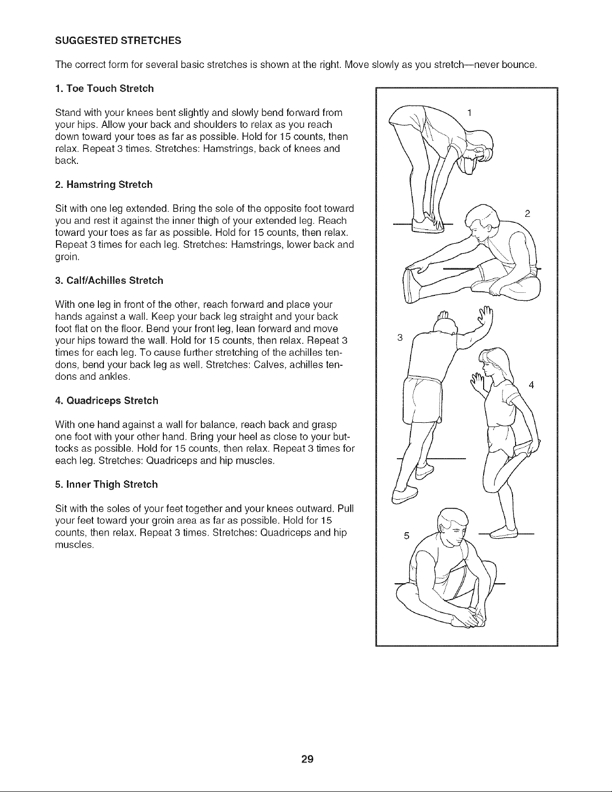
SUGGESTED STRETCHES
The correct form for several basic stretches is shown at the right. Move slowly as you stretch--never bounce.
1. Toe Touch Stretch
Stand with your knees bent slightly and slowly bend forward from
your hips. Allow your back and shoulders to relax as you reach
down toward your toes as far as possible. Hold for 15 counts, then
relax. Repeat 3 times. Stretches: Hamstrings, back of knees and
back.
2. Hamstring Stretch
Sit with one leg extended. Bring the sole of the opposite foot toward
you and rest it against the inner thigh of your extended leg. Reach
toward your toes as far as possible. Hold for 15 counts, then relax.
Repeat 3 times for each leg. Stretches: Hamstrings, lower back and
groin.
3. Calf/Achilles Stretch
With one leg in front of the other, reach forward and place your
hands against a wall. Keep your back leg straight and your back
foot flat on the floor. Bend your front leg, lean forward and move
your hips toward the wall. Hold for 15 counts, then relax. Repeat 3
times for each leg. To cause further stretching of the achilles ten-
dons, bend your back leg as well. Stretches: Calves, achilles ten-
dons and ankles.
4. Quadriceps Stretch
With one hand against a wall for balance, reach back and grasp
one foot with your other hand. Bring your heel as close to your but-
tocks as possible. Hold for 15 counts, then relax. Repeat 3 times for
each leg. Stretches: Quadriceps and hip muscles.
5. Inner Thigh Stretch
Sit with the soles of your feet together and your knees outward. Pull
your feet toward your groin area as far as possible. Hold for 15
counts, then relax. Repeat 3 times. Stretches: Quadriceps and hip
muscles.
29

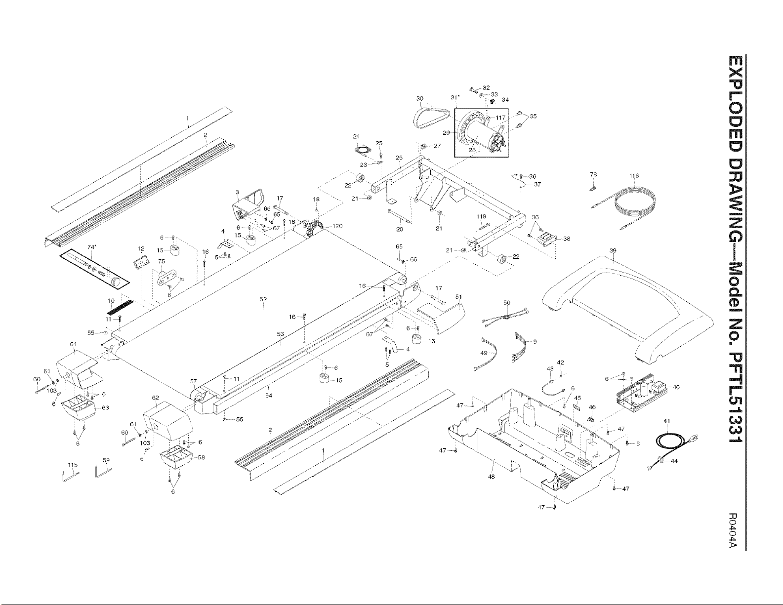
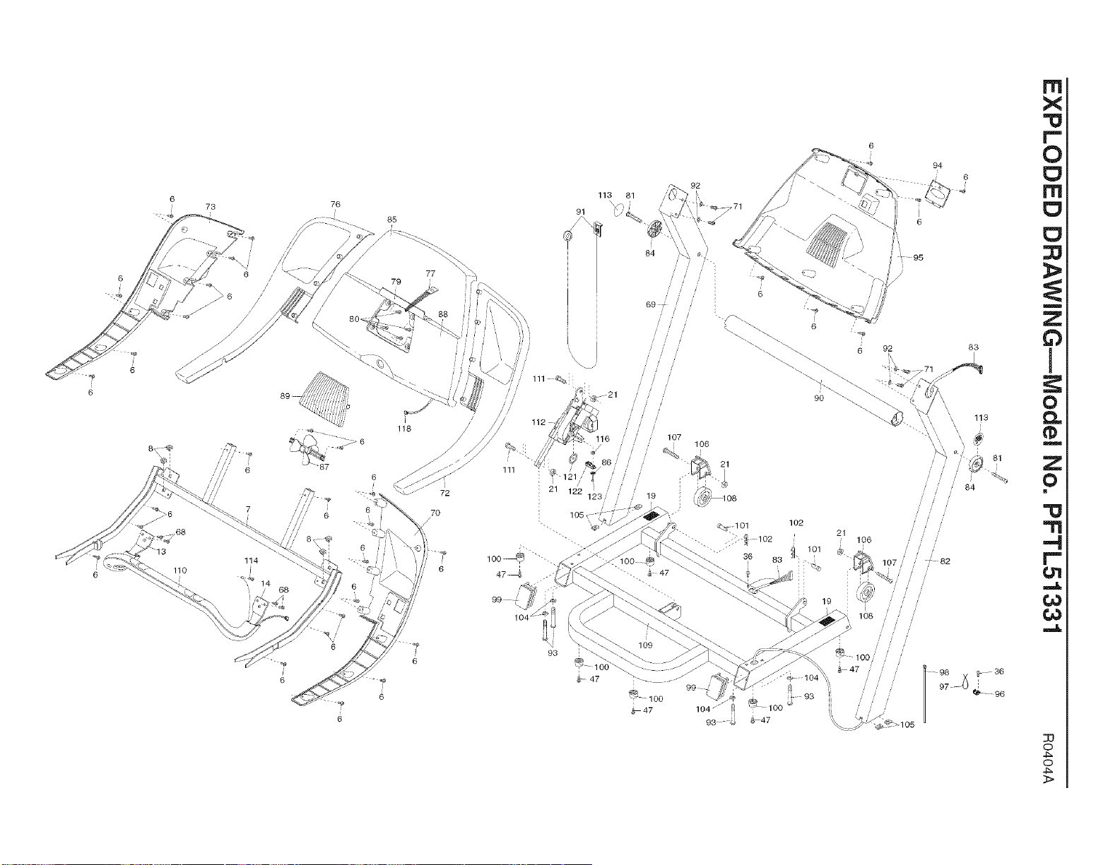
PART LIST--Model No. PFTL51331 RO4O4A
To locate the parts listed below, see the EXPLODED DRAWING attached in the center of this manual.
Key No. Qty. Description Key No. Qty. Description
1 2 Foot Rail Cover 51
2 2 Foot Rail 52
3 1 Left Front Endcap 53
4 2 Belt Guide 54
5 4 Belt Guide Screw 55
6 46 3/4" Screw 56
7 1 Console Frame 57
8 4 Cage Nuts 58
9 1 Incline Wire 59
10 1 Warning Decal 60
11 2 Rear Platform Bolt 61
12 1 Latch Cover 62
13 1 Pulse Bar Plate (Left) 63
14 1 Pulse Bar Plate (Right) 64
15 4 Isolator 65
16 4 Platform Screw 66
17 2 Platform Pivot Bolt 67
18 1 Magnet 68
19 2 Caution Decal 69
20 1 Motor Pivot Bolt 70
21 7 Wheel Nut 71
22 2 Frame Spacer 72
23 1 Reed Switch Clip 73
24 1 Reed Switch 74*
25 1 Reed Switch Screw 75
26 1 Lift Frame 76
27 1 Motor Tension Nut 77
28 1 Motor 78
29 1 Pulley/Flywheel/Fan 79
30 1 Motor Belt 80
31 * 1 Motor Assembly 81
32 1 Motor Tension Bolt 82
33 1 Motor Tension Washer 83
34 1 Motor Star Washer 84
35 2 Motor Bracket Bolt 85
36 7 Small Screw 86
37 2 Ground Wire 87
38 1 Transformer 88
39 1 Hood 89
40 1 Controller 90
41 1 Power Cord 91
42 1 iFIT.com Wire Nut 92
43 1 iFIT.com Wire 93
44 1 Power Cord Grommet 94
45 2 Static Decal 95
46 1 Reset/Off Switch 96
47 11 3/4" Tek Screw 97
48 1 Belly Pan 98
49 1 Photo Switch Wire 99
50 1 Filter Wire 100
1
1
1
1
2
1
1
1
1
2
2
1
1
1
2
2
4
4
1
1
4
1
1
1
1
1
1
1
1
4
2
1
1
2
1
1
1
1
1
1
1
4
4
1
1
1
1
8
2
6
Right Front Endcap
Walking Belt
Walking Platform
Frame
Platform Nut
Right Foot Rail
Rear Roller
Right Rear Foot
Allen Wrench
Rear Roller Adj. Bolt
Rear Roller Washer
Right Rear Endcap
Left Rear Foot
Left Rear Endcap
Small Endcap Screw
Endcap Washer
Front Endcap Screw
Pulse Bar Screw
Left Upright
Right Handgdp (Bottom)
1" Bolt
Right Handgdp (Top)
Left Handgdp (Bottom)
Latch Assembly
Latch Housing
Left Handgdp (Top)
Photo Switch Nut
Jack
Book Holder
Fan Housing Screw
3/8" x 3 1/2" Bolt
Right Upright
Wire Harness
Crossbar Endcap
Console Base
Incline Sensor Washer
Fan
Console
Fan Housing
Crossbar
Key/Clip
1/4" Star Washer
5/16"x 3 1/2" Bolt
Access Door
Console Back
Tie Holder
Releasable Tie
Plastic Tie
Base Endcap
Base Pad
3O

Key No. Qty.
101 2
102 2
103 2
104 4
105 4
106 2
107 2
108 2
109 1
110 1
111 2
112 1
113 1
114 1
115 1
116 1
117 1
Description
Clevis Pin
Hairpin Cotter
Rear Roller Star Washer
5/16" Star Washer
U-Nut
Wheel Housing
Wheel Bolt
Wheel
Base
Pulse Bar
Incline Motor Bolt
Incline Motor
Cap Decal
1/2" Ground Screw
5/16" Allen Wrench
iFit.com Cable
Motor Bracket
Key No. Qty. Description
118 1 Pulse Wire
119 1 Front Roller Adj. Bolt
120 1 Front Roller/Pulley
121 1 Optic Disk
122 1 Photo Switch
123 1 Photo Switch Wire
# 1 4" Blue Wire, 2 F
# 1 4" Blue Wire, M/F
# 1 4" Black Wire, M/F
# 1 4" Red Wire, M/F
# 1 12" Green Wire, F/Ring
# 1 User's Manual
* Includes all parts shown in the box
# These parts are not illustrated
Specifications are subject to change without notice.
31
6O
74*
10
1
2
57
I
55
52
53
30 31 *
21
16
20
65
_: 66
j
21
_ 32
33
235
36
47
116
41
I
r'ri
X
i--
0
rTi
m
Z
0
!
0
m
Z
0
m
-4
i-
¢,n
t_
¢o
23
0
0
11o
76
j_
/
6
85
118
6
/ /
/
47 4
99
©
111 {_.
112
'7 121
21 122
113 81
9"
84
69 _
21
116 107
%,
19
47
109
93
10(
106
_9
6 92
6
95
102
<_ 101
2"
102 106
_] 101
36 83
_. -
19
IO8
_ 93
1O0
1O0
_47
94
6
83
113
,_ 82
96
r'ri
X
0
rTi
::8
m
Z
0
!
0
m
Z
0
m
"!1
.-4
¢,n
0_
¢o
33
0
0

HOW TO ORDER REPLACEMENT PARTS
To order replacement parts, call our Customer Service Department toll-free at 1-888-533-1333, Monday through
Friday, 6 a.m. until 6 p.m. Mountain Time (excluding holidays). To help us assist you, please be prepared to give
the following information:
The MODEL NUMBER of the product (PFTL51331)
The NAME of the product (PROFORM _>530i treadmill)
The SERIAL NUMBER of the product (see the front cover of this manual)
The KEY NUMBER and DESCRIPTION of the part(s) (see the PART LIST on pages 30 and 31)
LIMITED WARRANTY
ICON Health & Fitness, Inc. dCON), warrants this product to be free from defects in workmanship and
material, under normal use and service conditions, for a period of ninety (90) days from the date of pur-
chase. This warranty extends only to the original purchaser. ICON's obligation under this warranty is lim-
ited to replacing or repairing, at ICON's option, the product through one of its authorized service centers.
All repairs for which warranty claims are made must be pre-authorized by ICON. This warranty does not
extend to any product or damage to a product caused by or attributable to freight damage, abuse, mis-
use, improper or abnormal usage or repairs not provided by an ICON authorized service center; prod-
ucts used for commercial or rental purposes; or products used as store display models. No other war-
ranty beyond that specifically set forth above is authorized by ICON.
ICON is not responsible or liable for indirect, special or consequential damages arising out of or in con-
nection with the use or performance of the product or damages with respect to any economic loss, loss
of property, loss of revenues or profits, loss of enjoyment or use, costs of removal or installation or other
consequential damages of whatsoever nature. Some states do not allow the exclusion or limitation of in-
cidental or consequential damages. Accordingly, the above limitation may not apply to you.
The warranty extended hereunder is in lieu of any and all other warranties and any implied warranties of
merchantability or fitness for a particular purpose is limited in its scope and duration to the terms set
forth herein. Some states do not allow limitations on how long an implied warranty lasts. Accordingly, the
above limitation may not apply to you.
This warranty gives you specific legal rights. You may also have other rights which vary from state to state.
iCON HEALTH & FITNESS, iNC., 1500 S. 1000 W., LOGAN, UT 84321-9813
Part No. 207574 RO404A Printed in USA © 2004 ICON IP, Inc.