Loading ...
Loading ...
Loading ...
SiUS121827E Wiring Error Check Function
Part 7 Trial Operation and Field Settings 249
3. Wiring Error Check Function
Outline Wiring error check function is designed for the microcomputer to correct wiring errors itself.
If local wiring is unclear in the case of buried piping, for example, just press the wiring error check
switch on the outdoor unit. Even if the connections for Room A and Room B are confused, the
system may run without a hassle.
Note that this check function does not work in the following cases.
For 3-minute standby period after the power is turned on or after the compressor has stopped.
When the outdoor temperature is below 5°C (41°F).
If the indoor unit is in trouble (also in case of all-room transmission failure).
When the piping and wiring are perfect, there is no need to use this function.
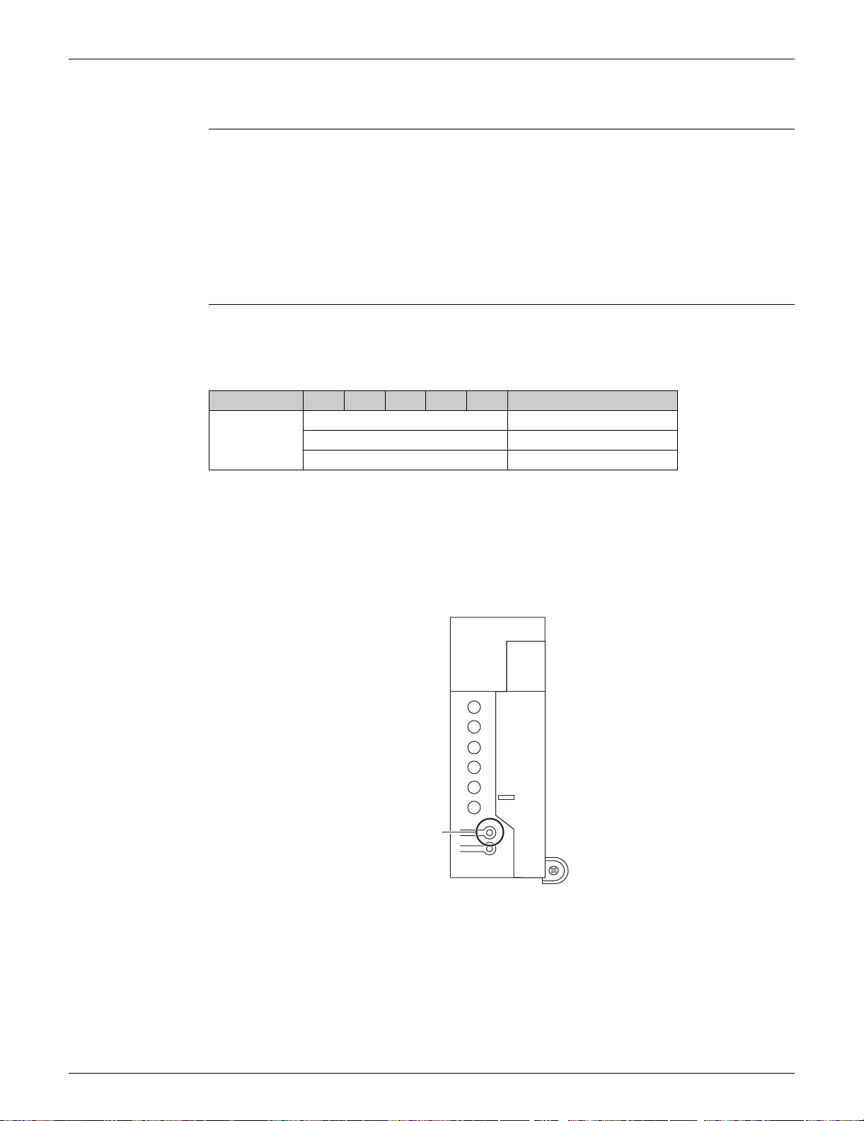
Procedure 1. Press the wiring error check switch (SW3) on the service monitor PCB of the outdoor unit, and
the wiring error check function is activated.
2. In about 15 ~ 25 minutes, the check finishes automatically.
3. When the check is over, the service monitor LED indicators start blinking.
Self-correction complete…The LED indicators 1 - 5 blink one after another.
Self-correction impossible…The LED indicators blink all at the same time.
Transmission failure occurs at any of the indoor units.
The indoor unit heat exchanger thermistor is disconnected.
An indoor unit is in trouble (if a trouble occurs during the wiring error checking).
Emergency stop…If any of the LED indicators stays on, follow the diagnostic procedure.
LED 1 2 3 4 5 Judgment
Status
Blinking one after another Self-correction completed
All blinking Self-correction impossible
Any of the LEDs stay on Emergency stop
Service monitor PCB
(R22003)
A
1
2
3
4
5
Wiring error
check switch
(SW3)
Loading ...
Loading ...
Loading ...