Loading ...
Loading ...
Loading ...
Check SiUS121827E
238 Part 6 Service Diagnosis
8.8 Inverter Analyzer Check
Check No.15 Characteristics
Inverter analyzer: RSUK0917C
If an abnormal stop occurs due to compressor startup failure or overcurrent output when using an
inverter unit, it is difficult to judge whether the stop is caused by the compressor failure or some
other failure (main PCB, power module, etc.). The inverter analyzer makes it possible to judge the
cause of trouble easily and securely. Connect an inverter analyzer as a quasi-compressor instead
of compressor and check the output of the inverter.
Operation Method
Step 1
Be sure to turn the power off.
Step 2
Install an inverter analyzer instead of a compressor.
Note:
Make sure the charged voltage of the built-in smoothing electrolytic capacitor drops to 10 VDC or
below before carrying out the service work.
Reference:
If the terminals of the compressor are not FASTON terminals (difficult to remove the wire on the
terminals), it is possible to connect wires available on site to the outdoor unit from output side of
PCB. Do not connect them to the compressor at the same time, otherwise it may result in incorrect
detection.
Step 3
Activate the power transistor test operation from the outdoor unit.
Press the forced cooling operation ON/OFF switch for 5 seconds.
(Refer to page 248 for the position.)
→ Power transistor test operation starts.
Diagnose method (Diagnose according to 6 LEDs lighting status.)
(
R22731
)
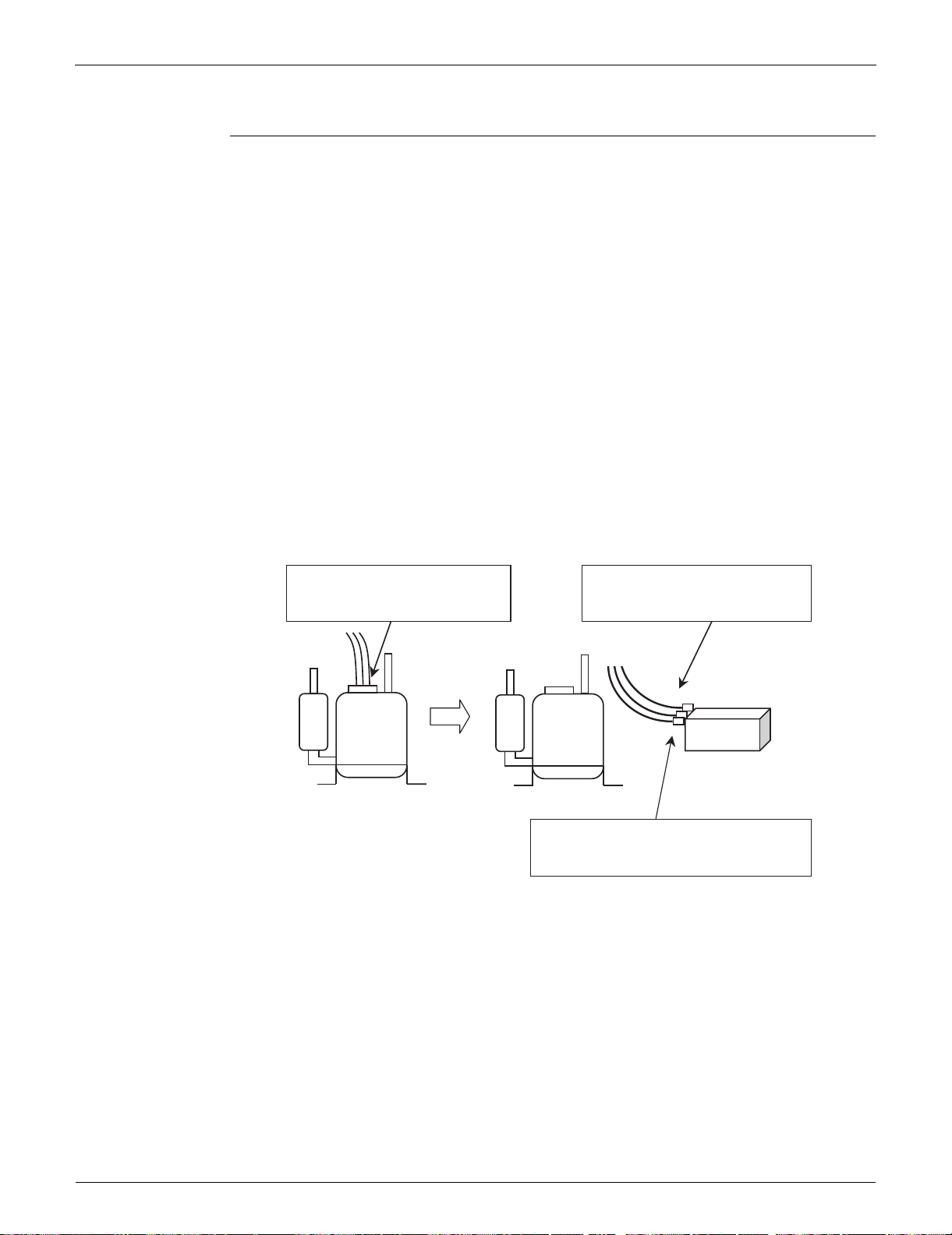
(1) Remove the terminals from
the compressor.
(2) Connect the terminals to the
terminals of the inverter
analyzer.
Compressor
Inverter analyzer
Be careful not to let the terminals (U,V,W)
touch each other. Otherwise, high voltage
is applied.
Compressor
Loading ...
Loading ...
Loading ...