Loading ...
Loading ...
Loading ...
SiUS121827E Check
Part 6 Service Diagnosis 233
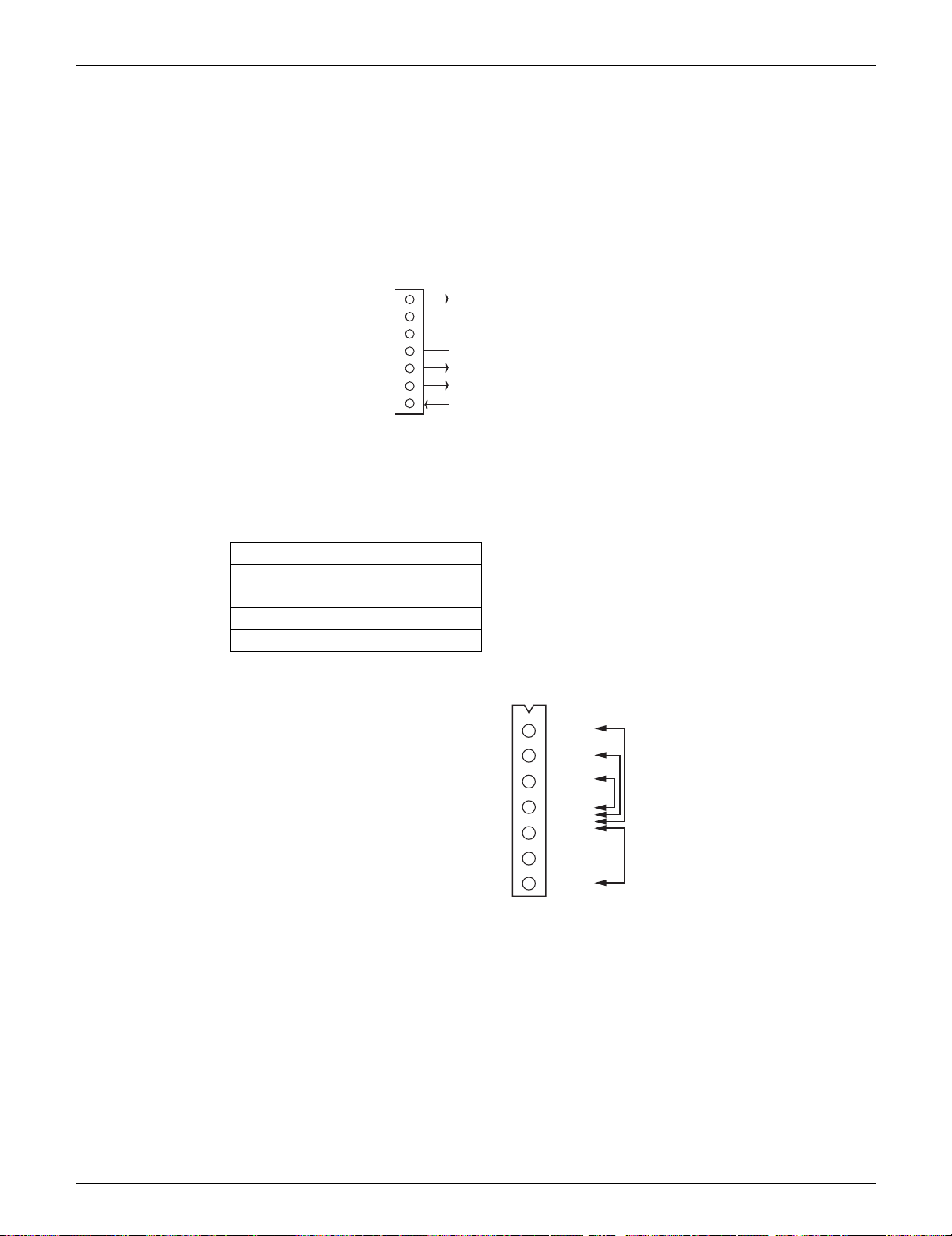
8.2 Indoor Fan Motor Connector Check
Check No.02 FTXR, CTXG, CTXS, FTXS, FVXS Series
1. Check the connection of connector.
2. Check motor power supply voltage output (pins 4 - 7).
3. Check motor control voltage (pins 4 - 3).
4. Check rotation command voltage output (pins 4 - 2).
5. Check rotation pulse input (pins 4 - 1).
FDMQ Series
1. Turn the power supply OFF.
2. With the fan motor connector disconnected, measure the resistance between each pin, then
make sure that the resistance is more than the value mentioned in the following table.
Measuring points Judgement
White - Blue 1 MΩ or more
Orange - Blue 100 kΩ or more
Brown - Blue 100 Ω or more
Red - Blue 100 kΩ or more
7
6
5
4
3
2
1
S1 or S200
(R14225)
Motor power supply voltage (310 ~ 340 VDC)
Unused
Unused
GND
Motor control voltage (15 VDC)
Rotation command voltage (1~ 5 VDC)
Rotation pulse input
White
Orange
Brown
Blue
—
—
Red
FG
Vsp
Vcc
GND
—
—
Vdc/Vm
X8A
(R25080)
Loading ...
Loading ...
Loading ...