Loading ...
Loading ...
Loading ...
W415-1343 / A / 11.18.16
5
EN
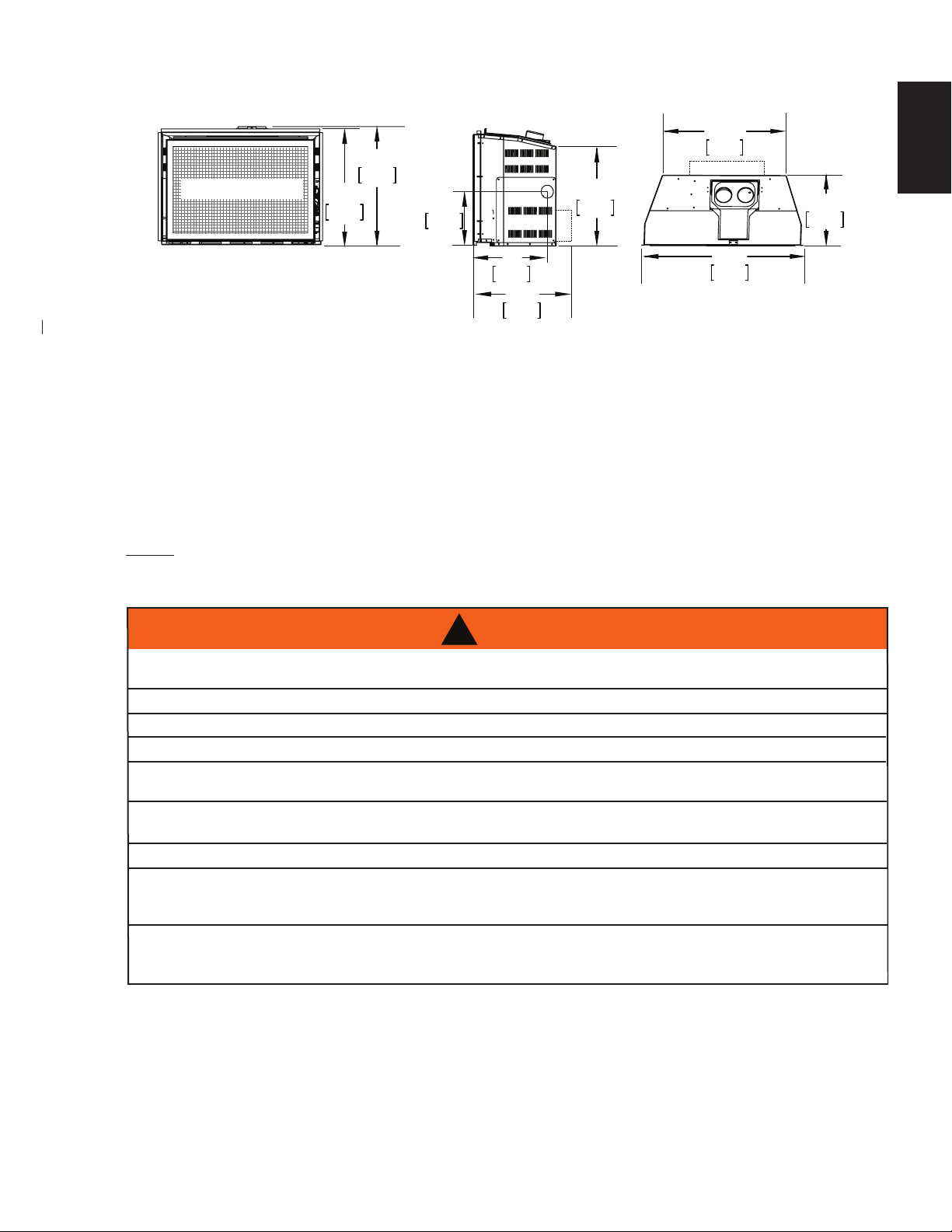
2.1 DIMENSIONS
THIS GAS APPLIANCE SHOULD BE INSTALLED AND SERVICED BY A QUALIFIED INSTALLER
to
conform with local codes. Installation practices vary from region to region and it is important to know the
specifi cs that apply to your area, for example in Massachusetts State:
• This product must be installed by a licensed plumber or gas fi tter when installed within the commonwealth
of Massachusetts.
• The appliance damper must be removed or welded in the open position prior to installation of an appliance
insert or gas log.
•
The appliance off valve must be a “T” handle gas cock.
•
The fl exible connector must not be longer than 36 inches (91.4cm).
• A Carbon Monoxide detector is required in all rooms containing gas fi red appliances.
• The appliance is not approved for installation in a bedroom or bathroom unless the unit is a direct vent
sealed combustion product.
The installation must conform with local codes or, in
absence of local codes, the National Gas and Propane
Installation Code CSA B149.1 in Canada, or the National
Fuel Gas Code, ANSI Z223.1 / NFPA 54 in the United
States. Suitable for mobile home installation if installed in
accordance with the current standard CAN/CSA Z240MH
Series, for gas equipped mobile homes, in Canada or
ANSI Z223.1 and NFPA 54 in the United States.
Some appliances have optional fans or blowers. If an optional fan or blower is installed, the junction box must
be electrically connected and grounded in accordance with local codes, use the current CSA C22.1 Canadian
Electrical Code in Canada or the ANSI/NFPA 70 National Electrical code in the United States.
ALWAYS LIGHT THE PILOT WHETHER FOR THE FIRST TIME OR IF THE GAS SUPPLY HAS RUN OUT,
WITH THE GLASS DOOR OPENED OR REMOVED.
PROVIDE ADEQUATE CLEARANCE FOR SERVICING AND OPERATING THE APPLIANCE.
PROVIDE ADEQUATE VENTILATION.
NEVER OBSTRUCT THE FRONT OPENING OF THE APPLIANCE.
OBJECTS PLACED IN FRONT OF THE APPLIANCE MUST BE KEPT A MINIMUM OF 48 INCHES
(121.9cm) FROM THE FRONT FACE OF THE APPLIANCE.
SURFACES AROUND AND ESPECIALLY ABOVE THE APPLIANCE CAN BECOME HOT. AVOID CONTACT
WHEN THE APPLIANCE IS OPERATING.
FIRE RISK. EXPLOSION HAZARD.
HIGH PRESSURE WILL DAMAGE VALVE. DISCONNECT GAS SUPPLY PIPING BEFORE PRESSURE TESTING GAS
LINE AT TEST PRESSURES ABOVE 1/2 PSIG. CLOSE THE MANUAL SHUT-OFF VALVE BEFORE PRESSURE
TESTING GAS LINE AT TEST PRESSURES EQUAL TO OR LESS THAN 1/2 PSIG (35mb).
USE ONLY WOLF STEEL APPROVED OPTIONAL ACCESSORIES AND REPLACEMENT PARTS WITH THIS APPLIANCE.
USING NON-LISTED ACCESSORIES (BLOWERS, DOORS, LOUVRES, TRIMS, GAS COMPONENTS, VENTING
COMPONENTS, ETC.) COULD RESULT IN A SAFETY HAZARD AND WILL VOID THE WARRANTY AND CERTIFICATION.
THE APPLIANCE MUST NOT BE OPERATED AT TEMPERATURES BELOW FREEZING (32°F / 0°C).
!
WARNING
This appliance must be recessed into a vented noncombustible wood-burning appliance (prefabricated or
masonry) only. The minimum appliance opening size in which the appliance is to be installed is:
HEIGHT 21
1
/
2
" (54.6cm) WIDTH 29" (73.7cm) DEPTH *13
1
/
2
" (34.3cm)
The minimum allowable chimney flue size is 7" (177.8mm) round.
*Add 4" (102mm) for optional blower.
The minimum distance, from the bottom of a combustible mantel projecting 3" (76mm) maximum from the
wall to the top of the appliance, is 14" (35.6cm) (See MINIMUM MANTEL CLEARANCES section).
NOTE: A NON-COMBUSTIBLE HEARTH MUST PROTRUDE A MINIMUM OF 12" (30.5cm) FROM THE
APPLIANCE.
2.2 MINIMUM CLEARANCE TO COMBUSTIBLES
21"
533mm
20 1/2"
521mm
12"
305mm
17 1/2"
445mm
9 1/2"
241mm
17 1/2"
445mm
29 5/8"
753mm
22 7/8"
581mm
13 1/4"
337mm
SAFETY BARRIER
2.3 GENERAL INSTRUCTIONS
*
*REQUIRED DIMENSION WITH THE OPTIONAL BLOWER KIT INSTALLED.
Loading ...
Loading ...
Loading ...