#61-521
Phase/Motor Rotation Tester
Instruction Manual
61-521 Features:
• Phase rotation
• Motor rotation
• Low battery indicator
• Cat III 600V
Read First: Safety Information
Understand and follow operating instructions carefully. Use the tester only as
specied in this manual; otherwise, the protection provided by the tester may
be impaired.
WARNING
To avoid possible electric shock, personal injury or death, follow these guidelines:
• Do not use if tester appears damaged. Visually inspect the tester to ensure case is not cracked and back case is
securely in place.
• Inspect and replace leads if insulation is damaged, metal is exposed, or probes are cracked. Pay particular
attention to the insulation surrounding the connectors.
• Do not use tester if it operates abnormally as protection maybe impaired.
• Do not use during electrical storms or in wet weather.
• Do not use around explosive gas, dust, or vapor.
• Do not apply more than the rated voltage to the tester.
• Do not use without the battery and the back case properly installed.
• Replace battery as soon as the low battery indicator “ OK” LED unlights to avoid false readings.
• Remove the test leads from the circuit prior to removing battery cap.
• Do not attempt to repair this unit as it has no user-serviceable parts.
• If in doubt, check the fuses using an ohmmeter.
Important Note: There will be no indication of voltage or phasing if the tester’s fuses are blown. Always verify
tester operation on a known live circuit.
CAUTION
To protect yourself, think “Safety First”:
• Voltages exceeding 30VAC or 60VDC pose a shock hazard so use caution.
• Use appropriate personal protective equipment such as safety glasses, face shields, insulating gloves, insulating
boots, and/or insulating mats.
• Use the proper terminals for your measurements.
• Never ground yourself when taking electrical measurements.
• Always work with a partner.
• When using the probes, keep ngers as far behind the probe tips as possible.
OPERATING INSTRUCTIONS:
Determination of the rotary field direction and phase presence:
On a 3 Phase System, the sequence of the 3 phases determines the rotation of a 3 phase motor connected to that
system. The correct 3 phase sequence results in a clockwise rotation of a connected motor.
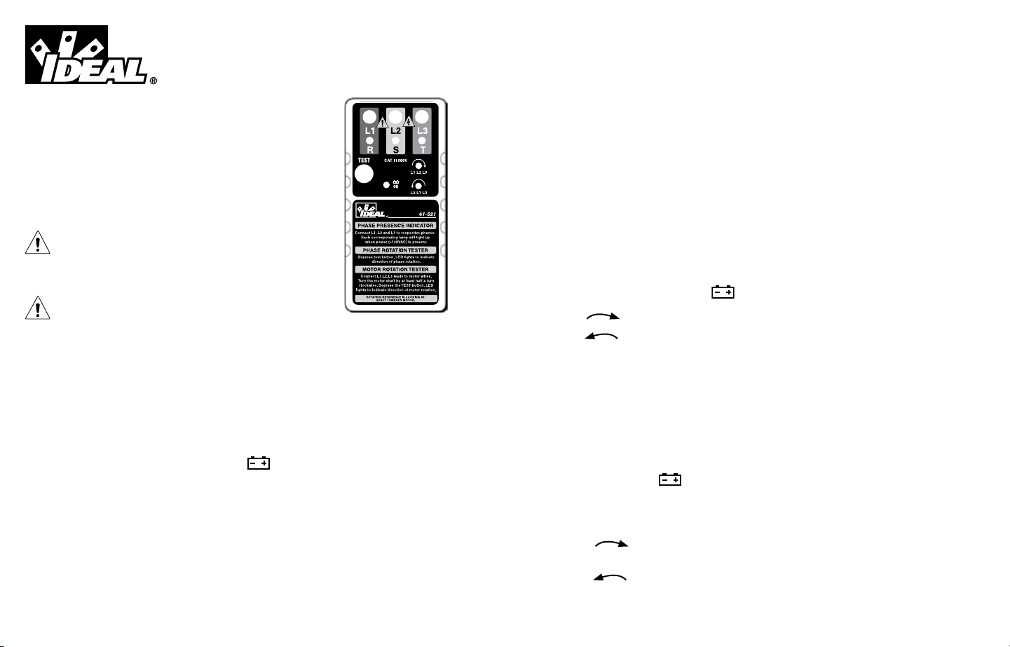
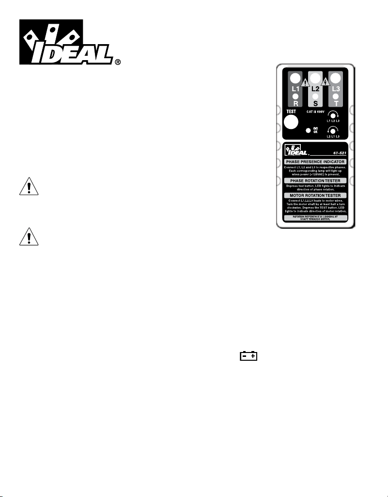
• Insert the test leads to the matching color coded sockets of the instrument. Red to R, White (or yellow) to S,
Blue (or black) to T.
• Clip the test probes to the three phases (R,S,T). When connecting to a voltage greater than 100VAC,
the corresponding neon lamp will start to glow, indicating the presence of the voltage on its corresponding lead
(R,S,T lamps).
• Press the TEST button to turn the instrument “ON”. The green LED indicates that the instrument is ON and is
testing. The battery is OK when the green “ OK” LED is ON. Should the Green LED not come on while
depressing the TEST button, replace the battery (see Battery Replacement).
If the LED L1-L2-L3 is illuminated, a clockwise rotary eld is present.
If the LED L2-L1-L3 is illuminated, a counter clockwise rotary eld is present.
Please note that the phase voltage is indicated even if the neutral conductor N is connected in place of a
phase conductor.
Determination of motor connections and motor rotation:
• Insert the test leads into the instrument using the color codes then to the motor wiring per the chart below.
Test Lead Tester Input Motor Wiring
Red R/L1 L1
White (or yellow) S/L2 L2
Blue (or black) T/L3 L3
• Press the button. The green “ OK” LED indicates that the instrument is ready for testing.
Turn the motor shaft by at least a half rotation clockwise. Look at the LED’s while the shaft is spinning.
Note: A relatively low RPM is sufcient to perform the measurement.
It is important to ensure that the user faces the drive shaft, looking toward the motor and the front side of the
tester at the same time, so that motor rotation can be conrmed.
The red LED L1-L2-L3 indicates clockwise motor rotation if the leads are properly connected as follows: L1 to R,
L2 to S, and L3 to T.
The red LED L2-L1-L3 indicates counter- clockwise motor rotation if the leads are improperly connected, such as
L1 to R, L2 to S, and L3 to T. Switch the red and white test lead connections and conrm the proper clockwise
rotation now exists.
2

#61-521
Phase/Motor Rotation Tester
Instruction Manual
61-521 Features:
• Phase rotation
• Motor rotation
• Low battery indicator
• Cat III 600V
Read First: Safety Information
Understand and follow operating instructions carefully. Use the tester only as
specied in this manual; otherwise, the protection provided by the tester may
be impaired.
WARNING
To avoid possible electric shock, personal injury or death, follow these guidelines:
• Do not use if tester appears damaged. Visually inspect the tester to ensure case is not cracked and back case is
securely in place.
• Inspect and replace leads if insulation is damaged, metal is exposed, or probes are cracked. Pay particular
attention to the insulation surrounding the connectors.
• Do not use tester if it operates abnormally as protection maybe impaired.
• Do not use during electrical storms or in wet weather.
• Do not use around explosive gas, dust, or vapor.
• Do not apply more than the rated voltage to the tester.
• Do not use without the battery and the back case properly installed.
• Replace battery as soon as the low battery indicator “ OK” LED unlights to avoid false readings.
• Remove the test leads from the circuit prior to removing battery cap.
• Do not attempt to repair this unit as it has no user-serviceable parts.
• If in doubt, check the fuses using an ohmmeter.
Important Note: There will be no indication of voltage or phasing if the tester’s fuses are blown. Always verify
tester operation on a known live circuit.
CAUTION
To protect yourself, think “Safety First”:
• Voltages exceeding 30VAC or 60VDC pose a shock hazard so use caution.
• Use appropriate personal protective equipment such as safety glasses, face shields, insulating gloves, insulating
boots, and/or insulating mats.
• Use the proper terminals for your measurements.
• Never ground yourself when taking electrical measurements.
• Always work with a partner.
• When using the probes, keep ngers as far behind the probe tips as possible.
OPERATING INSTRUCTIONS:
Determination of the rotary field direction and phase presence:
On a 3 Phase System, the sequence of the 3 phases determines the rotation of a 3 phase motor connected to that
system. The correct 3 phase sequence results in a clockwise rotation of a connected motor.
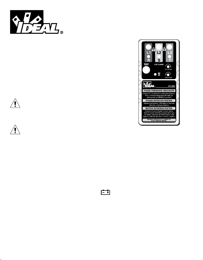
• Insert the test leads to the matching color coded sockets of the instrument. Red to R, White (or yellow) to S,
Blue (or black) to T.
• Clip the test probes to the three phases (R,S,T). When connecting to a voltage greater than 100VAC,
the corresponding neon lamp will start to glow, indicating the presence of the voltage on its corresponding lead
(R,S,T lamps).
• Press the TEST button to turn the instrument “ON”. The green LED indicates that the instrument is ON and is
testing. The battery is OK when the green “ OK” LED is ON. Should the Green LED not come on while
depressing the TEST button, replace the battery (see Battery Replacement).
If the LED L1-L2-L3 is illuminated, a clockwise rotary eld is present.
If the LED L2-L1-L3 is illuminated, a counter clockwise rotary eld is present.
Please note that the phase voltage is indicated even if the neutral conductor N is connected in place of a
phase conductor.
Determination of motor connections and motor rotation:
• Insert the test leads into the instrument using the color codes then to the motor wiring per the chart below.
Test Lead Tester Input Motor Wiring
Red R/L1 L1
White (or yellow) S/L2 L2
Blue (or black) T/L3 L3
• Press the button. The green “ OK” LED indicates that the instrument is ready for testing.
Turn the motor shaft by at least a half rotation clockwise. Look at the LED’s while the shaft is spinning.
Note: A relatively low RPM is sufcient to perform the measurement.
It is important to ensure that the user faces the drive shaft, looking toward the motor and the front side of the
tester at the same time, so that motor rotation can be conrmed.
The red LED L1-L2-L3 indicates clockwise motor rotation if the leads are properly connected as follows: L1 to R,
L2 to S, and L3 to T.
The red LED L2-L1-L3 indicates counter- clockwise motor rotation if the leads are improperly connected, such as
L1 to R, L2 to S, and L3 to T. Switch the red and white test lead connections and conrm the proper clockwise
rotation now exists.
2

N12966
Battery Replacement:
• Ensure test leads are disconnected from circuit or components.
• Remove test leads from input jacks on tester.
• Remove the two screws from the back case.
• Remove the back case.
• Replace battery with a new 9V battery.
• Assemble the back case to the tester and re-tighten the screws.
Fuse Replacement:
Unscrew the back cover, replace fuse(s) with the same type fuse (5 x 20mm, 200mA/250V). Screw the cover back
into place.
Maintenance:
Clean the case with a damp cloth and mild detergent. Do not use abrasives or solvents.
Service and Replacement Parts:
This unit has no user-serviceable parts.
For replacement parts or to inquire about service information contact IDEAL INDUSTRIES, INC at (877)-201-9005 or
visit our website www.testersandmeters.com.
SPECIFICATIONS:
Nominal Voltage for Phase Presence Indication: 100 - 600VAC (10-400Hz)
Phase Rotary Field Direction: 1– 600VAC (2-400Hz)
Determination of Motor Rotation (requires > ½ turn): 1-600VAC (2-400Hz)
Over Load Protection: 550V (between all terminals)
Fuses: 5 x 20mm, 200mA/ 250V fuse
Low Battery Indicator: The “ OK” LED unlights when battery voltage
drops below operating level.
Battery: (1) 9V, IEC 6LR61
Current Consumption: Max 18 mA.
Size: 6.0”Hx2.8”Wx1.4”D (151mmHx72mmW x 35 mmD)
Weight: 6.4oz (181g) including battery
Display: Neon Lamps and LEDs
Accessories included: Carrying Case, Alligator Clip Leads, (1) 9V battery,
operating instructions.
Operating Temperature Range: 5ºF to 131ºF (-15°C to + 55°C)
Storage Temperature: -4ºF to 158ºF (-20°C to + 70°C)
Safety: Cat III – 600V
Double Insulation
Instrument has been evaluated and complies with insulation category III (overvoltage category III). Pollution degree
2 in accordance with IEC-644. Indoor use.
Dispose of waste electrical and electronic equipment
In order to preserve, protect and improve the quality of environment, protect human health
and utilize natural resources prudently and rationally, the user should return unserviceable
product to relevant facilities in accordance with statutory regulations. The crossed-out
wheeled bin indicates the product needs to be disposed separately and not as municipal waste.
Disposal of used batteries/accumulators!
The user is legally obliged to return used batteries and accumulators. Disposing used batteries in the household waste
is prohibited! Batteries/accumulators containing hazardous substances are marked with the crossed-out wheeled bin.
The symbol indicates that the products forbidden to be disposed via the domestic refuse. The chemical symbols for the
respective hazardous substances are Cd = Cadmium, Hg = Mercury, Pb = Lead. You can return used batteries/
accumulators free of charge to any collecting point of your local authority, our stores, or where batteries/accumulators
are sold. Consequently you comply with your legal obligations and contribute to environmental protection.
Warranty Statement:
This tester is warranted to the original purchaser against defects in material and workmanship for two years from
the date of purchase. During this warranty period, IDEAL INDUSTRIES, INC. will, at its option, replace or repair the
defective unit, subject to verication of the defect or malfunction. This warranty does not cover fuses, batteries or
damage from abuse, neglect, accident, unauthorized repair, alteration, or unreasonable use of the instrument.
Any implied warranties arising out of the sale of an IDEAL product, including but not limited to implied warranties of
merchantability and tness for a particular purpose, are limited to the above. The manufacturer shall not be liable for
loss of use of the instrument or other incidental or consequential damages, expenses, or economic loss, or for any
claim or claims for such damage, expenses or economic loss.
State laws vary, so the above limitations or exclusions may not apply to you. This warranty gives you specic legal
rights, and you may also have other rights which vary from state to state.
3 4
#61-521
Probador de rotación de fases/
motores
Manual de Instrucciones
Funciones del 61-521:
• Rotación de fases
• Rotación de motores
• Indicador de batería con poca carga
• Cat III 600V
Lea primeramente: Información de seguridad
Asegúrese de entender y seguir cuidadosamente las instrucciones de operación.
Use el instrumento sólo como se especica en este manual. De lo contrario, la
protección que proporciona el mismo puede reducirse.
ADVERTENCIA
Para evitar posibles riesgos de electrocución, lesiones o la muerte, siga estas pautas:
• No use el instrumento si el mismo parece estar dañado. Inspecciónelo visualmente para asegurarse de que la
cubierta no esté surada y que la parte trasera de la misma esté rmemente colocada en su sitio.
• Inspeccione y reemplace los cables si el aislamiento está dañado, hay piezas metálicas expuestas o las sondas
están suradas. Preste particular atención al aislamiento de alrededor de los conectores.
• No use el instrumento si funciona en forma anormal, porque puede verse reducida la protección.
• No use el instrumento durante tormentas eléctricas o con tiempo húmedo.
• No use el instrumento cerca de gases explosivos, polvo o vapor.
• No aplique al instrumento voltajes superiores al nominal.
• No use el instrumento sin las baterías ni si la parte posterior de la cubierta no está instalada correctamente.
• Reemplace la batería tan pronto se enciende el indicador de la misma , a n de evitar lecturas falsas.
• Retire los cables de prueba del circuito antes de desmontar la tapa de las baterías.
• No intente reparar esta unidad puesto que no tiene piezas reparables por el usuario.
• Si tiene dudas, verique los fusibles con un óhmetro.
Nota importante: No hay indicación de voltaje ni de secuencia de fases si los fusibles están quemados. Comprue-
be siempre la presencia de voltaje con un instrumento apropiado o en un circuito que se sabe que está alimentado.
PRECAUCIÓN
Para protegerse, piense que “¡La seguridad primero!”:
• Los voltajes superiores a 30 VCA o 60 VCC representan un riesgo de electrocución, por lo que debe trabajar
con precaución.
• Use equipos de protección personal apropiados, tales como gafas de seguridad, máscaras faciales, guantes,
calzado y/o alfombras aislantes.
• Use los terminales apropiados para sus medidas.
• No se conecte a tierra cuando tome medidas eléctricas.
• Trabaje siempre con un compañero.
• Cuando use las sondas, mantenga los dedos tan lejos de las puntas de las mismas como sea posible.
INSTRUCCIONES DE OPERACIÓN:
Determinación del sentido y la secuencia de fases del campo rotativo:
En un sistema trifásico, la secuencia de las 3 fases determina la rotación del motor trifásico conectado a ese
sistema. La secuencia correcta de las 3 fases produce la rotación del motor conectado en sentido horario.
• Inserte los cables de prueba en los zócalos del instrumento con código de color coincidente. Rojo al R, blanco
(o amarillo) al S, azul (o negro) al T.
• Prenda las sondas de prueba a las tres fases (R, S y T). Cuando se conecta a un generador de voltaje de más de
100 VCA, la lámpara de neón correspondiente comienza a iluminarse, para indicar la presencia del voltaje en su
cable correspondiente (lámparas de R, S y T).
• Pulse el botón TEST para encender el instrumento. El LED verde indica que el instrumento está encendido y en
prueba. La batería está en buen estado cuando el LED verde está encendido. En caso de que el LED verde no se
encienda cuando se presiona el botón TEST, reemplace la batería (consulte Reemplazo de la batería).
Si se enciende el LED L1-L2-L3, indica la presencia de un campo rotativo en sentido horario.
Si se enciende el LED L2-L1-L3, indica la presencia de un campo rotativo en sentido antihorario.
Tenga en cuenta que se indica el voltaje de fase incluso si el conductor neutro N se conecta en lugar del
conductor de un fase.
Determinación de las conexiones y la rotación del motor:
• Inserte los cables de prueba en el instrumento usando los códigos de colores y luego al cableado del motor
según el cuadro de abajo.
Cable de prueba Entrada del instrumento Cableado del motor
Rojo R/L1 L1
Blanco (o amarillo) S/L2 L2
Azul (o negro) T/L3 L3
• Pulse el botón. El LED verde indica que el instrumento está listo para la prueba.
Gire el eje del motor por lo menos media vuelta en sentido horario. Observe los LED mientras gira el eje.
Nota: Para realizar la medida, es suciente un valor de RPM relativamente bajo.
Es importante asegurarse de que el usuario enfrente al eje impulsor, mirando hacia el motor, y al lado frontal del
instrumento al mismo tiempo, de modo que se pueda conrmar la rotación del motor.
5 6

El LED rojo L1-L2-L3 indica rotación del motor en sentido horario si los cables están conectados correctamente,
de la siguiente manera: L1 a R, L2 a S y L3 a T.
El LED rojo L2-L1-L3 indica rotación en sentido antihorario del motor si los cables están conectados
incorrectamente, tal como L1 a R, L2 a S y L3 a T. Permute las conexiones de los cables de prueba rojo y blanco
y conrme que exista ahora la rotación en sentido horario correcta.
Reemplazo de la batería:
• Asegúrese de que los cables de prueba estén desconectados del circuito o de los componentes.
• Retire los cables de prueba de los jacks de entrada del instrumento.
• Retire los tornillos de la parte posterior de la cubierta.
• Retire la parte posterior de la cubierta.
• Reemplace la batería por una nueva de 9 V.
• Coloque la parte posterior de la cubierta nuevamente en el instrumento y vuelva a apretar los tornillos.
Reemplazo de fusibles:
Desatornille la cubierta posterior, reemplace el o los fusibles por fusibles del mismo tiempo (5 x 20 mm, 200
mA/250 V). Atornille nuevamente la cubierta en su sitio.
Mantenimiento:
Limpie la cubierta con un paño húmedo y un detergente suave. No use abrasivos ni solventes.
Servicio y piezas de repuesto:
Esta unidad no contiene piezas reparables por el usuario.
Para obtener información sobre piezas de repuesto o para averiguar acerca del servicio, comuníquese con IDEAL
INDUSTRIES, INC. al (877)-201-9005 o visite nuestro sitio web, www.testersandmeters.com.
SPECIFICATIONS:
Voltaje nominal para indicación de presencia de fase: 100 - 600 VCA (10-400 Hz)
Sentido de rotación de fases del campo rotativo: 1– 600 VCA (2-400 Hz)
Determinación de la rotación del motor (requiere > 1/2 vuelta): 1-600 VCA (2-400 Hz)
Protección contra sobrecarga: 550 V (entre todos los terminales)
Fusibles: 5 x 20mm, 200mA/ 250V
Indicador de batería con poca carga: El LED se apaga cuando el voltaje de la
batería cae por debajo del nivel operacional.
Batería: (1) 9V, IEC 6LR61
Consumo de corriente: 18 mA máx.
Tamaño: 6.0 x 2.8 x1.4” (151 x 72 x 35 mm)
(alt. x ancho x prof.)
Peso: 6.4 onzas (181 g) incluida la batería
Pantalla: Lámparas de neón y LED
Accesorios incluidos: Estuche de transporte, cables con pinzas cocodrilo,
(1) batería de 9 V, instrucciones de operación
Rango de temperatura de operación: 5 a 131°F (-15 a + 55°C)
Temperatura de almacenamiento: -4 a 158°F (-20 a + 70°C)
Seguridad: Cat III – 600V
Aislamiento doble
Este instrumento ha sido evaluado y se comprobó que cumple la categoría de aislamiento III (categoría de sobrevol-
taje III). Grado 2 de contaminación, de acuerdo a IEC-644. Uso en interiores.
Disposición final de desechos de equipos eléctricos y electrónicos
A n de preservar, proteger y mejorar la calidad del medio ambiente, proteger la salud humana y utilizar los recursos
naturales en forma prudente y racional, de acuerdo a las regulaciones legales el usuario debe devolver el producto fuera
de servicio a los establecimientos correspondientes. El símbolo del cubo de residuos con ruedas tachado con una cruz
indica que la disposición nal del producto debe realizarse por separado y no entre los desechos municipales.
Disposición final de baterías y acumuladores usados
El usuario tiene la obligación legal de devolver las baterías y acumuladores usados. ¡Está prohibido arrojar las baterías
usadas a los cubos de residuos domésticos! Las baterías y acumuladores que contienen sustancias peligrosas están
marcados con el símbolo de un cubo de residuos con ruedas tachado con una cruz.
Este símbolo indica que está prohibido desechar el producto como residuo doméstico. Los símbolos químicos de las
sustancias peligrosas respectivas son Cd = Cadmio, Hg = Mercurio, Pb = Plomo. Puede entregar las baterías y acu
muladores usados sin cargo en cualquier punto de recolección de su autoridad local, en nuestras tiendas o en lugares de
venta de baterías y acumuladores De esta forma, cumple con sus obligaciones legales y contribuye a la protección
ambiental.
Garantía:
Se garantiza este instrumento al comprador original contra defectos de material o mano de obra por dos años
contados a partir de la fecha de compra. Durante este período de garantía, IDEAL INDUSTRIES, INC. podrá, a la sola
opción de IDEAL, reemplazar o reparar la unidad defectuosa, sujeto a vericación del defecto o falla. Esta garantía
no se aplica a defectos resultantes del mal uso, negligencia, accidente, reparación no autorizada, alteración o uso
irracional de este instrumento.
Cualquier garantía implícita originada en la venta de un producto IDEAL, incluidas —pero sin limitarse a ellas—
las garantías implícitas de comerciabilidad y adecuación para un propósito particular, se limita a lo indicado
anteriormente. El fabricante no será responsable por la pérdida del uso del instrumento u otros daños y perjuicios
incidentales o consecuentes, gastos o pérdidas económicas, ni por ninguna reclamación de dichos daños y per-
juicios, gastos o pérdidas económicas.
Las leyes estatales varían, por lo que las limitaciones o exclusiones anteriores pueden no aplicarse en su caso. Esta
garantía le da derechos legales especícos y usted puede tener otros derechos que varían de estado a estado.
La garantía no se aplica a las baterías.
N12966
7 8
#61-521
Testeur de transposition de
phases/rotation de moteur
Manuel d’instructions
Fonctions du 61-521:
• Transposition de phases
• Rotation de moteur
• Témoin de décharge de la pile
• Cat III 600V
Lire en premier : Informations de sécurité
Assimilez et suivez soigneusement les instructions d’utilisation. N’utiliser le
testeur que de la façon spéciée dans le présent mode d’emploi ; à défaut, la
protection offerte par le testeur pourra être compromise.
AVERTISSEMENT
Pour éviter tout risque d’électrocution, de lésions personnelles ou de mort, se conformer aux directives suivantes :
• Ne pas utiliser l’appareil s’il paraît endommagé. Examiner l’appareil pour s’assurer que son boîtier n’est pas
ssuré et que sa partie arrière est bien assujettie.
• Inspecter et remplacer les conducteurs si l’isolant est endommagé, le métal exposé ou les sondes fendues.
Porter une attention particulière à l’isolant entourant les connecteurs.
• Ne pas utiliser le testeur s’il fonctionne de manière anormale, la protection qu’il offre pouvant être compromise.
• Ne pas utiliser par temps orageux ou dans la pluie.
• Ne pas utiliser à proximité de gaz, de poussière ou de vapeurs explosifs.
• Ne pas soumettre le testeur à une tension supérieure à la tension nominale.
• Ne pas utiliser sans la pile ou si l’arrière du boîtier n’est pas bien monté.
• Remplacer la pile dès que le témoin de pile est allumé an d’éviter les fausses lectures.
• Retirer les ls d’essai du circuit avant de retirer le capuchon de pile.
• Ne pas tenter de réparer cet appareil. Il ne comporte aucune pièce réparable par l’utilisateur.
• En cas de doute, contrôler les fusibles à l’aide d’un ohmmètre.
Remarque importante: Il n’y aura aucun indication de tension ou de phases si les fusibles ont sauté. Tester
toujours la présence de tension avec un appareil adéquat ou sur un circuit dont on sait qu’il est sous tension.
ATTENTION
Pour vous protéger, ayez le réexe « la sécurité d’abord ».
• Les tensions supérieures à 30 V c.a. ou 60 V c.c. posent un risque d’électrocution, on fera donc preuve de
prudence.
• Utiliser du matériel de protection adéquat, tels que des lunettes, des écrans faciaux, des gants isolants, des
bottes isolantes et/ou des tapis isolants.
• Utiliser les bornes adéquates pour procéder aux mesures.
• Ne jamais se mettre à la terre quand on procède à des mesures électriques.
• Travailler toujours avec un équipier.
• Quand on se sert des sondes, tenir les doigts aussi loin que possible des pointes de sonde.
MODE D’EMPLOI
Détermination du sens du champ tournant et de la présence de phases :
Sur un circuit triphasé, l’ordre des 3 phases détermine la rotation du moteur triphasé raccordé à ce circuit. La
séquence de trois phases correcte entraîne une rotation vers la droite du moteur connecté.
• Introduire les conducteurs d’essai dans les douilles chromocodées correspondantes de l’instrument. Rouge dans
R, Blanc (ou jaune) dans S, Bleu (ou noir) dans T.
• Connecter les sondes d’essai aux trois phases (R,S,T). Quand on connecte sur une tension supérieure à 100 V
c.a, le témoin au néon correspondant s’allumera, indiquant la présence de tension sur le conducteur correspon
dant (témoins R,S,T).
• Appuyer sur le bouton TEST pour allumer l’instrument. La DEL verte indique que l’instrument est en service et en
train de procéder à un essai. La pile est en bon état quand la DEL verte est allumée. Si la DEL verte ne s’allume
pas quand on appuie sur le bouton TEST, remplacer la pile (voir Remplacement de la pile).
Si la DEL L1-L2-L3 est allumé, un champ tournant vers la droite est présent.
Si la DEL L2-L1-L3 est allumé, un champ tournant vers la gauche est présent.
On notera que la tension de phase est indiquée même quand le conducteur neutre N est connecté à la
place d’un conducteur de phase.
Détermination de connexions de moteur et de rotation de moteur:
• Introduire les conducteurs d’essai dans l’instrument à l’aide des codes couleur puis dans le câblage de moteur
à l’aide du tableau ci-dessous.
Conducteur d’essai Entrée de testeur Câblage de moteur
Rouge R/L1 L1
Blanc (ou jaune) S/L2 L2
Bleu (ou noir) T/L3 L3
• Appuyer sur le bouton. La DEL verte indique que l’instrument est prêt à procéder à un essai.
Tourner l’arbre du moteur d’au moins un demi-tour vers la droite. Regardez les DEL quand l’arbre tourne.
Remarque : Un régime relativement bas suft pour procéder à la mesure.
Il est important de faire en sorte que l’utilisateur soit tourné vers l’arbre et qu’il regarde le moteur et l’avant du
testeur en même temps, de sorte que la rotation du moteur puisse être conrmée.
9 10

La DEL rouge L1-L2-L3 indique la rotation du moteur si les conducteurs sont bien connectés comme cela :
L1 à R, L2 à S et L3 à T.
La DEL rouge L2-L 1-L3 indique une rotation vers la gauche si les conducteurs sont mal connectés, comme par
exemple L1 à R, L2 à S et L3 à T. Inverser les connexions des conducteurs rouge et blanc et conrmer que la
bonne rotation vers la droite existe désormais.
Remplacement de la pile :
• S’assurer que les ls d’essai sont déconnectés du circuit ou des composants.
• Retirer les ls d’essai des prises d’entrée du testeur.
• Retirer les deux vis du fond du boîtier.
• Retirer l’arrière du boîtier.
• Remplacer la pile par une pile neuve de 9 V.
• Monter l’arrière du boîtier sur le testeur et resserrer les vis.
Remplacement du fusible :
Dévisser le couvercle arrière, remplacer le(s) fusible(s) avec un/des fusible(s) du même type (5 x 20 mm, 200
mA/250 V). Revisser le couvercle en place.
Entretien :
Nettoyez le boîtier avec un chiffon humidié avec du détergent doux. Ne pas utiliser de produits abrasifs ni de
solvants.
Entretien-dépannage et pièces de rechange :
Cet appareil ne comporte pas de pièces réparables par l’utilisateur.
En ce qui concerne les pièces de rechange ou les renseignements concernant l’entretien-dépannage, se mettre en
rapport avec IDEAL INDUSTRIES, INC. au 877-201-9005 ou visitez notre site web www.testersandmeters.com.
SPÉCIFICATIONS :
Tension nominale pour l’indication de présence de phase: 100 à 600 V c.a.(10 à 400 Hz)
Direction du champ tournant de phase : 1 à 600 V c.a.(2 à 400 Hz)
Détermination des rotations de moteur (exige > 1/2 tour) : 1 à 600 V c.a.(2 à 400 Hz)
Protection contre la surcharge : 550 V (entre toutes les bornes)
Fusibles : Fusible de 5 x 20 mm, 200 mA/250 V
Indicateur de piles faibles : L a DEL s’éteint quand la tension de la pile
tombe au-dessous du niveau opérationnel.
Pile : (1) 9 V, IEC 6LR61
Consommation en courant : Maxi 18 mA.
Taille : 151 mm Lx 72 mm l x 35 mm H
(6,0 po L x 2,8 po l x 1,4 po H)
Poids : 181 g (5,4 oz) piles y compris
Afchage : Lampes au néon et DEL
Accessoires fournis : Etui de transport, ls d’essai avec pince crocodile,
(1) pile de 9 V, mode d’emploi.
Plage de température d’utilisation : -15°C to + 55°C (5°F to 131°F)
Température de stockage : -20°C à 70°C (-4°F à 158°F)
Sécurité : Cat III - 600 V
Double isolation
L’appareil a été évalué et il est conforme à la catégorie d’isolation III (catégorie de surtension III). Degré 2 de pollu-
tion en conformité avec IEC-644. Utilisation à l’intérieur.
Mise au rebut des déchets électriques et du matériel électronique
An de préserver, protéger et améliorer la qualité de l’environnement, de protéger la santé humaine et d’utiliser les
ressources naturelles prudemment et rationnellement, l’utilisateur doit retourner les produits non réparables aux
installations pertinentes, conformément aux règlements. Les poubelles à roues barrées indiquent que le produit doit être
évacué séparément et non avec les ordures municipales.
Evacuation des piles/accumulateurs usés !
La loi oblige l’utilisateur à retourner les piles et accumulateurs usés. Évacuer les piles avec les ordures ménagères est
interdit ! Les piles/accumulateurs contenant des substances dangereuses sont marquées d’une poubelle à roulettes
barrée. Ce symbole indique qu’il est interdit d’évacuer ces produits avec les ordures ménagères. Les symboles chimiques
des substances dangereuses respectives sont Cd = Cadmium, Hg = Mercure, Pb = Plomb. Vous pouvez retourner les
piles/accumulateurs usées à titre grtauit à tout point de collecte ou à l’autorité locale, nos magasins ou partout où les
batteries et piles sont vendues. Vous vous conformerez ainsi à vos obligations juridiques et vous contriburez à la
protection de l’environnement.
Déclaration de garantie :
Ce testeur est garanti à l’acheteur primitif contre tout vice de matière ou de façon pendant deux ans à compter de la
date d’achat. Durant cette période de garantie IDEAL INDUSTRIES, INC., à son choix, remplacera ou réparera l’unité
défectueuse, suite à la vérication du défaut ou du dysfonctionnement. Cette garantie n’est pas applicable pour des
défauts provenant d’abus, négligence, accident, réparation non autorisée, altération ou utilisation déraisonnable de
l’appareil.
Toutes les garanties implicites résultant de la vente d’un produit IDEAL, incluant sans y être limitées les garanties
implicites de valeur marchande et d’adaptation à une n particulière, sont limitées aux conditions ci-dessus. Le
fabricant ne sera pas tenu pour responsable de la perte d’usage de l’instrument, ni d’autres dommages accessoires
ou indirects, dépenses ou préjudice nancier, ou de toute(s) réclamation(s) pour de tels dommages, dépenses ou
préjudices.
Les lois des provinces varient, donc les limitations et exclusion précédentes peuvent ne pas s’appliquer dans votre
cas. Cette garantie vous confère des droits légaux spéciques et il est possible que vous bénéciez également
d’autres droits lesquels varient d’une province à l’autre.
La garantie ne couvre pas les piles.
N12966
IDEAL INDUSTRIES, INC.
Sycamore, IL 60178, U.S.A.
Technical Hotline / Línea de soporte técnico directa / Télé-assistance technique : 877-201-9005
www.testersandmeters.com
ND 6416-1 Made in Taiwan / Hecho en Taiwan / Fabriqué en Taiwan
11