RETURNED GOODS
RETURN OF MERCHANDISE REQUIRES A “RETURNED GOODS AUTHORIZATION”.
CONTACT YOUR LOCAL CRANE PUMPS & SYSTEMS, INC. DISTRIBUTOR.
Products Returned Must Be Cleaned, Sanitized,
Or Decontaminated As Necessary Prior To Shipment,
To Insure That Employees Will Not Be Exposed To Health
Hazards In Handling Said Material. All Applicable Laws
And Regulations Shall Apply.
IMPORTANT!
WARRANTY REGISTRATION
Your product is covered by the enclosed Warranty.
To complete the Warranty Registration Form go to:
http://www.cranepumps.com/ProductRegistration/
If you have a claim under the provision of the warranty, contact your local
Crane Pumps & Systems, Inc. Distributor.
Limited 24 Month Warranty
Crane Pumps & Systems warrants that products of our manufacture will be free of defects in material and workmanship under normal
use and service for twenty-four (24) months after manufacture date, when installed and maintained in accordance with our instructions.
This warranty gives you specifi c legal rights, and there may also be other rights which vary from state to state. In the event the product
is covered by the Federal Consumer Product Warranties Law (1) the duration of any implied warranties associated with the product by
virtue of said law is limited to the same duration as stated herein, (2) this warranty is a LIMITED WARRANTY, and (3) no claims of any
nature whatsoever shall be made against us, until the ultimate consumer, his successor, or assigns, notifi es us in writing of the defect,
and delivers the product and/or defective part(s) freight prepaid to our factory or nearest authorized service station. Some states do not
allow limitations on how long an implied warranty lasts, so the above limitation may not apply. THE SOLE AND EXCLUSIVE REMEDY
FOR BREACH OF ANY AND ALL WARRANTIES WITH RESPECT TO ANY PRODUCT SHALL BE TO REPLACE OR REPAIR AT
OUR ELECTION, F.O.B. POINT OF MANUFACTURE OR AUTHORIZED REPAIR STATION, SUCH PRODUCTS AND/OR PARTS
AS PROVEN DEFECTIVE. THERE SHALL BE NO FURTHER LIABILITY, WHETHER BASED ON WARRANTY, NEGLIGENCE OR
OTHERWISE. Unless expressly stated otherwise, guarantees in the nature of performance specifi cations furnished in addition to the
foregoing material and workmanship warranties on a product manufactured by us, if any, are subject to laboratory tests corrected for
fi eld performance. Any additional guarantees, in the nature of performance specifi cations must be in writing and such writing must
be signed by our authorized representative. Due to inaccuracies in fi eld testing if a confl ict arises between the results of fi eld testing
conducted by or for user, and laboratory tests corrected for fi eld performance, the latter shall control. RECOMMENDATIONS FOR
SPECIAL APPLICATIONS OR THOSE RESULTING FROM SYSTEMS ANALYSES AND EVALUATIONS WE CONDUCT WILL BE
BASED ON OUR BEST AVAILABLE EXPERIENCE AND PUBLISHED INDUSTRY INFORMATION. SUCH RECOMMENDATIONS
DO NOT CONSTITUTE A WARRANTY OF SATISFACTORY PERFORMANCE AND NO SUCH WARRANTY IS GIVEN.
This warranty shall not apply when damage is caused by (a) improper installation, (b) improper voltage (c) lightning (d) excessive sand
or other abrasive material (e) scale or corrosion build-up due to excessive chemical content. Any modifi cation of the original equipment
will also void the warranty. We will not be responsible for loss, damage or labor cost due to interruption of service caused by defective
parts. Neither will we accept charges incurred by others without our prior written approval.
This warranty is void if our inspection reveals the product was used in a manner inconsistent with normal industry practice and/or our
specifi c recommendations. The purchaser is responsible for communication of all necessary information regarding the application and
use of the product. UNDER NO CIRCUMSTANCES WILL WE BE RESPONSIBLE FOR ANY OTHER DIRECT OR CONSEQUENTIAL
DAMAGES, INCLUDING BUT NOT LIMITED TO TRAVEL EXPENSES, RENTED EQUIPMENT, OUTSIDE CONTRACTOR FEES,
UNAUTHORIZED REPAIR SHOP EXPENSES, LOST PROFITS, LOST INCOME, LABOR CHARGES, DELAYS IN PRODUCTION,
IDLE PRODUCTION, WHICH DAMAGES ARE CAUSED BY ANY DEFECTS IN MATERIAL AND/OR WORKMANSHIP AND/OR
DAMAGE OR DELAYS IN SHIPMENT. THIS WARRANTY IS EXPRESSLY IN LIEU OF ANY OTHER EXPRESS OR IMPLIED
WARRANTY, INCLUDING ANY WARRANTY OF MERCHANTABILITY OR FITNESS FOR A PARTICULAR PURPOSE.
No rights extended under this warranty shall be assigned to any other person, whether by operation of law or otherwise, without our
prior written approval.
A Crane Co. Company
BARNES
®
INSTALLATION MANUAL
Portable Utility Pump
IMPORTANT! Read all instructions in this manual before operating pump.
As a result of Crane Pumps & Systems, Inc., constant product improvement program,
product changes may occur. As such Crane Pumps & Systems reserves the right to
change product without prior written notifi cation.
420 Third Street 83 West Drive, Brampton
Piqua, Ohio 45356 Ontario, Canada L6T 2J6
Phone: (937) 778-8947 Phone: (905) 457-6223
Fax: (937) 773-7157 Fax: (905) 457-2650
www.cranepumps.com
Form No. 134677A-Rev. A
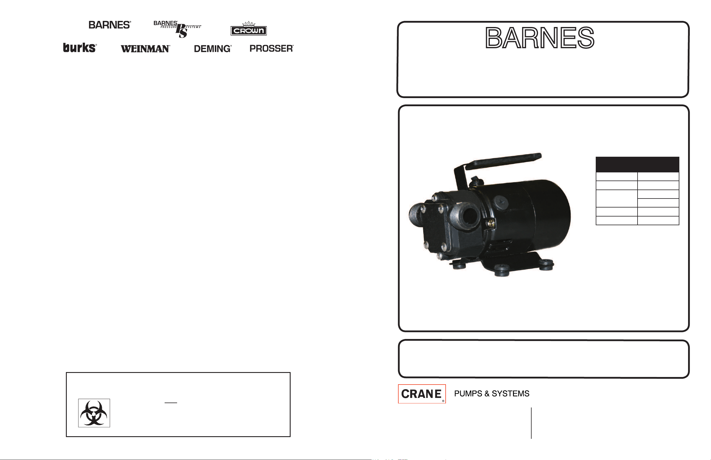
Series: BT12
115 Volts, 1 Phase, 60 Hz
Specifi cations
Model No. BT12
Part No. 134677
Output
1/12 HP
62 W
Rated Head 10’
Rated Flow 5 GPM

TROUBLE SHOOTING
CAUTION! Always disconnect the pump from the
electrical power source before handling. If the system
fails to operate properly, carefully read instructions and
perform maintenance recommendations.
If operating problems persist, the following chart may
be of assistance in identifying and correcting them:
MATCH “CAUSE” NUMBER WITH
CORRELATING “CORRECTION” NUMBER.
NOTE: Not all problems and corrections will apply to
each pump model.
PROBLEM CAUSE CORRECTION
Pump will not
run
1. Poor electrical
connection, blown fuse,
tripped breaker or other
interruption of power,
improper power supply.
2. Switch will not activate
pump or is defective.
3. Insuffi cient liquid level.
1. Check
all electrical
connections for
security. Check
for blown fuses,
tripped circuit
breakers or tripped
GFCI outlets.
2. Reposition
pump or clean
pump/basin
as required to
provide adequate
clearance for fl oat.
3. Make sure liquid
level is at least
equal to suggested
turn-on point.
4. Recheck all
sizing calculations
to determine proper
pump size.
5. Check discharge
line for restrictions,
including ice if line
passes through or
into cold areas.
6. Remove and
examine check
valve for proper
installation and
freedom of
operation.
7. Open valve.
8. Check impeller
for freedom of
operation, security
and condition.
Clean impeller
and inlet of any
obstruction.
9. Repair fi xtures
as required to
eliminate leakage.
10. Check pump
temperature limits
& fl uid temperature.
11. Replace portion
of discharge
pipe with fl exible
connector.
12. Check for leaks
around basin inlet
and outlets.
Pump will not
turn off
2. Switch will not activate
pump or is defective.
4. Excessive infl ow or
pump not properly sized
for application.
Pump hums but
does not run
1. Incorrect voltage
8. Impeller jammed or
loose on shaft, worn or
damaged, inlet plugged.
Pump delivers
insuffi cient
capacity
1. Incorrect voltage.
4. Excessive infl ow or
pump not properly sized
for application.
5. Discharge restricted.
6. Check valve stuck
closed or installed
backwards.
7. Shut-off valve closed.
8. Impeller jammed or
loose on shaft, worn or
damaged, inlet plugged.
Pump cycles
too frequently or
runs periodically
when fi xtures
are not in use
6. Check valve stuck
closed or installed
backwards.
9. Fixtures are leaking.
12. Ground water entering
basin.
Pump shuts off
and turns on
independent of
switch, (trips
thermal overload
protector).
CAUTION!
Pump may start
unexpectedly.
Disconnect
power supply.
1. Incorrect voltage.
4. Excessive infl ow or
pump not properly sized
for application.
8. Impeller jammed,
loose on shaft, worn or
damaged, inlet plugged.
10. Excessive water
temperature.
Pump operates
noisily or
vibrates
excessively
5. Discharge restricted.
8. Impeller broken.
11. Piping attachments to
building structure too rigid
or too loose.
Examine the inlet and outlet hoses to insure there are no blockages, kinks or bends. 3.
The inlet hose should be no longer than 15 feet and the vertical pumping distance
should not be any higher than 10 feet.
Connect pump to power source, with pump in a dry location. Plug into a 3-prong 4.
ground-type AC receptacle.
Do NOT operate the pump continuously above a discharge pressure of 28’ as the 5.
motor will exceed safe operating temperature.
MAINTENANCE:
Always disconnect power source before attempting to install, service, or
maintain the pump.
IMPELLER REPLACEMENT
These parts are designed to handle most clear, non ammable liquids with slight amounts
of abrasives. When impeller vanes become worn from use, or damaged due to pumping
abrasives liquids or trash, pump performance will be reduced or prevented altogether.
Remove the four cover plate screws holding motor housing and pump housing 6.
together. Cover plate is now free and can be removed.
Inspect gasket and impeller for wear and damage. If there is any evidence or wear or 7.
damges, replace the part(s).
Lubricate new impeller with white grease or lightweight oil and reinstall by aligning 8.
at on impeller hub with at on motor shaft.
Reassemble gasket, cover plate, and cover plate screws.9.
SHAFT SEAL REPLACEMENT
Motor shafts are sealed with factory pre-lubricated lip-type seals which aregood for the
life of the pump. If the seal leaks, it is usually because the pump has handled abrasive
liquids. If the motor shaft is scored (deep grooves), the complete pump must be replaced.
Remove and inspect impeller parts as speci ed in the impeller replacement 1.
instructions. Replace worn parts.
Remove two pump body mounting screws and slide pump body from motor. Pry out 2.
seal retaining ring and push worn shaft seal from inside of pump body.
Lubricate new seal with lightweight oil, push it into pump body with lip facing away 3.
from motor, and push in seal retaining ring.
Reassemble pump body onto motor with mounting screws. Follow steps 3 and 4 in 4.
IMPELLER REPLACEMENT.
MOTOR BRUSH REPLACEMENT
Brushes for this pump should be inspected after 75 hours of operation and replace if
worn. They must be replaced every 150 hour of operation. Service one brush at a time.
Disconnect pump from power supply.1.
Remove brush caps with screwdriver.2.
Remove old brush assembly.3.
Insert new brush assembly.4.
Replace brush caps 5.
Item No. Qty. Description
A 1 Impeller
B 2 Gasket
C 1 Shaft Seal
D 1 Retaining Ring
E 2 Brushes
F 1 Water Suction Attachment
G 1 6ft. Suction Hose
Please Read This Before Installing Or Operating
Pump. This information is provided for SAFETY and
to PREVENT EQUIPMENT PROBLEMS. To help
recognize this information, observe the following
symbols:
IMPORTANT! Warns about hazards that can
result in personal injury or Indicates factors
concerned with assembly, installation,
operation, or maintenance which could result
in damage to the machine or equipment if
ignored.
CAUTION! Warns about hazards that can or will
cause minor personal injury or property damage if
ignored. Used with symbols below.
WARNING! Warns about hazards that can or will
cause serious personal injury, death, or major property
damage if ignored. Used with symbols below.
Only qualifi ed personnel should install, operate and
repair pump. Any wiring of pumps should be performed
by a qualifi ed electrician.
WARNING ! To reduce risk of electrical
shock, pumps and control panels must
be properly grounded in accordance with
the National Electric Code (NEC) or the
Canadian Electrical Code (CEC) and all
applicable state, province, local codes
and ordinances. Improper grounding voids
warranty.
WARNING! To reduce risk of electrical
shock, always disconnect the pump from the
power source before handling or servicing.
Lock out power and tag.
WARNING! Operation against
a closed discharge valve will
cause premature bearing and
seal failure on any pump, and
on end suction and self priming pump the heat build
may cause the generation of steam with resulting
dangerous pressures. It is recommended that a high
case temperature switch or pressure relief valve be
installed on the pump body.
CAUTION ! Never operate a pump with a
plug-in type power cord without a ground
fault circuit interrupter.
CAUTION ! Pumps build up heat
and pressure during operation-
allow time for pumps to cool before
handling or servicing.
WARNING ! Do not pump hazardous
materials (fl ammable, caustic, etc.) unless
the pump is specifi cally designed and
designated to handle them.
CAUTION ! Do not block or restrict discharge
hose, as discharge hose may whip under
pressure.
WARNING ! Do not wear loose clothing that
may become entangled in moving parts.
WARNING ! Keep clear of suction and
discharge openings. DO NOT insert fi ngers
in pump with power connected.
Always wear eye protection when working
on pumps.
Make sure lifting handles are securely
fastened each time before lifting. DO NOT
operate pump without safety devices in
place. Always replace safety devices that
have been removed during service or repair.
Secure the pump in its operating position so
it can not tip over, fall or slide.
DO NOT exceed manufacturers
recommendation for maximum performance,
as this could cause the motor to overheat.
DO NOT remove cord and strain relief.
DO NOT connect conduit to pump.
WARNING ! Cable should be protected at
all times to avoid punctures, cut, bruises
and abrasions. Inspect frequently. Never
handle connected power cords with wet
hands.
WARNING ! To reduce risk of electrical
shock, all wiring and junction connections
should be made per the NEC or CEC and
applicable state or province and local
codes. Requirements may vary depending
on usage and location.
WARNING! Submersible Pumps are not
approved for use in swimming pools,
recreational water installations decorative
fountains or any installation where human
contact with the pumped fl uid is common.
WARNING! Products returned must be
cleaned, sanitized, or decontaminated
as necessary prior to shipment, to insure
that employees will not be exposed to
health hazards in handling said material.
All Applicable Laws And Regulations Shall
Apply.
Bronze/brass and bronze/brass fi tted
pumps may contain lead levels higher than
considered safe for potable water systems.
Lead is known to cause cancer and birth
defects or other reproductive harm. Various
government agencies have determined that
leaded copper alloys should not be used in
potable water applications. For non-leaded
copper alloy materials of construction,
please contact factory.
Crane Pumps & Systems, Inc. is not
responsible for losses, injury, or death
resulting from a failure to observe these
safety precautions, misuse or abuse of
pumps or equipment.
SAFETY FIRST!
Hazardous fl uids
can cause fi re
or explosions,
burns or death
could result.
Extremely hot
- Severe burns
can occur on
contact.
Biohazard can
cause serious
personal injury.
Hazardous fl uids
can Hazardous
pressure,
eruptions or
explosions could
cause personal
injury or property
damage.
Rotating
machinery
Amputation
or severe
laceration
can result.
Hazardous
voltage can
shock, burn or
cause death.
Other brand and product names are trademarks or registered trademarks of their respective holders.
® Barnes is a registered trademark of Crane Pumps & Systems, Inc.
2012 Alteration Rights Reserved
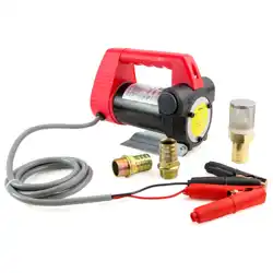
DESCRIPTION: These self-priming transfer pumps are
designed to easily transfer water from one point to another.
Model BT12, 115 Volt Transfer Pump is great for household
usage. Typical applications include removing water from
waterbeds, clogged sinks, basements, etc. NOTE: Do
NOT use BT12 in pool areas. The motor model is non-
submersible with overload protection.
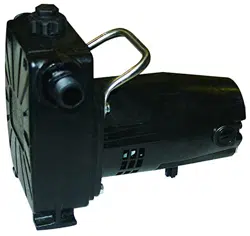
INSTALLATION: Model BT12 includes a 6’ suction hose,
a water suction attachment, and a replacement parts kit
which includes; impeller, gasket, shaft seal, and two motor
brushes. Model BT12 can be used without the water suction
attachment.
Always disconnect power source before
attempting to install, service, or maintain the
pump. Never handle a pump with wet hands
or when standing on wet r damp surface or in
water. Fatal electrical shock could occur.
A ground fault circuit interrupter (GFCI) is required. 1.
Risk of electrical shock! This pump is supplied
with a grounding conductor and grounding
type attachment plug. A grounded receptacle in
conformance with current NEC and local codes
must be used (See Figure 1). Do NOT use in
swimming pool areas.
Model BT12 operates on 115V only.2.
Use an extension cord only if necessary. Follow the 3.
Extension Cord Length Table at the bottom of the page
for proper gage of 3-wire, grounding type extension
cord.
Risk of fatal electrical shock! Never cut o the
round grounding prong. Cutting the cord or
plug will void the warranty and make the pump
inoperable.
Use a strainer when pumping from a creek, pond, or 4.
source where foreign objects may be sucked into the
pump. The strainer should prevent solids from entering
the inlet line.
A regular garden hose may be used as a discharge line.5.
Pump operation will be seriously hindered or prevented 6.
if the inlet hose is over 15 feet long or if the vertical
pumping distance exceeds 10 feet.
At times, an overload due to over heating, low voltage, 7.
jammed impeller, etc. may shut the pump o . Unplug
or turn o the pump and wait at lease ten minutes. The
pump will cool and automatically reset.
Motor should never be operated for more than 2 hours 8.
continuously. Critical heating can occur and might
severely damage the pump and void warranty.
OPERATION:
Add 1 tablespoon of vegetable oil to both inlet and 1.
outlet to prime.
Attach included 6’ suction hose to inlet of pump. Attach 2.
garden hose to outlet of pump. There must be a gasket
in place to insure that these connections are airtight,
otherwise the pump will not prime. Connect water
suction attachment to the open end of inlet hose and
place below water surface. (Water suction attachment is
optional). The water suction attachment is designed to t
the male end of a garden hose. Place the water suction
attachment as near as possible to the middle of the
water that is to be pumped.
Figure 1