Loading ...
Loading ...
Loading ...
i i i iiiii ii i iiiiiiiiiiiiiiiii
SERVICE AN
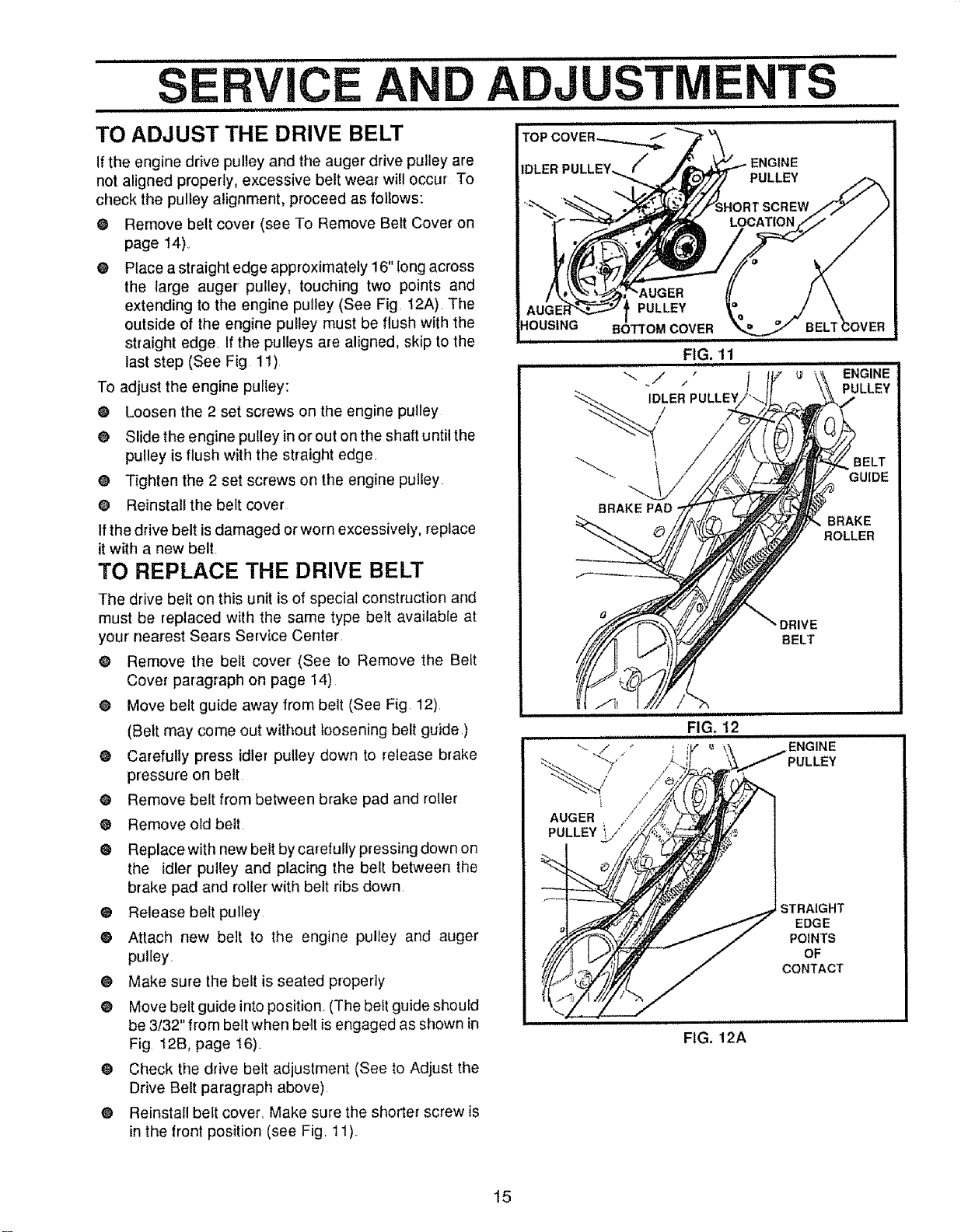
TO ADJUST THE DRIVE BELT
Ifthe engine drive pulley and the auger drive pulley are
not aligned properly, excessive belt wear will occur To
check the pulley alignment, proceed as follows:
O Remove belt cover (see To Remove Belt Cover on
page 14)_
® Place a straight edge approximately 16" long across
the large auger pulley, touching two points and
extending to the engine pulley (See Fig, 12A)The
outside of the engine putley must be flush with the
straight edge. If the pulleys are aligned, skip to the
last step (See Fig 11)
To adjust the engine pulley:
® Loosen the 2 set screws on the engine pulley
O Slide the engine pulley in or out on the shaft until the
pulley isflush with the straight edge,
O Tighten the 2 set screws on the engine pulley
O Reinstallthe beJt cover
If the drive belt isdamaged or worn excessively, replace
it with a new belt,
TO REPLACE THE DRIVE BELT
The drive belt on this unit isof special construction and
must be replaced with the same type belt available at
your nearest Sears Service Center
@ Remove the belt cover (See to Remove the BeLt
Cover paragraph on page 14)
O Move belt guide away from belt (See Fig, 12)
(Belt may come out without loosening belt guide)
O Carefully press idler pulley down to release brake
pressure on belt
O Remove belt from between brake pad and roller
O Remove old belt
@ Replace with new belt by carefully pressing down on
the idler pulley and placing the belt between the
brake pad and roller with belt ribs down,
O Release belt pulley
O Attach new belt to the engine pulley and auger
pulley,
O Make sure the belt is seated properly
@ Move belt guide into position_ (The belt guide shouEd
be 3/32" from belt when belt is engaged as shown in
Fig 12B, page 16)_
® Check the drive belt adjustment (See to Adjust the
Drive Belt paragraph above).
O Reinstall belt cover, Make sure the shorter screw is
in the front position (see Fig, 11)
ii ii iiiiiiiiii ii ii iiiiii
ADJUST E TS
FIG. 11
iiii
BRAKEPAD-
ENGINE
PULLEY
]ELT
GUIDE
BRAKE
ROLLER
BELT
ii iiiiiiiiiiii
]%
/ ,*/
/
AUGER /
PULLEY _/"
FIG. 12
i,i
ENGINE
_ULLEY
STRAIGHT
EDGE
POINTS
OF
CONTACT
FIG. 12A
15
Loading ...
Loading ...
Loading ...