
WARNING: To reduce the risk of injury, the user must read and understand the
Owner’s Manual before using this product. Save these instructions for future reference.
Owner’s Manual
For Customer Service
Pour le service à la clientèle
Servicio al cliente
20V Brushless Impact Wrench
1-877-SKIL-999
OR
www.skil.com
Model: IW5739-00

2
TABLE OF CONTENTS
General Power Tool Safety Warnings .............................3-5
Safety Warnings for Impact Wrench ................................5
Symbols .....................................................6-9
Get to Know Your Impact Wrench .................................10
Specications .................................................10
Operating Instructions .......................................11-15
Maintenance ...................................................16
Trouble Shooting ...............................................16
Limited Warranty of Skil Cordless Tool .............................17
WARNING
•
Some dust created by power sanding, sawing, grinding, drilling and other construction
activities contains chemicals known to the State of California to cause cancer, birth defects
or other reproductive harm. Some examples of these chemicals are:
–
Lead from lead-based paints.
–
Crystalline silica from bricks, cement, and other masonry products.
–
Arsenic and chromium from chemically-treated lumber.
•
Your risk from these exposures varies, depending upon how often you do this type of work.
To reduce your exposure to these chemicals:
–
Work in a well-ventilated area.
–
Work with approved safety equipment, such as dust masks that are specially designed to
lter out microscopic particles.
–
Avoid prolonged contact with dust from power sanding, sawing, grinding, drilling, and
other construction activities. Wear protective clothing and wash exposed areas with soap
and water. Allowing dust to get into your mouth or eyes or to lie on the skin may promote
absorption of harmful chemicals.

3
General Power Tool Safety Warnings
WARNING
Read all safety warnings, instructions, illustrations and specications
provided with this power tool.
Failure to follow all instructions listed
below may result in electric shock, re and/or serious injury.
SAVE ALL WARNINGS AND INSTRUCTIONS FOR FUTURE
REFERENCE.
The term “power tool” in the warnings refers to your mains-operated (corded) power tool or
battery-operated (cordless) power tool.
Work area safety
Keep work area clean and well lit
. Cluttered or dark areas invite accidents.
Do not operate power tools in explosive atmospheres, such as in the presence of
ammable liquids, gases or dust.
Power tools create sparks which may ignite the dust or
fumes.
Keep children and bystanders away while operating a power tool.
Distractions can cause
you to lose control.
Electrical safety
Power tool plugs must match the outlet. Never modify the plug in any way. Do not use
any adapter plugs with earthed (grounded) power tools.
Unmodied plugs and matching
outlets will reduce risk of electric shock.
Avoid body contact with earthed or grounded surfaces, such as pipes, radiators,
ranges and refrigerators.
There is an increased risk of electric shock if your body is earthed
or grounded.
Do not expose power tools to rain or wet conditions.
Water entering a power tool will
increase the risk of electric shock.
Do not abuse the cord. Never use the cord for carrying, pulling or unplugging the power
tool. Keep cord away from heat, oil, sharp edges or moving parts.
Damaged or entangled
cords increase the risk of electric shock.
When operating a power tool outdoors, use an extension cord suitable for outdoor use.
Use of a cord suitable for outdoor use reduces the risk of electric shock.
If operating a power tool in a damp location is unavoidable, use a ground fault circuit
interrupter (GFCI) protected supply.
Use of a GFCI reduces the risk of electric shock.
Personal safety
Stay alert, watch what you are doing and use common sense when operating a power
tool. Do not use a power tool while you are tired or under the inuence of drugs,
alcohol or medication.
A moment of inattention while operating power tools may result in
serious personal injury.
Use personal protective equipment. Always wear eye protection.
Protective equipment
such as a dust mask, non-skid safety shoes, hard hat or hearing protection used for
appropriate conditions will reduce personal injuries.
Prevent unintentional starting. Ensure the switch is in the off-position before
connecting to power source and/or battery pack, picking up or carrying the tool.
Carrying power tools with your nger on the switch or energising power tools that have the
switch on invites accidents.
Remove any adjusting key or wrench before turning the power tool on.
A wrench or a
key left attached to a rotating part of the power tool may result in personal injury.

4
Do not overreach. Keep proper footing and balance at all times.
This enables better
control of the power tool in unexpected situations.
Dress properly. Do not wear loose clothing or jewellery. Keep your hair and clothing
away from moving parts.
Loose clothes, jewellery or long hair can be caught in moving
parts.
If devices are provided for the connection of dust extraction and collection facilities,
ensure these are connected and properly used.
Use of dust collection can reduce dust-
related hazards.
Do not let familiarity gained from frequent use of tools allow you to become complacent
and ignore tool safety principles.
A careless action can cause severe injury within a fraction
of a second.
Power tool use and care
Do not force the power tool. Use the correct power tool for your application.
The correct
power tool will do the job better and safer at the rate for which it was designed.
Do not use the power tool if the switch does not turn it on and off.
Any power tool that
cannot be controlled with the switch is dangerous and must be repaired.
Disconnect the plug from the power source and/or remove the battery pack, if
detachable, from the power tool before making any adjustments, changing accessories,
or storing power tools.
Such preventive safety measures reduce the risk of starting the
power tool accidentally.
Store idle power tools out of the reach of children and do not allow persons unfamiliar
with the power tool or these instructions to operate the power tool.
Power tools are
dangerous in the hands of untrained users.
Maintain power tools and accessories. Check for misalignment or binding of moving
parts, breakage of parts and any other condition that may affect the power tool’s
operation. If damaged, have the power tool repaired before use.
Many accidents are
caused by poorly maintained power tools.
Keep cutting tools sharp and clean.
Properly maintained cutting tools with sharp cutting
edges are less likely to bind and are easier to control.
Use the power tool, accessories and tool bits etc. in accordance with these instructions,
taking into account the working conditions and the work to be performed.
Use of the
power tool for operations different from those intended could result in a hazardous situation.
Keep handles and grasping surfaces dry, clean and free from oil and grease.
Slippery
handles and grasping surfaces do not allow for safe handling and control of the tool in
unexpected situations.
Battery tool use and care
Recharge only with the charger specied by the manufacturer
. A charger that is suitable
for one type of battery pack may create a risk of re when used with another battery pack.
Use power tools only with specically designated battery packs.
Use of any other battery
packs may create a risk of injury and re.
When battery pack is not in use, keep it away from other metal objects, like paper clips,
coins, keys, nails, screws or other small metal objects, that can make a connection
from one terminal to another
. Shorting the battery terminals together may cause burns or a
re.
Under abusive conditions, liquid may be ejected from the battery; avoid contact. If
contact accidentally occurs, ush with water. If liquid contacts eyes, additionally seek
medical help
. Liquid ejected from the battery may cause irritation or burns.
Do not use a battery pack or tool that is damaged or modied
. Damaged or modied

5
batteries may exhibit unpredictable behaviour resulting in re, explosion or risk of injury.
Do not expose a battery pack or tool to re or excessive temperature
. Exposure to re or
temperature above 265 °F may cause explosion.
Follow all charging instructions and do not charge the battery pack or tool outside the
temperature range specied in the instructions.
Charging improperly or at temperatures
outside the specied range may damage the battery and increase the risk of re.
Service
Have your power tool serviced by a qualied repair person using only identical
replacement parts.
This will ensure that the safety of the power tool is maintained.
Never service damaged battery packs.
Service of battery packs should only be performed
by the manufacturer or authorized service providers.
SAFETY WARNINGS FOR IMPACT WRENCH
Hold the power tool by insulated gripping surfaces, when performing an operation
where the fastener may contact hidden wiring.
Fasteners contacting a “live” wire may
make exposed metal parts of the power tool “live” and could give the operator an electric
shock.
6
SYMBOLS
Safety Symbols
The purpose of safety symbols is to attract your attention to possible dangers. The safety
symbols and the explanations with them deserve your careful attention and understanding.
The symbol warnings do not, by themselves, eliminate any danger. The instructions and
warnings they give are no substitutes for proper accident prevention measures.
WARNING
Be sure to read and understand all safety instructions in this Owner's
Manual, including all safety alert symbols such as “
DANGER
,”
“
WARNING
,” and “
CAUTION
” before using this tool. Failure to following all instructions listed
below may result in electric shock, re, and/or serious personal injury.
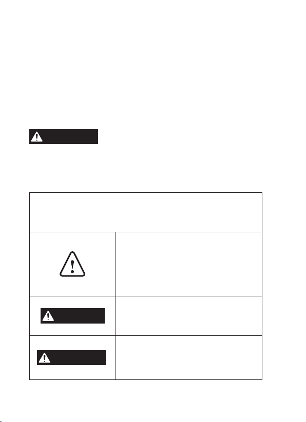
The denitions below describe the level of severity for each signal word. Please read the manual
and pay attention to these symbols.
This is the safety alert symbol. It is used to alert you to potential
personal injury hazards. Obey all safety messages that follow this
symbol to avoid possible injury or death.
DANGER
DANGER indicates a hazardous situation which, if not avoided, will
result in death or serious injury.
WARNING
WARNING indicates a hazardous situation which, if not avoided, could
result in death or serious injury.
CAUTION
CAUTION, used with the safety alert symbol, indicates a hazardous
situation which, if not avoided, will result in minor or moderate injury.
Damage Prevention and Information Messages
These inform the user of important information and/or instructions that could lead to equipment
or other property damage if they are not followed. Each message is preceded by the word
“NOTICE”, as in the example below:
NOTICE:
Equipment and/or property damage may result if these instructions are not followed.
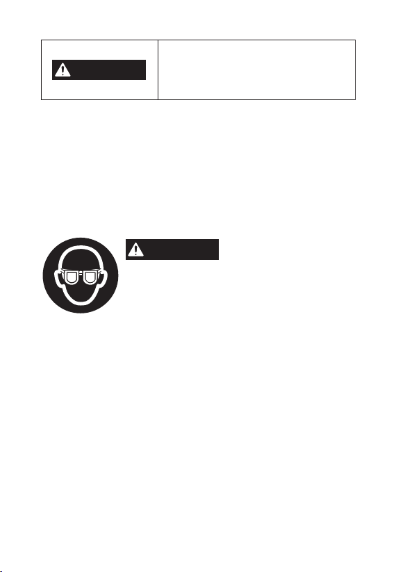
WARNING
The operation of any power tools can result in
foreign
objects being thrown into your eyes, which can result
in severe eye damage. Before beginning power tool operation, always
wear safety goggles or safety glasses with side shields and a full face
shield when needed. We recommend a Wide Vision Safety Mask for use
over eyeglasses or standard safety glasses with side shields. Always use
eye protection which is marked to comply with ANSI Z87.1.

7
SYMBOLS (CONTINUED)
IMPORTANT:
Some of the following symbols may be used on your tool. Please study them
and learn their meaning. Proper interpretation of these symbols will allow you to operate the
tool better and more safely.
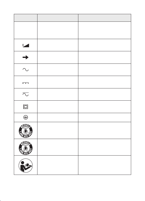
Symbol Name Designation/Explanation
V Volts Voltage (potential)
A Amperes Current
Hz Hertz Frequency (cycles per second)
W Watt Power
kg Kilograms Weight
min Minutes Time
s Seconds Time
Wh Watt-hours Battery capacity
Ah Ampere-Hours Battery capacity
Ø Diameter Size of drill bits, grinding wheels, etc.
n
0
No-load speed Rotational speed, at no load
n Rated speed Maximum attainable speed
…/min
Revolutions or
reciprocations per minute
Revolutions, strokes, surface speed,
orbits, etc. per minute
0 Off position Zero speed, zero torque...
1,2,3,…
I,II,III,
Selector settings
Speed, torque or position settings. Higher
number means greater speed
Innitely variable selector
with off
Speed is increasing from 0 setting
Arrow Action in the direction of arrow
Alternating current Type or a characteristic of current
Direct current Type or a characteristic of current
Alternating or direct current Type or a characteristic of current
Class II tool
Designates Double Insulated Construction
tools.
Earthing terminal Grounding terminal
Li-ion RBRC seal
Designates Li-ion battery recycling
program

8
Symbol Name Designation/Explanation
Ni-Cad RBRC seal
Designates Ni-Cad battery recycling
program
Read manual symbol Alerts user to read manual
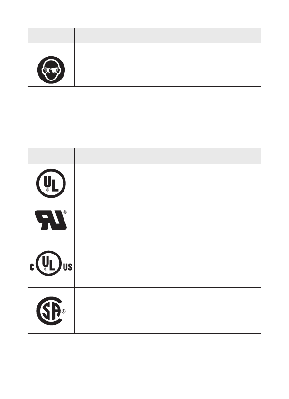
Wear eye protection symbol
Always wear safety goggles or safety
glasses with side shields and a full face
shield when operating this product.
9
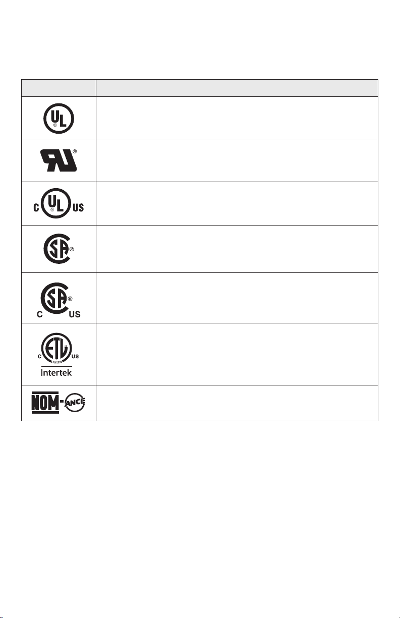
SYMBOLS (CERTIFICATION INFORMATION)
IMPORTANT:
Some of the following symbols for certication information may be used on your
tool. Please study them and learn their meaning. Proper interpretation of these symbols will
allow you to operate the tool better and more safely.
Symbol Designation/Explanation
This symbol designates that this tool is listed by Underwriters Laboratories.
This symbol designates that this tool is recognized by Underwriters
Laboratories.
This symbol designates that this tool is listed by Underwriters
Laboratories, to United States and Canadian Standards.
This symbol designates that this tool is listed by the Canadian
Standards Association.
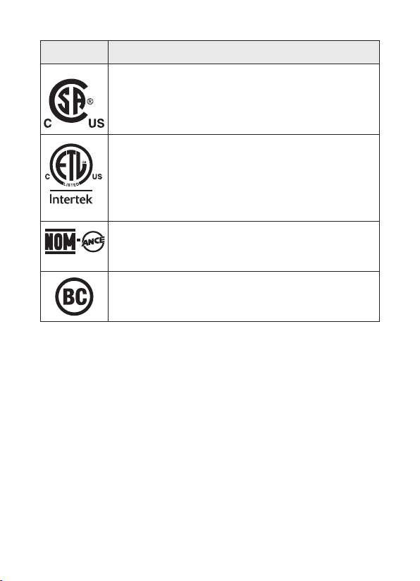
This symbol designates that this tool is listed by the Canadian
Standards Association, to United States and Canadian Standards.
This symbol designates that this tool is listed by the Intertek Testing
Services, to United States and Canadian Standards.
This symbol designates that this tool complies to NOM Mexican
Standards.
10
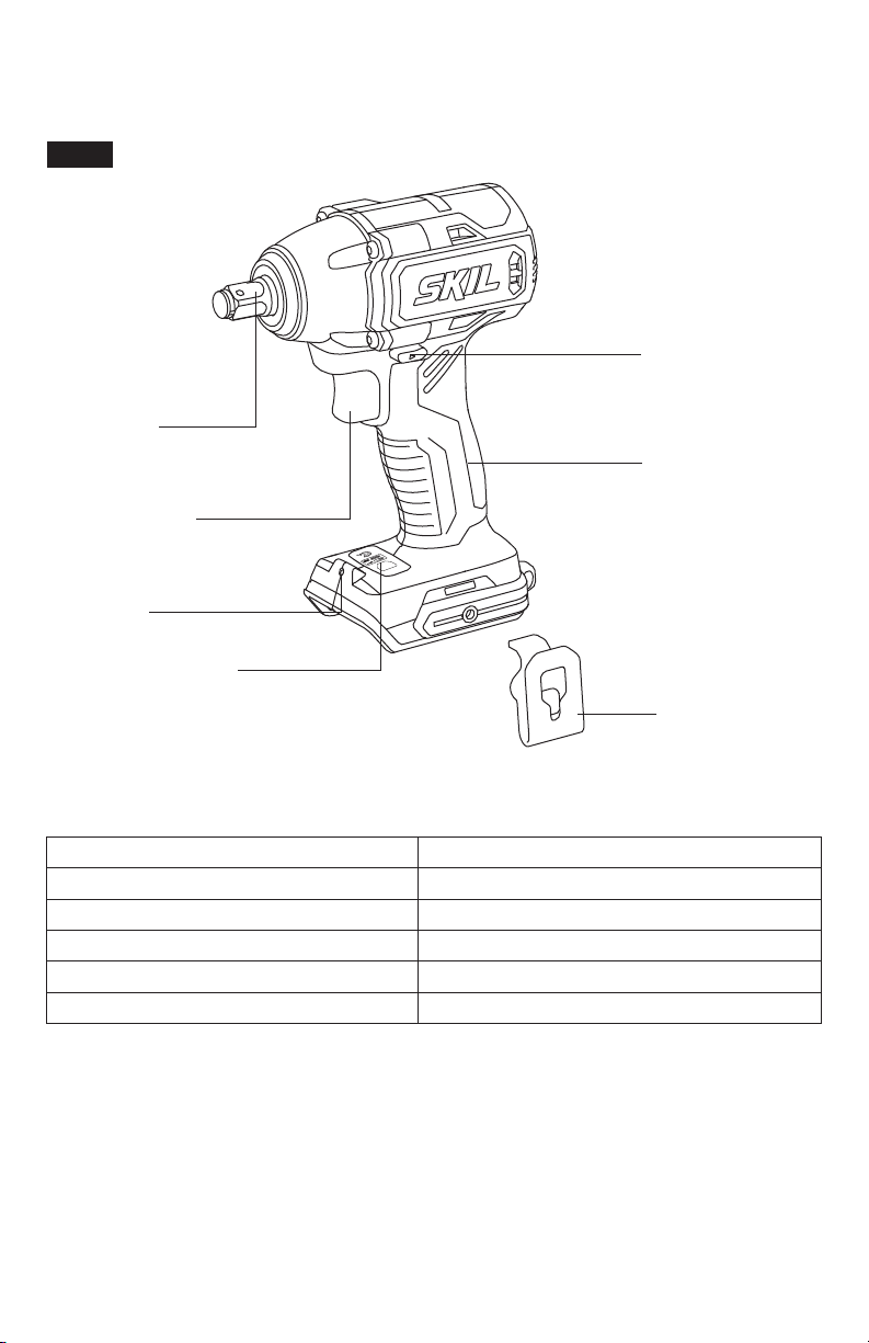
GET TO KNOW YOUR IMPACT WRENCH
20V Brushless Impact Wrench
BRUSHLESS
Mode
Fig. 1
Removable
Belt Clip
1/2" Square
Drive
Direction-of-
Rotation (Forward/
Center-lock/
Reverse) Selector
Soft Grip
Mode-change Button
Variable-Speed
Trigger Switch
LED Light
SPECIFICATIONS
Rated voltage 20V d.c.
Square drive 1/2"
No-load speed 0~2100/0~2400/min
Impacts per minute 0~2800/0~3200 /min
Recommended working temperature 14~104°F (-10~40℃)
Recommended storage temperature 32~104°F (0~40℃)
11
OPERATING INSTRUCTIONS
WARNING
To reduce the risk of re, personal injury, and product damage due to a
short circuit, never immerse your tool, battery pack or charger in uid
or allow a uid to ow inside them.
Corrosive or conductive uids, such as seawater, certain
industrial chemicals, and bleach or bleach-containing products, etc, can cause a short circuit.
WARNING
If any parts are damaged or missing, do not operate this product until
the parts are replaced.
Use of this product with damaged or missing parts
could result in serious personal injury.
WARNING
Do not attempt to modify this Impact Wrench or create accessories
not recommended for use with this Impact Wrench.
Any such alteration
or modication is misuse and could result in a hazardous condition leading to possible serious
injury.
WARNING
To prevent accidental starting that could cause serious personal
injury, always remove the battery pack from the Impact Wrench when
assembling parts, making adjustments, cleaning, or performing maintenance.
This cordless impact wrench must be used only with the battery packs and chargers listed
below:
Battery pack
Charger
2Ah 2Ah 2.5Ah 4Ah 5Ah
SKIL
BY519701
SKIL
BY519702
SKIL
BY519703
SKIL
BY519601
SKIL
BY519603
SKIL
SC535801
SKIL
QC536001
NOTICE:
Please refer to the battery and charger manual for detailed operating information.
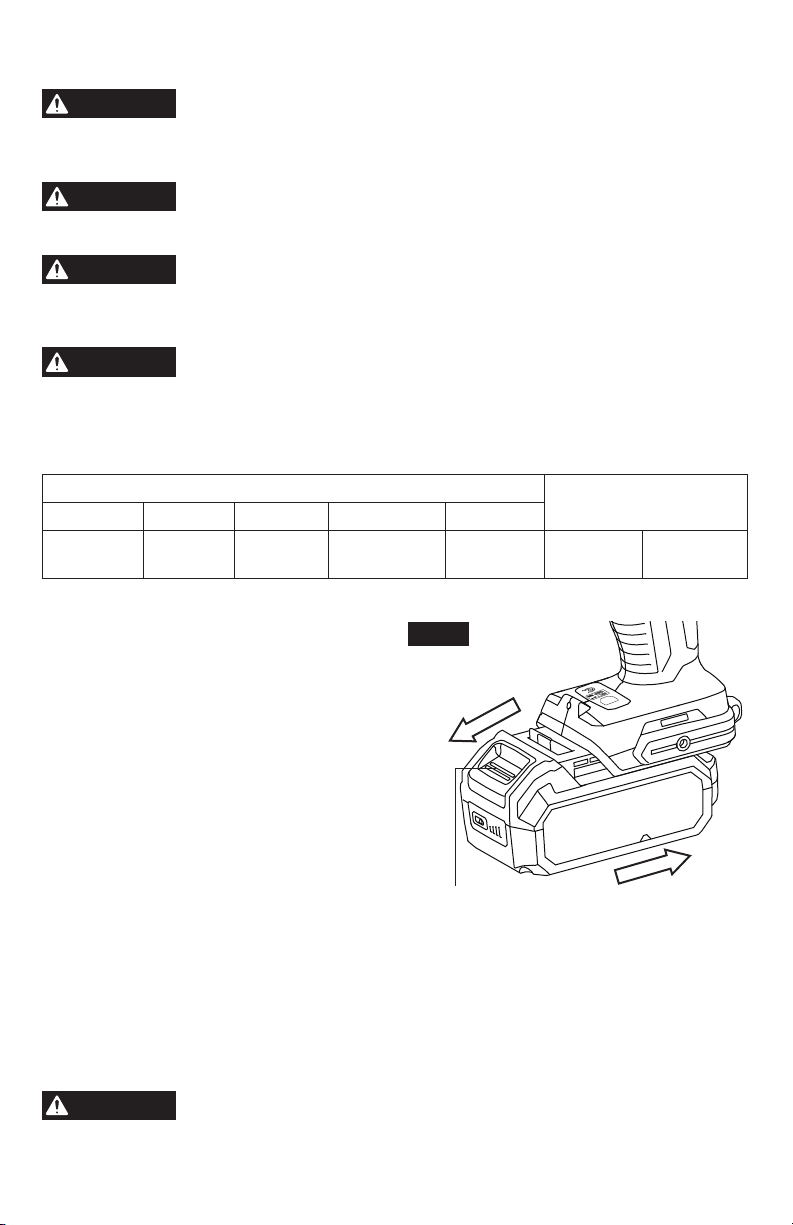
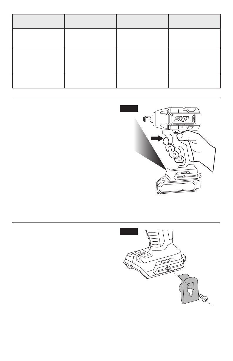
To Attach/Detach Battery Pack
(Fig.2)
Lock the trigger switch “OFF” on the tool by
placing the direction-of-rotation (forward/cen-
ter-lock/reverse) selector in the center position
before attaching or detaching the battery pack.
To attach the battery pack:
Align the raised rib on the battery pack with the
grooves of the tool, and then slide the battery
pack onto the tool.
NOTICE:
Make sure that the latch on the
battery pack snaps into place and that the
battery pack is secured to the tool before
beginning operation.
To detach the battery pack:
Depress the battery-release button located on the front of the battery pack to release the bat-
tery pack. Pull the battery pack out and remove it from the tool.
NOTICE:
When placing the battery pack onto the tool, be sure that the raised rib on the
battery pack aligns with the groove inside the tool and that the latches snap into place
properly. Improper attachment of the battery pack can cause damage to internal components.
WARNING
Battery tools are always in operating condition. Therefore, the
direction-of-rotation (forward/center-lock/reverse) selector should
always be locked in center position when not in use or carrying at your side.
BRUSHLESS
Mode
Fig. 2
Attach
Battery-Release Button
Detach
12
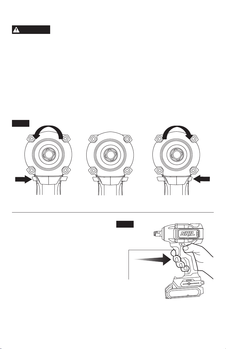
Direction-of-Rotation (Forward/Center-Lock/Reverse) Selector
WARNING
After tool use, lock the direction-of-rotation selector in the
“OFF”position (center-lock) to help prevent accidental starts and
possible injury.
Your tool is equipped with a direction-of-rotation selector, located above the trigger switch.
This selector is used to change the direction of rotation of the bit and to lock the variable-
speed trigger in the “OFF” (center-lock) position (Fig. 3).
a. Position the direction-of-rotation selector to the far right of the tool for forward rotation.
b. Position the direction-of-rotation selector to the far left of the tool for reverse rotation.
c. Setting the switch in “OFF” (center-lock) position helps to reduce the possibility of accidental
starting when not in use.
NOTICE
: To prevent gear damage, always allow the impact wrench to come to a complete
stop before changing the direction of rotation.
NOTICE
: The impact wrench will not run unless the direction-of-rotation selector is engaged
fully to the left or right.
Fig. 3
Forward
ReverseCenter-Lock
Variable-Speed Trigger Switch
Your tool is equipped with a variable-speed
trigger switch. The tool can be turned “ON” or
“OFF” by depressing or releasing the variable-
speed trigger switch.
The variable-speed trigger switch delivers
higher speed with increased trigger pressure
and lower speed with decreased trigger
pressure (Fig. 4).
BRUSHLESS
Fig. 4
Variable Speed
Trigger Switch
13
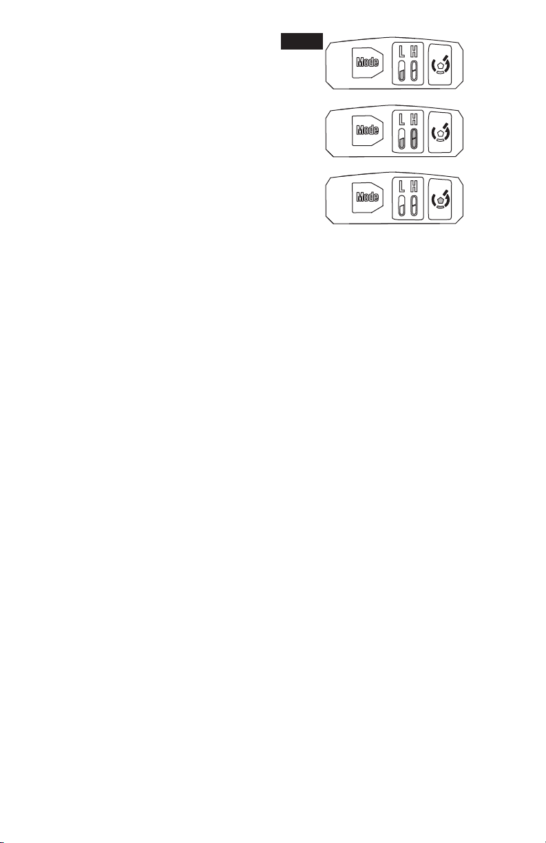
Changing the Impact Force (Fig.5)
a. When the tool rotates clockwise (forward
direction), you can change the impact force
between two modes:
LO Mode
HI Mode.
This allows a tightening force suitable to the
work. Every time the mode-change button is
pressed, the number of mode progresses in
order, as follows:
LO Mode
HI Mode
HI Mode.
•
Indicator light 1 shines green for “LO Mode” to indicate “low-speed mode”.
•
Both indicator light 1 and indicator light 2 shine green for “HI Mode” to indicate “high-speed
mode”.
•
Indicator light 3 shines green to indicate “high-speed mode”, which is same to the HI Mode.
b. When the tool rotates counterclockwise (reverse direction), you can change the impact force
among three modes:
LO Mode
HI Mode
Reverse Control Mode.
Every time the mode-change button is pressed, the mode progresses in order, as follows:
LO Mode
HI Mode
Reverse Control Mode.
•
Indicator light 1 shines green for “LO Mode” to indicate “low-speed mode”.
•
Both indicator light 1 and indicator light 2 shine green for “HI Mode” to indicate “high-speed
mode”.
•
Indicator light 3 shines green to indicate “reverse control mode”.
In reverse control mode, the tool stops the reverse rotation and the impact within seconds
once the fastener is loosened.
NOTICE:
The reverse control mode is available only when the tool rotates counterclockwise
and the trigger switch is fully depressed.
NOTICE:
The impact force mode can be changed only when any mode-indicator light is
shining and the trigger switch is not depressed. The impact force mode cannot be activated
when the motor is running.
The impact force mode will be stored and applied in the next operation when the tool is turned
on again or when the direction of rotation has been changed. Reset the impact modes as
desired.
When the trigger is squeezed slightly, one of the three indicator lights will automatically shine
green, to indicate the force mode stored at the last use and will turn off approximately 60
seconds after the variable speed trigger switch is released. It means that during approximately
one minute after releasing the switch trigger, the impact force can be changed.
1 2 3
3
3
1 2
1 2
Fig. 5
14
Impact force mode
displayed
Maximum IPM
(Impacts per minute)
Purpose
Example of
application
High 3200 min
-1
(/min)
Tightening when
force and speed are
desired.
Assembling steel
frames
Low 2800 min
-1
(/min)
Tightening when you
need ne adjustment
with small diameter
bolt.
Assembling furnitures
Reverse Control
Mode
3200 min
-1
(/min)
Loosening with
automatic control.
Disassembling nuts
or bolts.
LED Light
Your tool is equipped with an LED light, located
on the base of the tool. This provides additional
light on the surface of the work piece for
operation in lower-light areas.
The LED light will automatically turn on with a
slight squeeze on the variable-speed trigger
switch before the tool starts running, and will
turn off approximately 10 seconds after the
variable-speed trigger switch is released.
The LED light will rapidly ash when the tool
and/or battery pack becomes overloaded or
too hot, and the internal sensors will turn the
tool off. Rest the tool for a while or place the
tool and battery pack separately under air ow
to cool them.
The LED light will ash more slowly to indicate that the battery is at low-battery capacity.
Recharge the battery pack.
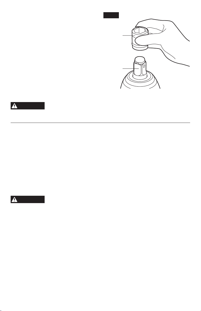
Removable Belt Clip (Fig.7)
Your tool is equipped with removable belt clip,
which can be positioned on the left side of the
tool for convenient transport.
Install the belt clip onto the tool:
a. Remove the battery pack from the tool.
b. Align the rib of the belt clip with the threaded
hole on the base of the tool.
c. Insert the screw and securely tighten the
screw with a screwdriver.
Remove the belt clip from the tool:
d. Remove the battery pack from the tool.
e. Use a screwdriver to loosen the screw that
attaches the belt clip to the impact wrench.
f. Remove the screw and the belt clip.
BRUSHLESS
Fig. 6
BRUSHLESS
Mode
Fig. 7
15
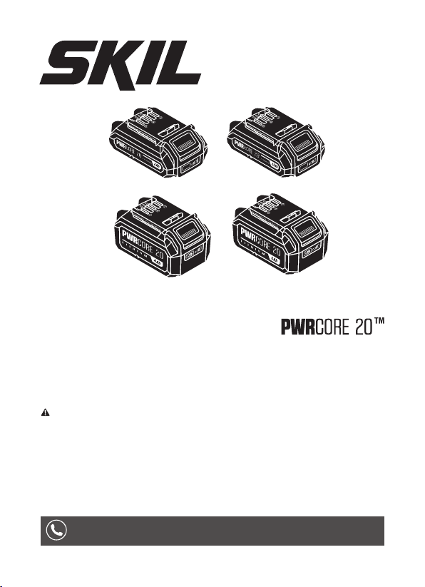
Install and Remove the Impact
Socket (Fig.8)
Lock the trigger switch “OFF” by placing the
direction-of-rotation selector in the center
position.
CAUTION:
Make sure that the impact socket
and the mounting portion are not damaged
before installing the impact socket.
To install the Impact Socket:
a. Align the square of the impact socket with
the square drive and push the impact socket
onto the square drive until it locks into place.
b. Tap it lightly if required.
Remove the Impact Socket:
To remove the impact socket, simply pull it off.
WARNING
Use protective gloves when removing the impact socket from the tool, or
rst allow the impact socket to cool down. The impact socket may be hot
after prolonged use.
Tighten and loosen nuts and bolts
Variable speed control must be used with caution for driving nuts and bolts with socket set
attachments. The technique is to start slowly, increasing speed as the nut or bolt runs downs.
Set the nut or bolt snugly by slowing the tool to a stop. If this procedure is not followed, the
tool will have a tendency to torque or twist in your hands when the nut or bolt seats.
a. Select hex socket that matches the nut or bolt. Then mount the socket on the square drive,
and grip the nut or bolt to be tightened with the hex socket.
b. Hold the tool rmly and apply just enough pressure to keep the socket engaged on the nut
or bolt. Then press the trigger switch to impact the nut or bolt for several seconds.
NOTICE:
Always use the correct size impact socket for bolts and nuts. An incorrect size
impact socket will result in inaccurate and inconsistent fastening torque and/or damage to the
bolt or nut.
WARNING
Do not over-tighten, as the force of the impact tool can break the fastener.
Hold the tool vertical with the bolt or nut, otherwise the head of the bolt or
nut will be damaged.
Fig. 8
Square
Drive
Impact
Socket

16
MAINTENANCE
WARNING
To avoid serious personal injury, always remove the battery pack
from the tool when cleaning or performing any maintenance.
Service
WARNING
Preventive maintenance performed by unauthorized personnel may
result in misplacing of internal wires and components which could
cause serious hazard.
We recommend that all tool service be performed by a Skil Factory
Service Center or Authorized Skil Service Station.
General Maintenance
WARNING
When servicing, use only identical replacement parts. Use of any other
parts could create a hazard or cause product damage.
NOTE:
Periodically inspect the entire product for damaged, missing, or loose parts such as
screws, nuts, bolts, caps, etc. Tighten securely all fasteners and caps and do not operate this
product until all missing or damaged parts are replaced. Please contact customer service or
an authorized service center for assistance.
Cleaning
WARNING
The tool may be cleaned most effectively with compressed dry air.
Always
wear safety goggles when cleaning tools with compressed air.
Ventilation openings and switch levers must be kept clean and free of foreign matter. Do not
attempt to clean by inserting pointed objects through openings.
WARNING
Certain cleaning agents and solvents damage plastic parts.
Some of
these are: gasoline, carbon tetrachloride, chlorinated cleaning solvents,
ammonia and house hold detergents that contain ammonia.
Storage
Store the tool indoors in a place that is inaccessible to children. Keep away from corrosive
agents.
TROUBLE SHOOTING
Problem Cause Remedy
Tool will not start. 1. Battery pack is depleted. 1. Charge the battery.
2. Tool is over-loaded. 2. Release the variable-speed trigger
switch and try again.
3. Battery pack is over
temperature.
3. Turn off the impact wrench and cool
the battery pack under air ow.
4. Battery pack is not installed
properly.
4. Conrm that the battery is locked
and secured to the tool.
5. Burned out switch. 5. Have the switch replaced by an
Authorized SKIL Service Center or
Service Station.
LED light rapidly
ashes.
1. Tool is over-loaded. 1. Release the trigger switch.
2. Tool is over-temperature. 2. Cool the tool under air ow.

17
LIMITED WARRANTY FOR SKIL CORDLESS TOOL
5 YEARS LIMITED WARRANTY
Chervon North America, Inc. (“Seller”) warrants to the original purchaser only, that all SKIL
consumer POWER TOOLS will be free from defects in material or workmanship for a period
of ve years from date of purchase, if original purchaser registers the product within 30 days
from purchase. BATTERIES AND CHARGERS are warranted for 2 years. Product registration
can be completed online at www.Registermyskil.com. Original purchasers should also retain
their receipt as proof of purchase. THE FIVE-YEAR WARRANTY PERIOD FOR POWER
TOOLS IS CONDITIONED ON REGISTRATION OF THE PRODUCT WITHIN 30 DAYS OF
PURCHASE. If original purchasers do not register their product timely, the foregoing limited
warranty will apply for a duration of three years for power tools. All batteries and chargers will
remain under the two-year limited warranty.
Notwithstanding the foregoing, if a SKIL consumer portable power tool is used for industrial,
professional or commercial purposes, the foregoing warranty will apply for a duration of ninety
days, regardless of registration.
SELLER’S SOLE OBLIGATION AND YOUR EXCLUSIVE REMEDY under this Limited
Warranty and, to the extent permitted by law, any warranty or condition implied by law, shall
be the repair or replacement of parts, without charge, which are defective in material or
workmanship and which have not been misused, carelessly handled, or repaired by persons
other than Seller or Authorized Service Station. To make a claim under this Limited Warranty,
you must return the complete product, transportation prepaid, to any SKIL Factory Service
Center or Authorized Service Station. For Authorized SKIL Power Tool Service Stations,
please visit www.Registermyskil.com or call 1-877-SKIL-999 (1-877-754-5999).
THIS LIMITED WARRANTY DOES NOT APPLY TO ACCESSORY ITEMS SUCH AS
CIRCULAR SAW BLADES, DRILL BITS, ROUTER BITS, JIGSAW BLADES, SANDING
BELTS, GRINDING WHEELS AND OTHER RELATED ITEMS.
ANY IMPLIED WARRANTIES APPLICABLE TO A PRODUCT SHALL BE LIMITED IN
DURATION EQUAL TO THE DURATION OF THE EXPRESS WARRANTIES APPLICABLE
TO SUCH PRODUCT, AS SET FORTH IN THE FIRST PARAGRAPH ABOVE. SOME STATES
IN THE U.S., SOME CANADIAN PROVINCES DO NOT ALLOW LIMITATIONS ON HOW
LONG AN IMPLIED WARRANTY LASTS, SO THE ABOVE LIMITATION MAY NOT APPLY TO
YOU.
IN NO EVENT SHALL SELLER BE LIABLE FOR ANY INCIDENTAL OR CONSEQUENTIAL
DAMAGES (INCLUDING BUT NOT LIMITED TO LIABILITY FOR LOSS OF PROFITS)
ARISING FROM THE SALE OR USE OF THIS PRODUCT. SOME STATES IN THE U.S.
AND SOME CANADIAN PROVINCES DO NOT ALLOW THE EXCLUSION OR LIMITATION
OF INCIDENTAL OR CONSEQUENTIAL DAMAGES, SO THE ABOVE LIMITATION OR
EXCLUSION MAY NOT APPLY TO YOU.
THIS LIMITED WARRANTY GIVES YOU SPECIFIC LEGAL RIGHTS, AND YOU MAY ALSO
HAVE OTHER RIGHTS WHICH VARY FROM STATE TO STATE IN THE U.S., PROVINCE
TO PROVINCE IN CANADA AND FROM COUNTRY TO COUNTRY.
THIS LIMITED WARRANTY APPLIES ONLY TO PRODUCTS SOLD WITHIN THE UNITED
STATES OF AMERICA, CANADA AND THE COMMONWEALTH OF PUERTO RICO. FOR
WARRANTY COVERAGE WITHIN OTHER COUNTRIES, CONTACT YOUR LOCAL SKIL
DEALER OR IMPORTER.
© Chervon North America, 1203 E. Warrenville Rd, Naperville, IL 60563.
08/19
1-877-SKIL-999
OR
www.skil.com
For Customer Service
Pour le service à la clientèle
Servicio al cliente
WARNING: To reduce the risk of injury, the user must read and understand the
Owner’s Manual before using this product. Save these instructions for future reference.
Owner’s Manual
20V Lithium Battery with Fuel Gauge
Model: BY519701 / BY519703 / BY519601 / BY519603

2
TABLE OF CONTENTS
Safety Instructions ...............................3-6
Symbols .......................................7-12
Get to Know Your Battery ...........................13
Specications ....................................13
Operating Instructions ..........................14-16
Maintenance ...................................17-18
Battery Care ......................................18
Battery Disposal ..................................19
Limited Warranty of SKIL Battery Pack ............. 20-21

3
SAFETY INSTRUCTIONS
WARNING
Read all safety warnings, instructions,
illustrations and specications.
Failure to
follow all instructions listed below may result in electric shock, re
and/or serious injury.
SAVE ALL WARNINGS AND INSTRUCTIONS FOR
FUTURE REFERENCE.
The term “power tool” in the warnings refers to your mains-operated
(corded) power tool or battery-operated (cordless) power tool.
Work area safety
Keep work area clean and well lit.
Cluttered or dark areas invite
accidents.
Do not operate power tools in explosive atmospheres, such as
in the presence of ammable liquids, gases or dust.
Power tools
create sparks which may ignite the dust or fumes.
Electrical safety
Do not expose power tools to rain or wet conditions.
Water
entering a power tool will increase the risk of electric shock.
Battery tool use and care
Recharge only with the charger specied by the manufacturer.
A charger that is suitable for one type of battery pack may create a
risk of re when used with another battery pack.
Use power tools only with specically designated battery
packs.
Use of any other battery packs may create a risk of injury
and re.
When battery pack is not in use, keep it away from other metal
objects, like paper clips, coins, keys, nails, screws or other
small metal objects, that can make a connection from one
terminal to another.
Shorting the battery terminals together may
cause burns or a re.

4
Under abusive conditions, liquid may be ejected from the
battery; avoid contact. If contact accidentally occurs, ush with
water. If liquid contacts eyes, additionally seek medical help.
Liquid ejected from the battery may cause irritation or burns.
Do not use a battery pack or tool that is damaged or modied.
Damaged or modied batteries may exhibit unpredictable behaviour
resulting in re, explosion or risk of injury.
Do not expose a battery pack or tool to re or excessive
temperature.
Exposure to re or temperature above 265 °F may
cause explosion.
Follow all charging instructions and do not charge the battery
pack or tool outside the temperature range specied in the
instructions.
Charging improperly or at temperatures outside the
specied range may damage the battery and increase the risk of
re.
Service
Have your power tool serviced by a qualied repair person
using only identical replacement parts.
This will ensure that the
safety of the power tool is maintained.
Never service damaged battery packs.
Service of battery packs
should only be performed by the manufacturer or authorized service
providers.
Specic Safety Rules
Before using battery, read all instructions and cautionary
markings on (1) battery charger, (2) battery pack, and (3)
product using battery.
Risk of re and burns. Do not recharge, disassemble, heat
above 100 °C(212 °F), or incinerate. Keep battery out of reach
of children and in original package until ready to use.

5
Battery tools do not have to be plugged into an electrical
outlet; therefore, they are always in operating condition. Be
aware of possible hazards when not using your battery tool or
when changing accessories.
Do not place battery tools or their batteries near re or heat.
Charge battery pack within the required temperature range.
Store charger and battery pack in locations where temperature
is within the recommended storage temperature range.
This is
important to prevent serious damage to the battery cells.
Do not crush, drop or damage the battery pack. Do not use a
battery pack or charger that has been dropped or received a
sharp blow.
A damaged battery is subject to explosion. Properly
dispose of a dropped or damaged battery immediately.
Do not insert battery pack in charger if battery pack case is
cracked.
Using damaged battery pack may result in electric shock
or re.
Batteries vent hydrogen gas and can explode in the presence
of a source of ignition such as a pilot light.
To reduce the risk
of serious personal injury, never use any cordless product in the
presence of open ame. An exploded battery can propel debris and
chemicals. If exposed, ush with water immediately.
Do not recharge battery in damp or wet environment. Do not
expose charger to rain or snow.
Water entering battery charger
may result in electric shock or re.
Do not store outside or in vehicles.
Do not store battery pack in charger.
Battery pack stored in
charger over a long period of time could lead to battery pack
damage and re.
Battery leakage may occur under extreme usage or temperature
conditions. Avoid contact with skin and eyes.
The battery liquid
is caustic and could cause chemical burns to tissues. If liquid comes
in contact with skin, wash quickly with soap and water. If the liquid
contacts your eyes, ush them with water for a minimum of 10
minutes and seek medical attention.

6
Do not let gasoline, oils, petroleum-based products, etc. come
in contact with plastic parts.
They contain chemicals that can
damage, weaken or destroy plastic.
Do not touch the uninsulated portion of output connector or
uninsulated battery terminal.
There is a risk of electric shock.
Replace battery pack if a substantial drop in operating time per
charge is observed.
Battery pack may be nearing the end of its
life.
7
Symbols
Safety Symbols
The purpose of safety symbols is to attract your attention to
possible dangers. The safety symbols and the explanations with
them deserve your careful attention and understanding. The
symbol warnings do not, by themselves, eliminate any danger. The
instructions and warnings they give are no substitutes for proper
accident prevention measures.
WARNING
Be sure to read and understand all safety
instructions in this Owner’s Manual, including
all safety alert symbols such as “
DANGER
,” “
WARNING
,” and
“
CAUTION
” before using this tool. Failure to following all instructions
listed below may result in electric shock, re, and/or serious
personal injury.
The denitions below describe the level of severity for each
signal word. Please read the manual and pay attention to these
symbols.
This is the safety alert symbol. It is
used to alert you to potential personal
injury hazards. Obey all safety
messages that follow this symbol to
avoid possible injury or death.
DANGER
DANGER indicates a hazardous
situation which, if not avoided, will
result in death or serious injury.
WARNING
WARNING indicates a hazardous
situation which, if not avoided, could
result in death or serious injury.
8
CAUTION
CAUTION, used with the safety alert
symbol, indicates a hazardous situation
which, if not avoided, will result in
minor or moderate injury.
Damage Prevention and Information Messages
These inform the user of important information and/or instructions
that could lead to equipment or other property damage if they are
not followed. Each message is preceded by the word “NOTICE”, as
in the example below:
NOTICE:
Equipment and/or property damage may result if these
instructions are not followed.
WARNING
The operation of any power
tools can result in
foreign
objects being thrown into your eyes, which can
result in severe eye damage. Before beginning
power tool operation, always wear safety goggles
or safety glasses with side shields and a full face
shield when needed. We recommend a Wide Vision
Safety Mask for use over eyeglasses or standard
safety glasses with side shields. Always use eye
protection which is marked to comply with ANSI
Z87.1.

9
SYMBOLS (CONTINUED)
IMPORTANT:
Some of the following symbols may be used on
your tool. Please study them and learn their meaning. Proper
interpretation of these symbols will allow you to operate the tool
better and more safely.
Symbol Name Designation/Explanation
V Volts Voltage (potential)
A Amperes Current
Hz Hertz
Frequency (cycles per
second)
W Watt Power
kg Kilograms Weight
min Minutes Time
s Seconds Time
Wh Watt-hours Battery capacity
Ah Ampere-Hours Battery capacity
Ø Diameter
Size of drill bits, grinding
wheels, etc.
n
0
No load speed Rotational speed, at no load
n Rated speed Maximum attainable speed
…/min
Revolutions or
reciprocation per
minute
Revolutions, strokes,
surface speed, orbits, etc.
per minute
0 Off position Zero speed, zero torque...
10
Symbol Name Designation/Explanation
1,2,3,…
I,II,III,
Selector settings
Speed, torque or position
settings. Higher number
means greater speed
Innitely variable
selector with off
Speed is increasing from 0
setting
Arrow
Action in the direction of
arrow
Alternating current
Type or a characteristic of
current
Direct current
Type or a characteristic of
current
Alternating or direct
current
Type or a characteristic of
current
Class II tool
Designates Double
Insulated Construction tools.
Earthing terminal Grounding terminal
Li-ion RBRC seal
Designates Li-ion battery
recycling program
Ni-Cad RBRC seal
Designates Ni-Cad battery
recycling program
Read manual symbol Alerts user to read manual
11
Symbol Name Designation/Explanation
Wear eye protection
symbol
Always wear safety goggles
or safety glasses with side
shields and a full face shield
when operating this product.
SYMBOLS (CERTIFICATION INFORMATION)
IMPORTANT:
Some of the following symbols for certication
information may be used on your tool. Please study them and learn
their meaning. Proper interpretation of these symbols will allow you
to operate the tool better and more safely.
Symbol Designation/Explanation
This symbol designates that this tool is listed by
Underwriters Laboratories.
This symbol designates that this tool is recognized
by Underwriters Laboratories.
This symbol designates that this tool is listed by
Underwriters Laboratories, to United States and
Canadian Standards.
This symbol designates that this tool is listed by
the Canadian Standards Association.
12
Symbol Designation/Explanation
This symbol designates that this tool is listed by
the Canadian Standards Association, to United
States and Canadian Standards.
This symbol designates that this tool is listed by
the Intertek Testing Services, to United States and
Canadian Standards.
This symbol designates that this tool complies to
NOM Mexican Standards.
This symbol designates that this tool is listed by
the California Energy Commission.
13
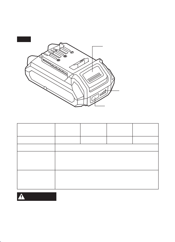
GET TO KNOW YOUR BATTERY
PWR
CORE
20
TM
Lithium Battery Pack
Fig. 1
Battery-Release Button
Fuel Gauge
Battery-Indicator Button
SPECIFICATIONS
Model No. SKIL
BY519701
SKIL
BY519703
SKIL
BY519601
SKIL
BY519603
Battery Capacity 2Ah 2.5Ah 4Ah 5Ah
Battery Voltage 20 V
Recommended
Charging
Temperature
41°F(5°C) ~ 104°F(40°C)
Recommended
Storage
Temperature
32°F (0°C) ~104°F (40°C)
WARNING
The batteries listed above can only be
charged with SKIL SC535801, QC536001
chargers.
Note:
Use of chargers or battery packs not sold by SKIL will
void the warranty.
14
OPERATING INSTRUCTIONS
WARNING
To reduce the risk of re, personal injury,
and product damage due to a short
circuit, never immerse your charger or battery pack in uid
or allow a uid to ow inside them.
Corrosive or conductive
uids, such as seawater, certain industrial chemicals, and
bleach or bleach-containing products, etc., can cause a short
circuit.
When to Charge the Battery Pack
It is not necessary to run down the battery pack charge before
recharging. The Lithium-Ion battery can be charged at any time
and will not develop a “memory” when charged after only a partial
discharge.
Remove the battery pack from the tool when it is convenient for you
and your job.
“Top off” the battery pack charge by charging it for a time before
starting a big job or use for long period of use.
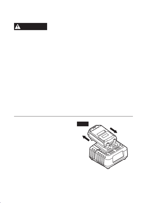
How to Charge the Battery
Pack
NOTICE:
The Lithium battery pack
is shipped partially charged.
Before using it the rst time, fully
charge the battery pack.
a. Charge the battery pack with
the correct charger.
b. Connect the charger to a power
supply. The red Defect Indicator
and green Charging Indicator will shine for one second and then
go out, indicating that the charger self-inspection is completed.
Fig. 2
Attach
Deatch

15
c. Align the raised ribs of the battery pack with the slot in the
charger.
d. Insert the battery pack into the charger (Fig. 2).
e. The charger will communicate with the battery pack to evaluate
the condition of the battery pack.
f. The charger will charge the battery pack automatically.
Please refer to the charger manual for detailed charging operation.
NOTICE:
If the battery pack cannot accept a charge, the contacts
of the charger or battery pack may be contaminated. Clean the
contacts of the charger or battery pack (e. g., by inserting and
removing the battery several times or by cleaning with a cotton
swab and alcohol), replace a new charger or replace the battery
pack, as required.
Defective Battery Pack
If the charger detects a problem, the red Defect Indicator will begin
ashing. Remove and re-insert the battery pack in the charger. If
the Defect Indicator ashes a second time, try charging a different
battery pack.
a. If a different battery pack charges normally, have the rst
defective battery pack serviced by an Authorized SKIL Service
Station.
b. If a different battery pack also indicates “defective,” the charger
may be defective. Have the charger serviced by an Authorized
SKIL Service Station.
16
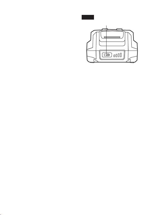
Fuel Gauge (Fig.3)
The four LEDs on the front
housing of the battery indicate
the current battery capacity when
the battery-indicator button is
depressed.
If the rst LED on the Fuel Gauge
ashes slowly when the battery-
indicator button is depressed,
this indicates a low charge level.
Recharge the battery.
If the rst and third LED on the fuel gauge rapidly ash green when
the battery-indicator button is depressed, this indicates that the
battery is too hot. Cool the battery pack under air ow.
To Attach/Detach Battery Pack
Follow the instructions in the Owner’s Manual for the individual SKIL
tool.
Fig. 3
Battery-Indicator
Button

17
MAINTENANCE
Service
WARNING
Preventive maintenance performed by
unauthorized personnel may result in
misplacing of internal wires and components which could
cause serious hazard.
We recommend that all tool service be
performed by a SKIL Factory Service Center or Authorized SKIL
Service Station.
General Maintenance
WARNING
When servicing, use only identical re-
placement parts. Use of any other parts
could create a hazard or cause product damage.
Periodically inspect the entire product for damaged, missing, or
loose parts such as screws, nuts, bolts, caps, etc. Tighten securely
all fasteners and caps and do not operate this product until all
missing or damaged parts are replaced. Please contact customer
service or an authorized service center for assistance.
WARNING
To avoid serious personal injury, always
remove the battery pack from the char-
ger/tool when cleaning or performing any maintenance.
Cleaning
WARNING
The tool may be cleaned most effectively with
compressed dry air.
Always wear safety
goggles when cleaning tools with compressed air.
Do not
attempt to clean by inserting pointed objects through openings.
WARNING
Certain cleaning agents and solvents
damage plastic parts.
Some of these are:
gasoline, carbon tetrachloride, chlorinated cleaning solvents,
ammonia and household detergents that contain ammonia.

18
Storage
Store the tool indoors in a place that is inaccessible to children.
Keep away from corrosive agents.
BATTERY CARE
WARNING
When batteries are not in tool or charger,
keep them away from metal objects.
For
example, to protect terminals from shorting DO NOT place batteries
in a tool box or pocket with nails, screws, keys, etc. Fire or injury
may result.
DO NOT PUT BATTERIES INTO FIRE OR EXPOSE TO HIGH
HEAT.
They may explode.

19
BATTERY DISPOSAL
WARNING
Do not attempt to disassemble the battery
or remove any component projecting from
the battery terminals.
Fire or injury may result. Prior to disposal,
protect exposed terminals with heavy insulating tape to prevent
shorting.
Lithium-Ion Batteries:
If equipped with a lithium-ion battery,
the battery must be collected, recycled or disposed of in an
environmentally sound manner.
The EPA certied RBRC Battery Recycling
Seal on the lithium-ion (Li-ion) battery
indicates Chervon North America is voluntarily
participating in an industry program to collect
and recycle these batteries at the end of their
useful life, when taken out of service in the
United States or Canada. The RBRC program
provides a convenient alterative to placing used
Li-ion batteries into the trash or the municipal
waste stream, which may be illegal in your
area.
Please call 1-800-8-BATTERY for information
on Li-ion battery recycling and disposal bans/
restrictions in your area, or return your batteries
to a SKIL Service Center for recycling. Chervon
North America’s involvement in this program
is part of our commitment to preserving our
environment and conserving our natural
resources.

20
LIMITED WARRANTY OF SKIL CONSUMER TOOLS
2 YEAR LIMITED WARRANTY- LEGAL
Chervon North America, Inc. ("Seller") warrants to the original
purchaser only, that all SKIL consumer BATTERIES AND CHARGERS
will be free from defects in material or workmanship for a period of two
years from date of purchase.
Product registration can be completed online at www.Registermyskil.
com. Original purchasers should also retain their receipt as proof of
purchase.
Notwithstanding the foregoing, if a SKIL consumer portable power
tool is used for industrial, professional or commercial purposes, the
foregoing warranty will apply for a duration of ninety days, regardless of
registration.
SELLER’S SOLE OBLIGATION AND YOUR EXCLUSIVE REMEDY
under this Limited Warranty and, to the extent permitted by law, any
warranty or condition implied by law, shall be the repair or replacement
of parts, without charge, which are defective in material or workmanship
and which have not been misused, carelessly handled, or repaired
by persons other than Seller or Authorized Service Station. To make
a claim under this Limited Warranty, you must return the complete
product, transportation prepaid, to any SKIL Factory Service Center or
Authorized Service Station. For Authorized SKIL Power Tool Service
Stations, please visit www.Registermyskil.com or call 1-877-SKIL-999
(1-877-754-5999).
THIS LIMITED WARRANTY DOES NOT APPLY TO ACCESSORY
ITEMS SUCH AS CIRCULAR SAW BLADES, DRILL BITS.
ANY IMPLIED WARRANTIES APPLICABLE TO A PRODUCT SHALL
BE LIMITED IN DURATION EQUAL TO THE DURATION OF THE
EXPRESS WARRANTIES APPLICABLE TO SUCH PRODUCT, AS
SET FORTH IN THE FIRST PARAGRAPH ABOVE. SOME STATES
IN THE U.S., SOME CANADIAN PROVINCES DO NOT ALLOW
LIMITATIONS ON HOW LONG AN IMPLIED WARRANTY LASTS,
SO THE ABOVE LIMITATION MAY NOT APPLY TO YOU.

21
IN NO EVENT SHALL SELLER BE LIABLE FOR ANY INCIDENTAL
OR CONSEQUENTIAL DAMAGES (INCLUDING BUT NOT LIMITED
TO LIABILITY FOR LOSS OF PROFITS) ARISING FROM THE SALE
OR USE OF THIS PRODUCT. SOME STATES IN THE U.S. AND
SOME CANADIAN PROVINCES DO NOT ALLOW THE EXCLUSION
OR LIMITATION OF INCIDENTAL OR CONSEQUENTIAL
DAMAGES, SO THE ABOVE LIMITATION OR EXCLUSION MAY
NOT APPLY TO YOU.
THIS LIMITED WARRANTY GIVES YOU SPECIFIC LEGAL RIGHTS,
AND YOU MAY ALSO HAVE OTHER RIGHTS WHICH VARY FROM
STATE TO STATE IN THE U.S., PROVINCE TO PROVINCE IN
CANADA AND FROM COUNTRY TO COUNTRY.
THIS LIMITED WARRANTY APPLIES ONLY TO PRODUCTS SOLD
WITHIN THE UNITED STATES OF AMERICA, CANADA AND
THE COMMONWEALTH OF PUERTO RICO. FOR WARRANTY
COVERAGE WITHIN OTHER COUNTRIES, CONTACT YOUR
LOCAL SKIL DEALER OR IMPORTER.
© Chervon North America, 1203 E. Warrenville Rd, Naperville, IL 60563.
01/19
1-877-SKIL-999
OR
www.skil.com
For Customer Service
Pour le service à la clientèle
Servicio al cliente
WARNING: To reduce the risk of injury, the user must read and understand the
Owner’s Manual before using this product. Save these instructions for future reference.
Owner’s Manual
20V PWR Assist USB Charging Adapter
Model: AD592301

2
TABLE OF CONTENTS
Safety Instructions ...............................3-5
Symbols .......................................6-10
Get to Know Your USB Charging Adapter ..........11-12
Specications ....................................11
Operating Instructions ..........................13-15
Maintenance ...................................16-17
Troubleshooting ..................................17
Limited Warranty of SKIL Cordless Tool ............18-19

3
SAFETY INSTRUCTIONS
IMPORTANT SAFETY INSTRUCTIONS
WARNING
Read all safety warnings and instructions.
Failure to follow the warnings and instructions
may result in electric shock, re and/or serious injury.
Save these instructions - This operator’s manual contains
important safety and operating instructions for the 20V
USB Charging Adapter. Before using the adapter, read this
operator’s manual, your battery pack and charger operator’s
manual, and all labels on the battery pack, charger and adapter.
Work area safety
Avoid dangerous environments. Do not use in rain, snow,
damp or wet locations. Do not use in the presence of explosive
atmospheres (gaseous fumes, dust or ammable materials)
because sparks may be generated when inserting or removing
battery pack, possibly causing re.
Electrical safety
Do not use an extension cord with the adapter. Using an
extension cord could result in the risk of re and electrical shock.
Personal safety
Follow adapter manufacturers’ instructions regarding operation
and power. Use of the adapter different from those intended could
result in a hazardous situation.
Use the correct adapter for the application.
Stay alert, watch what you are doing and use common sense
when operating adapter. Do not use while you are tired or
under the inuence of drugs, alcohol or medication. A moment
of inattention may result in serious personal injury.

4
Use and care
Remove the battery pack or any other devices from the adapter
before storing. Such preventive safety measures reduce the risk of
starting the adapter accidentally.
Prevent unintentional starting. Ensure the switch is in the
off-position before connecting to battery pack, picking up or carrying
the adapter. Carrying the adapter with your nger on the switch or
energizing adapter that have the switch on invites accidents.
Store idle adapter and battery pack out of the reach of children
and do not allow persons unfamiliar with the adapter, battery
pack or these instructions to operate them. Adapters and battery
packs are dangerous in the hands of untrained users.
Disconnect the battery pack from the adapter before making
any adjustments, changing accessories, maintenance, or
storing adapter.
Check for misalignment, breakage of parts and any other
condition that may affect the adapter operation. If damaged,
have the adapters repaired before use. Many accidents are
caused by poorly maintained adapters.
Use the adapter in accordance with these instructions, taking
into account the working conditions and the work to be
performed. Use of the adapter for operations different from those
intended could result in a hazardous situation.
Keep adapter and battery pack away from other metal objects
like paper clips, coins, keys, nails, screws, or other small
metal objects that can make a connection from one terminal to
another. Shorting the terminals together may cause burns or a re.
Under abusive conditions, liquid may be ejected from the
battery; avoid contact. If contact accidentally occurs, ush with
water. If liquid contacts eyes, additionally seek medical help. Liquid
ejected from the battery may cause irritation or burns.
Do not use a battery pack or adapter that is damaged or
modied. Damaged or modied batteries may exhibit unpredictable
behavior resulting in re, explosion or risk of injury.

5
Battery use and care
Adapter is rated for 20 V DC only. Use only appropriate battery
packs as in adapter the specication mentioned. Use of any other
battery packs may create a risk of injury and re.
Recharge only with the charger specied by the manufacturer.
A charger that is suitable for one type of battery pack may create a
risk of re when used with another battery pack.
To reduce the risk of electric shock, always remove battery
pack before cleaning or maintenance.
Do not expose a battery pack or adapter to re or excessive
temperature. Exposure to re or temperature above 265°F (130°C)
may cause explosion.
Follow all charging instructions and do not charge the battery
pack or adapter outside of the temperature range specied in the
instructions. Charging improperly or at temperatures outside of the
specied range may damage the battery and increase the risk of re.
Service
Do not disassemble. Incorrect reassembly may result in the risk of
electric shock or re. If it is damaged, take it to a specied service
facility.
Store in a cool, dry place. Do not store where temperatures may
exceed 104°F (40°C) such as in direct sunlight, a vehicle or metal
building during the summer.
Maintain labels and nameplates. These carry important
information. If unreadable or missing, contact a specied service
facility for a free replacement.
Have servicing performed by a qualied repair person using
only identical replacement parts. This will ensure that the safety
of the product is maintained.
Do not modify or attempt to repair the adapter or the battery
pack except as indicated in the instructions for use and care.
SAVE THESE INSTRUCTIONS
6
SYMBOLS
Safety Symbols
The purpose of safety symbols is to attract your attention to
possible dangers. The safety symbols and the explanations with
them deserve your careful attention and understanding. The
symbol warnings do not, by themselves, eliminate any danger.
The instructions and warnings they give are no substitutes for
proper a cident prevention measures.
WARNING
Be sure to read and understand all safety
instructions in this Owner’s Manual,
including all safety alert symbols such as “DANGER,”
“WARNING,” and “CAUTION” before using this tool. Failure to
following all instructions listed below may result in electric
shock, re, and/or serious personal injury.
The denitions below describe the level of severity for each
signal word. Please read the manual and pay attention to
these symbols.
This is the safety alert symbol. It
is used to alert you to potential
personal injury hazards. Obey all
safety messages that follow this
symbol to avoid possible injury or
death.
DANGER
DANGER indicates a hazardous
situation which, if not avoided, will
result in death or serious injury.
WARNING
WARNING indicates a hazardous
situation which, if not avoided,
could result in death or serious
injury.
7
CAUTION
CAUTION, used with the safety
alert symbol, indicates a hazardous
situation which, if not avoided, will
result in minor or moderate injury.
Damage Prevention and Information Messages
These inform the user of important information and/or instructions
that could lead to equipment or other property damage if they are
not followed. Each message is preceded by the word “NOTICE”, as
in the example below:
NOTICE: Equipment and/or property damage may result if these
instructions are not followed
WARNING
The operation of any power
tools can result in foreign
objects being thrown into your eyes, which can
result in severe eye damage. Before beginning
power tool operation, always wear safety goggles
or safety glasses with side shields and a full face
shield when needed. We recommend a Wide
Vision Safety Mask for use over eyeglasses or
standard safety glasses with side shields. Always
use eye protection which is marked to comply with
ANSI Z87.1.

8
SYMBOLS (CONTINUED)
IMPORTANT: Some of the following symbols may be used on
your tool. Please study them and learn their meaning. Proper
interpretation of these symbols will allow you to operate the tool
better and more safely.
Symbol Name Designation/Explanation
V Volts Voltage (potential)
A Amperes Current
Hz Hertz
Frequency (cycles per
second)
W Watt Power
kg Kilograms Weight
min Minutes Time
s Seconds Time
Wh Watt-hours Battery capacity
Ah Ampere-Hours Battery capacity
Alternating
current
Type or a characteristic of
current
Direct current
Type or a characteristic of
current
Alternating or
direct current
Type or a characteristic of
current
Class II
construction
Designates Double Insulated
Construction tools.
9
Symbol Name Designation/Explanation
Earthing terminal Grounding terminal
Li-ion RBRC
seal
Designates Li-ion battery
recycling program
Ni-Cad RBRC
seal
Designates Ni-Cad battery
recycling program
Read manual
symbol
Alerts user to read manual
Wear eye
protection
symbol
Alerts user to wear eye
protection
SYMBOLS (CERTIFICATION INFORMATION)
IMPORTANT: Some of the following symbols for certication
information may be used on your tool. Please study them and learn
their meaning. Proper interpretation of these symbols will allow you
to operate the tool better and more safely.
Symbol Designation/Explanation
This symbol designates that this tool is
listed by Underwriters Laboratories.
This symbol designates that this tool is
recognized by Underwriters Laboratories.
10
Symbol Designation/Explanation
This symbol designates that this tool is
listed by Underwriters Laboratories, to
United States and Canadian Standards.
This symbol designates that this tool
is listed by the Canadian Standards
Association.
This symbol designates that this tool
is listed by the Canadian Standards
Association, to United States and Canadian
Standards.
This symbol designates that this tool is
listed by the Intertek Testing Services, to
United States and Canadian Standards.
This symbol designates that this tool
complies to NOM Mexican Standards.
BC
This symbol designates that this tool is
listed by the California Energy Commission.
11
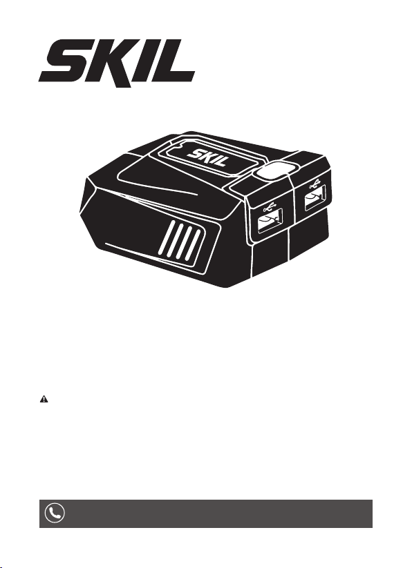
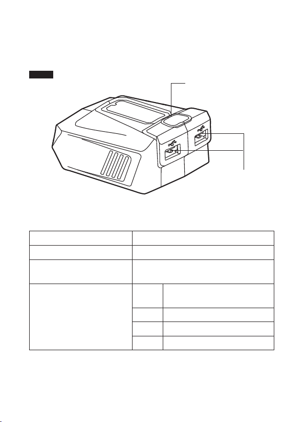
GET TO KNOW YOUR USB CHARGING ADAPTER
SKIL PWRCORE 20
TM
USB Charging Adapter
ON/OFF Button
(Indicator)
Fig. 1
SPECIFICATIONS
Rated input 20V d.c.
Output voltage 5.1V d.c.
Output current
Max. 2.1 A (each port)
Max. 3.6 A (in total)
Battery Pack Compatibility
2.0Ah
SKIL BY519701
、
SKIL BY519702
2.5Ah SKIL BY519703
4.0Ah SKIL BY519601
5.0Ah SKIL BY519603
USB Ports

12
Charger Compatibility SKIL SC535801
Recommended Charging
Temperature
41°F(5°C) ~ 104°F(40°C)
Recommended Adapter
and Battery Pack Storage
Temperature
32°F (0°C)~104°F (40°C)
WARNING
This USB charging adapter must be used
only with the battery packs and charger
listed above.
NOTICE:
Please refer to the battery and charger manuals for
detailed operating information.
13
OPERATING INSTRUCTIONS
WARNING
To reduce the risk of re, personal injury,
and product damage due to a short
circuit, never immerse your tool or battery pack in uid or
allow a uid to ow inside them. Corrosive or conductive
uids, such as seawater, certain industrial chemicals, and bleach
or bleach-containing products, etc, can cause a short circuit.
WARNING
If any parts are damaged or missing, do
not operate this product until the parts
are replaced. Use of this product with damaged or missing
parts could result in serious personal injury.
WARNING
Do not attempt to modify this product or
create accessories not recommended for
use with this product. Any such alteration or modication is
misuse and could result in a hazardous condition leading to
possible serious injury.
WARNING
Do not use USB charging adaptor in
explosive atmospheres, such as in the
presence of ammable liquids, gases or dust.
CAUTION
This USB charging adapter is used to
charge cell phone, tablet, e-book and
other USB device.
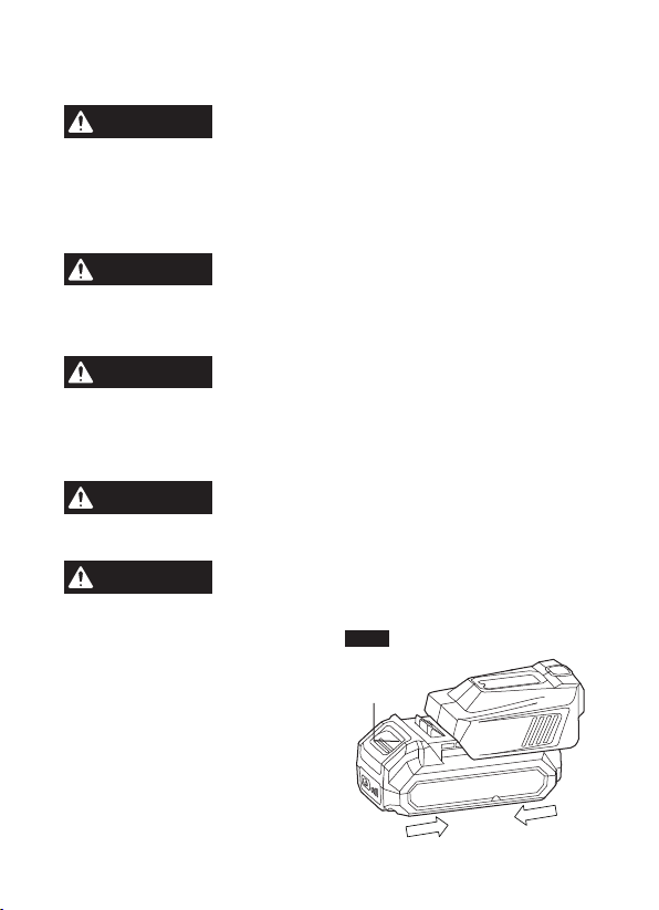
To Attach/Detach Battery
Pack (Fig. 2)
a. To attach the battery pack:
Align the raised rib on the
battery pack with the grooves of
the adapter, and then slide the
battery pack onto the adapter.
Battery-
Release
Button
Attach
Fig. 2
Detach
14
b. To detach the battery pack:
Depress the battery-release button, located on the front of the
battery pack, to release the battery pack. Pull the battery pack out
and remove it from the adapter.
NOTICE: When assembling the battery pack to the adapter, be sure
that the raised rib on the battery pack aligns with the groove inside
the adapter and that the latches snap into place properly. Improper
attachment of the battery pack can cause damage to internal
components.
NOTICE: Battery products are always in operating condition.
Therefore, always remove the adapter from the battery when it is
not in use.
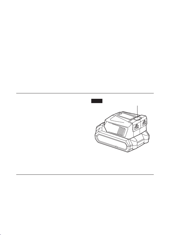
ON/OFF Button (Fig. 3)
a. To turn on the adapter, press the
ON/OFF button. The indicator
will shine green, indicating that
the adapter is active.
b. To turn off the adapter, press the
ON/ OFF button. The indicator
will be off to indicate that the
adapter is deactivated
NOTICE: When the adapter has
not been in use for approximately 3 hours, it will automatically turn
off and the green light will be off.
ON/OFF Button
(Indicator)
Fig. 3
15
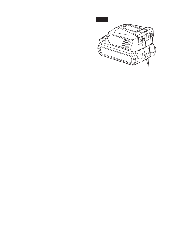
Using with a USB Device
(Fig. 4)
When a battery pack is installed,
place it on a surface to avoid
damage to the adapter during
operation.
a. Insert a battery pack into the
adapter.
b. Plug a USB cable (not included)
into one of the USB ports in the
adapter and plug the other end of the cable into your device.
c. Press the ON/OFF button to begin charging the USB device.
d. The USB device will fully charge.
e. After charging is completed, if left connected with the adapter,
it will automatically shut off after approximately 3 hours, and the
charging process will stop.
f. To reactivate the adapter, press the ON/OFF button.
g. When not using or after charging, remove the USB cable and
remove the adapter from the battery.
NOTICE:
•
The maximum current draw is 2.1A for each port and 3.6A total for
both ports.
•
If the device draws more than the rated output of the ports, the
adapter will shut off to protect the battery pack. To reactivate the
adapter, remove the device and press the ON/OFF button.
•
Charging time is dependent upon the device.
•
The adapter may warm with several continuous cycles; this is part
of its normal operation. Always use the adapter in a well-ventilated
area.
USB Ports
Fig. 4

16
MAINTENANCE
WARNING
To avoid serious personal injury, always
remove the battery pack from the tool when
cleaning or performing any maintenance.
Service
WARNING
Preventive maintenance performed by
unauthorized personnel may result in
misplacing of internal wires and components which could
cause serious hazard
.
We recommend that all tool service be
performed by a SKIL Factory Service Center or Authorized SKIL
Service Station
.
General Maintenance
WARNING
When servicing, use only identical
replacement parts. Use of any other parts
could create a hazard or cause product damage
.
Periodically inspect the entire product for damaged, missing, or
loose parts such as screws, nuts, bolts, caps, etc. Tighten securely
all fasteners and caps and do not operate this product until all
missing or damaged parts are replaced. Please contact customer
service or an authorized service center for assistance.
Cleaning
WARNING
The tool may be cleaned most effectively
with a soft, dry cloth. Keep the power ports
clean, dry and free of oil or grease. Do not attempt to clean by
inserting pointed objects through openings.
WARNING
Certain cleaning agents and solvents
damage plastic parts
.
Some of these are:
gasoline, carbon tetrachloride, chlorinated cleaning solvents,
ammonia and house hold detergents that contain ammonia
.

17
Storage
Store the tool indoors in a place that is inaccessible to children.
Keep away from corrosive agents.
TROUBLESHOOTING
Problem Cause Remedy
The USB
charging
adapter does
not work
.
1. Low battery
capacity.
2. The device draws
more than the rated
output of the ports.
1. Charge the battery.
2. Remove the device
and turn the adapter on
again.

18
LIMITED WARRANTY OF SKIL CONSUMER TOOLS
5 YEAR LIMITED WARRANTY- LEGAL
Chervon North America, Inc. ("Seller") warrants to the original
purchaser only, that all SKIL consumer TOOLS will be free from
defects in material or workmanship for a period of ve years
from date of purchase, if original purchaser registers the product
within 30 days from purchase. BATTERIES AND CHARGERS are
warranted for 2 years. Product registration can be completed online
at www.Registermyskil.com. Original purchasers should also retain
their receipt as proof of purchase. THE FIVE-YEAR WARRANTY
PERIOD FOR TOOLS IS CONDITIONED ON REGISTRATION
OF THE PRODUCT WITHIN 30 DAYS OF PURCHASE. If original
purchasers do not register their product timely, the foregoing
limited warranty will apply for a duration of three years for tools.
All batteries and chargers will remain under the two-year limited
warranty.
Notwithstanding the foregoing, if a SKIL consumer tool is used
for industrial, professional or commercial purposes, the foregoing
warranty will apply for a duration of ninety days, regardless of
registration.
SELLER’S SOLE OBLIGATION AND YOUR EXCLUSIVE REMEDY
under this Limited Warranty and, to the extent permitted by law,
any warranty or condition implied by law, shall be the repair or
replacement of parts, without charge, which are defective in material
or workmanship and which have not been misused, carelessly
handled, or repaired by persons other than Seller or Authorized
Service Station. To make a claim under this Limited Warranty, you
must return the complete product, transportation prepaid, to any
SKIL Factory Service Center or Authorized Service Station. For
Authorized SKIL Power Tool Service Stations, please visit www.
Registermyskil.com or call 1-877-SKIL-999 (1-877-754-5999).
THIS LIMITED WARRANTY DOES NOT APPLY TO ACCESSORY
ITEMS SUCH AS CIRCULAR SAW BLADES, DRILL BITS,

19
ROUTER BITS, JIGSAW BLADES, SANDING BELTS, GRINDING
WHEELS AND OTHER RELATED ITEMS.
ANY IMPLIED WARRANTIES APPLICABLE TO A PRODUCT
SHALL BE LIMITED IN DURATION EQUAL TO THE DURATION
OF THE EXPRESS WARRANTIES APPLICABLE TO SUCH
PRODUCT, AS SET FORTH IN THE FIRST PARAGRAPH ABOVE.
SOME STATES IN THE U.S., SOME CANADIAN PROVINCES
DO NOT ALLOW LIMITATIONS ON HOW LONG AN IMPLIED
WARRANTY LASTS, SO THE ABOVE LIMITATION MAY NOT
APPLY TO YOU.
IN NO EVENT SHALL SELLER BE LIABLE FOR ANY INCIDENTAL
OR CONSEQUENTIAL DAMAGES (INCLUDING BUT NOT
LIMITED TO LIABILITY FOR LOSS OF PROFITS) ARISING
FROM THE SALE OR USE OF THIS PRODUCT. SOME STATES
IN THE U.S. AND SOME CANADIAN PROVINCES DO NOT
ALLOW THE EXCLUSION OR LIMITATION OF INCIDENTAL OR
CONSEQUENTIAL DAMAGES, SO THE ABOVE LIMITATION OR
EXCLUSION MAY NOT APPLY TO YOU.
THIS LIMITED WARRANTY GIVES YOU SPECIFIC LEGAL
RIGHTS, AND YOU MAY ALSO HAVE OTHER RIGHTS WHICH
VARY FROM STATE TO STATE IN THE U.S., PROVINCE TO
PROVINCE IN CANADA AND FROM COUNTRY TO COUNTRY.
THIS LIMITED WARRANTY APPLIES ONLY TO PRODUCTS
SOLD WITHIN THE UNITED STATES OF AMERICA, CANADA
AND THE COMMONWEALTH OF PUERTO RICO. FOR
WARRANTY COVERAGE WITHIN OTHER COUNTRIES,
CONTACT YOUR LOCAL SKIL DEALER OR IMPORTER.
© Chervon North America, 1203 E. Warrenville Rd, Naperville, IL 60563.
09/18
WARNING: To reduce the risk of injury, the user must read and understand the
Owner’s Manual before using this product. Save these instructions for future reference.
Owner’s Manual
For Customer Service
Pour le service à la clientèle
Servicio al cliente
1-877-SKIL-999
OR
www.skil.com
WARNING: To reduce the risk of injury, the user must read and understand the
Owner’s Manual before using this product. Save these instructions for future reference.
Charger
Model: QC536001

2
TABLE OF CONTENTS
Charger Safety Instructions . ....................................3-4
Extension Cords ................................................4
FCC Caution ....................................................5
Symbols .....................................................6-9
Get to Know Your Charger .......................................10
Specications .................................................10
Important Charging Notes .......................................11
Operating Instructions .......................................12-14
Maintenance ...................................................15
Troubleshooting ...............................................15
Limited Warranty of SKIL Charger .................................16

3
IMPORTANT SAFETY INSTRUCTIONS - SAVE THESE
INSTRUCTIONS
DANGER
TO REDUCE THE RISK OF FIRE OR ELECTRIC SHOCK, CAREFULLY
FOLLOW THESE INSTRUCTIONS.
CHARGER SAFETY INSTRUCTIONS
Save these instructions.
This manual contains important safety and operating instructions
for battery charger model QC536001.
Before using battery charger, read all instructions and cautionary markings on battery
charger, battery and product using battery.
CAUTION
To reduce risk of injury, charge only SKIL rechargeable batteries
listed in the manual.
Other types of batteries may burst causing personal
injury and damage.
Charge battery pack within the required temperature range. Store charger and battery
pack in locations where temperature is within the recommended storage temperature
range.
This is important to prevent serious damage to the battery cells.
Do not recharge battery in damp or wet environment. Do not expose charger to rain or
snow.
Water entering battery charger may result in electric shock or re.
Battery leakage may occur under extreme usage or temperature conditions. Avoid
contact with skin and eyes.
The battery liquid is caustic and could cause chemical burns
to tissues. If liquid comes in contact with skin, wash quickly with soap and water. If the liquid
contacts your eyes, ush them with water for a minimum of 10 minutes and seek medical
attention.
Place charger on at nonammable surfaces and away from ammable materials when
recharging battery pack.
Carpeting and other heat insulating surfaces block proper air
circulation which may cause overheating of the charger and battery pack. If smoke or melting
of the charger or battery pack is observed, unplug the charger immediately and do not use the
battery pack or charger. Contact customer service immediately.
Keep the cord and charger from heat to prevent damage to housing or internal parts.
Do not allow gasoline, oils, petroleum-based products, etc. to come in contact with
plastic parts.
These materials contain chemicals that can damage, weaken, or destroy
plastic.
Make sure cord is located so that it will not be stepped on, tripped over, or otherwise
subjected to damage or stress.
Damaged plug and cord may result in electric shock or re.
Disconnect the charger by pulling the plug rather than the cord. Do not operate charger
with damaged cord or plug; have them replaced immediately.
Damaged plug or cord may
result in electric shock or re.
Do not insert battery pack in charger if battery pack case is cracked.
Using damaged
battery pack may result in electric shock or re.
Do not disassemble charger or operate the charger if it has received a sharp blow, been
dropped or otherwise damaged in anyway.
Incorrect reassembly or damage may result in
electric shock or re.
Before each use, check the battery charger, cable and plug. If damage is detected,
do not use the battery charger. Never open the battery charger yourself, take it to a
SKIL Factory Service Center, or qualied serviceman only using original spare parts.
Incorrect reassembly may result in electric shock or re.
Do not touch the uninsulated portion of output connector or uninsulated battery
terminal.
There is a risk of electric shock.
4
Do not use attachment not recommended or sold by SKIL.
Using attachments not
recommended may result in electric shock or re.
Do not store battery pack in charger.
Battery pack stored in charger over a long period of
time could lead to battery pack damage and re.
Unplug charger from outlet before storage, attempting any maintenance or cleaning.
Such preventive safety measures reduce the risk of electric shock or re.
Keep the battery charger clean by blowing compressed air on charger vents and wiping
the charger housing with a damp cloth.
Contamination may result in electric shock or re.
Replace battery pack if a substantial drop in operating time per charge is observed.
Battery pack may be nearing the end of its life.
To reduce the risk of injury, close supervision is necessary when an appliance is used
near children.
Do not use outdoors.
EXTENSION CORDS
WARNING
AN EXTENSION CORD SHOULD NOT BE USED UNLESS ABSOLUTE-
LY NECESSARY.
Use of improper extension cord could result in risk of re
and electrical shock. If an extension cord is used, make sure:
a. The pins on plug of extension cord are the same number, size, and shape as those of plug
on charger.
b. The extension cord is properly wired and in good electrical condition.
c. The wire size is large enough for AC ampere rating of charger as specied below:
Length of Cord (Feet) 25’ 50’ 100’ 150’
Size of Cord (AWG) 18 16 16 14
Extension Cord Chart for 220/240 Volt Tools:
0.75mm2 CORD 50 Meters
1.0mm2 CORD 75 Meters
d. An extension cord is a temporary solution. Move the charger to a standard receptacle as
soon as the job has been completed.

5
FCC CAUTION
1. This device complies with Part 15 of the FCC Rules. Operation is subject to the following
two conditions:
(1) This device may not cause harmful interference.
(2) This device must accept any interference received, including interference that may cause
undesired operation.
2. Changes or modications not expressly approved by the party responsible for compliance
could void the user’s authority to operate the equipment.
NOTE:
This equipment has been tested and found to comply with the limits for a Class B
digital device, pursuant to Part 15 of the FCC Rules. These limits are designed to provide
reasonable protection against harmful interference in a residential installation. This equipment
generates, uses, and can radiate radio frequency energy and, if not installed and used in
accordance with the instructions, may cause harmful interference to radio communications.
However, there is no guarantee that interference will not occur in a particular installation. If
this equipment does cause harmful interference to radio or television reception, which can be
determined by turning the equipment off and on, the user is encouraged to try to correct the
interference by one or more of the following measures:
•
Reorient or relocate the receiving antenna.
•
Increase the separation between the equipment and receiver.
•
Connect the equipment into an outlet on a circuit different from that to which the receiver is
connected.
•
Consult the dealer or an experienced radio/TV technician for help.
DANGER
People with electronic devices, such as pacemakers, should consult
their physician(s) before using this product. Operation of electrical
equipment in close proximity to a heart pacemaker could cause interference or failure
of the pacemaker.
6
SYMBOLS
Safety Symbols
The purpose of safety symbols is to attract your attention to possible dangers. The safety
symbols and the explanations with them deserve your careful attention and understanding.
The symbol warnings do not, by themselves, eliminate any danger. The instructions and
warnings they give are no substitutes for proper accident prevention measures.
WARNING
Be sure to read and understand all safety instructions in this Owner's
Manual, including all safety alert symbols such as “
DANGER
,”
“
WARNING
,” and “
CAUTION
” before using this tool. Failure to following all instructions listed
below may result in electric shock, re, and/or serious personal injury.
The denitions below describe the level of severity for each signal word. Please read the manual
and pay attention to these symbols.
This is the safety alert symbol. It is used to alert you to potential
personal injury hazards. Obey all safety messages that follow this
symbol to avoid possible injury or death.
DANGER
DANGER indicates a hazardous situation which, if not avoided, will
result in death or serious injury.
WARNING
WARNING indicates a hazardous situation which, if not avoided, could
result in death or serious injury.
CAUTION
CAUTION, used with the safety alert symbol, indicates a hazardous
situation which, if not avoided, will result in minor or moderate injury.
Damage Prevention and Information Messages
These inform the user of important information and/or instructions that could lead to equipment
or other property damage if they are not followed. Each message is preceded by the word
“NOTICE”, as in the example below:
NOTICE:
Equipment and/or property damage may result if these instructions are not followed.
WARNING
The operation of any power tools can result in
foreign
objects being thrown into your eyes, which can result
in severe eye damage. Before beginning power tool operation, always
wear safety goggles or safety glasses with side shields and a full face
shield when needed. We recommend a Wide Vision Safety Mask for use
over eyeglasses or standard safety glasses with side shields. Always use
eye protection which is marked to comply with ANSI Z87.1.

7
SYMBOLS (CONTINUED)
IMPORTANT:
Some of the following symbols may be used on your tool. Please study them
and learn their meaning. Proper interpretation of these symbols will allow you to operate the
tool better and more safely.
Symbol Name Designation/Explanation
V Volts Voltage (potential)
A Amperes Current
Hz Hertz Frequency (cycles per second)
W Watt Power
kg Kilograms Weight
min Minutes Time
s Seconds Time
Wh Watt-hours Battery capacity
Ah Ampere-Hours Battery capacity
Ø Diameter Size of drill bits, grinding wheels, etc.
n
0
No load speed Rotational speed, at no load
n Rated speed Maximum attainable speed
…/min
Revolutions or reciprocation
per minute
Revolutions, strokes, surface speed,
orbits, etc. per minute
0 Off position Zero speed, zero torque...
1,2,3,…
I,II,III,
Selector settings
Speed, torque or position settings. Higher
number means greater speed
Innitely variable selector
with off
Speed is increasing from 0 setting
Arrow Action in the direction of arrow
Alternating current Type or a characteristic of current
Direct current Type or a characteristic of current
Alternating or direct current Type or a characteristic of current
Class II tool
Designates Double Insulated Construction
tools.
Earthing terminal Grounding terminal
Li-ion RBRC seal
Designates Li-ion battery recycling
program
Ni-Cad RBRC seal
Designates Ni-Cad battery recycling
program

8
Symbol Name Designation/Explanation
Read manual symbol Alerts user to read manual
Wear eye protection symbol
Always wear safety goggles or safety
glasses with side shields and a full face
shield when operating this product.
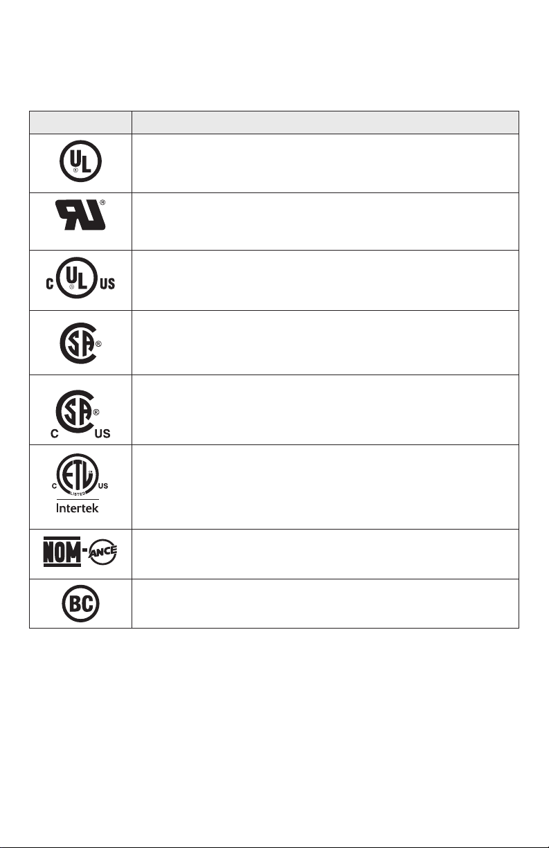
9
SYMBOLS (CERTIFICATION INFORMATION)
IMPORTANT:
Some of the following symbols for certication information may be used on your
tool. Please study them and learn their meaning. Proper interpretation of these symbols will
allow you to operate the tool better and more safely.
Symbol Designation/Explanation
This symbol designates that this tool is listed by Underwriters Laboratories.
This symbol designates that this tool is recognized by Underwriters
Laboratories.
This symbol designates that this tool is listed by Underwriters
Laboratories, to United States and Canadian Standards.
This symbol designates that this tool is listed by the Canadian
Standards Association.
This symbol designates that this tool is listed by the Canadian
Standards Association, to United States and Canadian Standards.
This symbol designates that this tool is listed by the Intertek Testing
Services, to United States and Canadian Standards.
This symbol designates that this tool complies to NOM Mexican
Standards.
This symbol designates that this tool is listed by the California Energy
Commission.
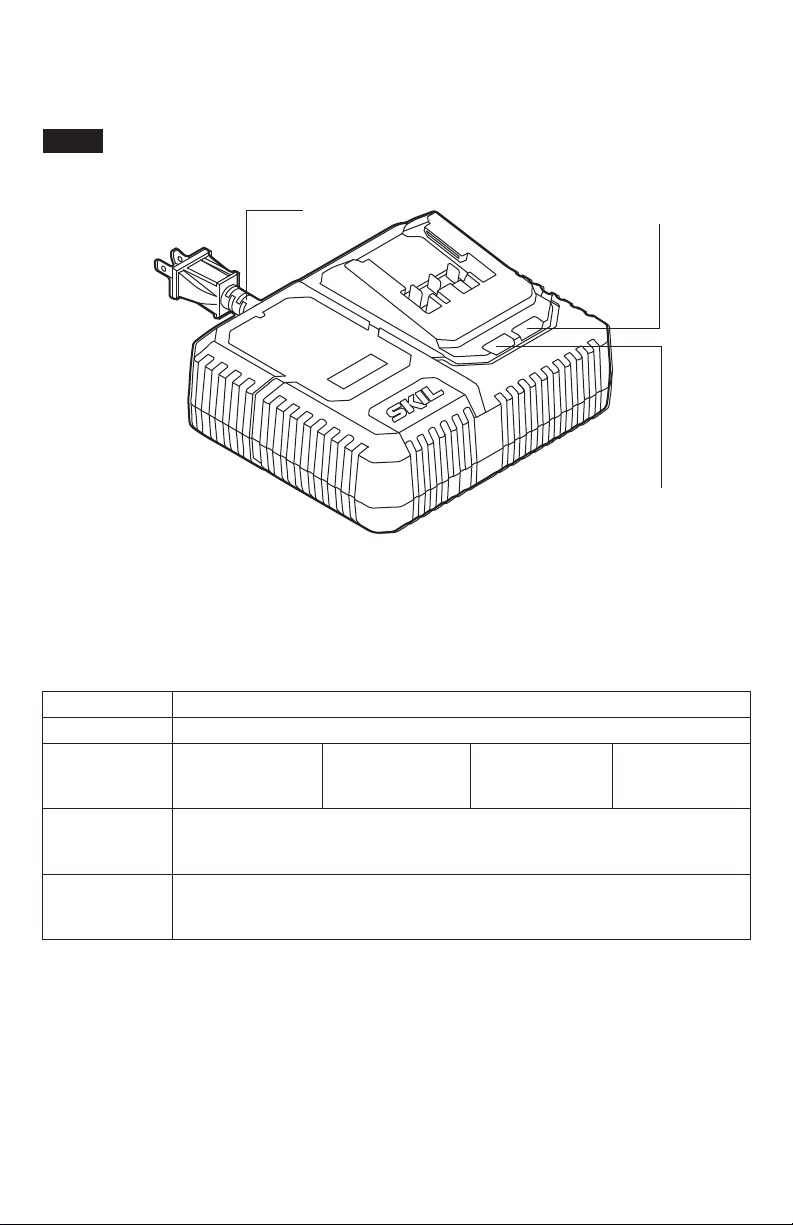
10
GET TO KNOW YOUR CHARGER
PWR
Core
20™ Charger
Charging Indicator
Defect Indicator
Cord
Fig. 1
SPECIFICATIONS
Rated input 120V a.c. 60Hz 150W
Rated output 20V
Battery
Compatibility
2Ah:
SKIL BY519701
SKIL BY519702
2.5Ah:
SKIL BY519703
4Ah:
SKIL BY519601
5Ah:
SKIL BY519603
Recommended
Charging
Temperature
41°F(5°C) ~ 95°F(35°C)
Recommended
Storage
Temperature
32°F (0°C)~104°F (40°C)

11
IMPORTANT CHARGING NOTES
1. The charger was designed to rapidly charge the battery only when the battery temperature
is between 41°F (5°C) and 95°F (35°C). If the battery pack is too hot or too cold, the charger
will not begin charging the battery. (This may happen if the battery pack is hot from heavy
use). Once the battery temperature returns to its safe charging temperature, the charger will
automatically begin charging.
2. A substantial drop in operating time per charge may mean that the battery pack is nearing
the end of its life and should be replaced.
3. Remember to unplug the charger during storage.
4. If battery does not charge properly:
a. Check for power at the outlet by plugging another electrical device into the outlet.
b. Check to see if outlet is connected to a light switch that turns power “off” when the lights
are turned off.
c. Check the battery pack terminals for dirt. Clean with a cotton swab and alcohol, if
necessary.
d. If proper charging still does not occur, take or send the tool, battery pack and charger to
your local SKIL Service Center. Please refer to the Customer Service information on the
cover of this manual.
Note:
Use of chargers or battery packs not sold by SKIL will void the tool warranty.
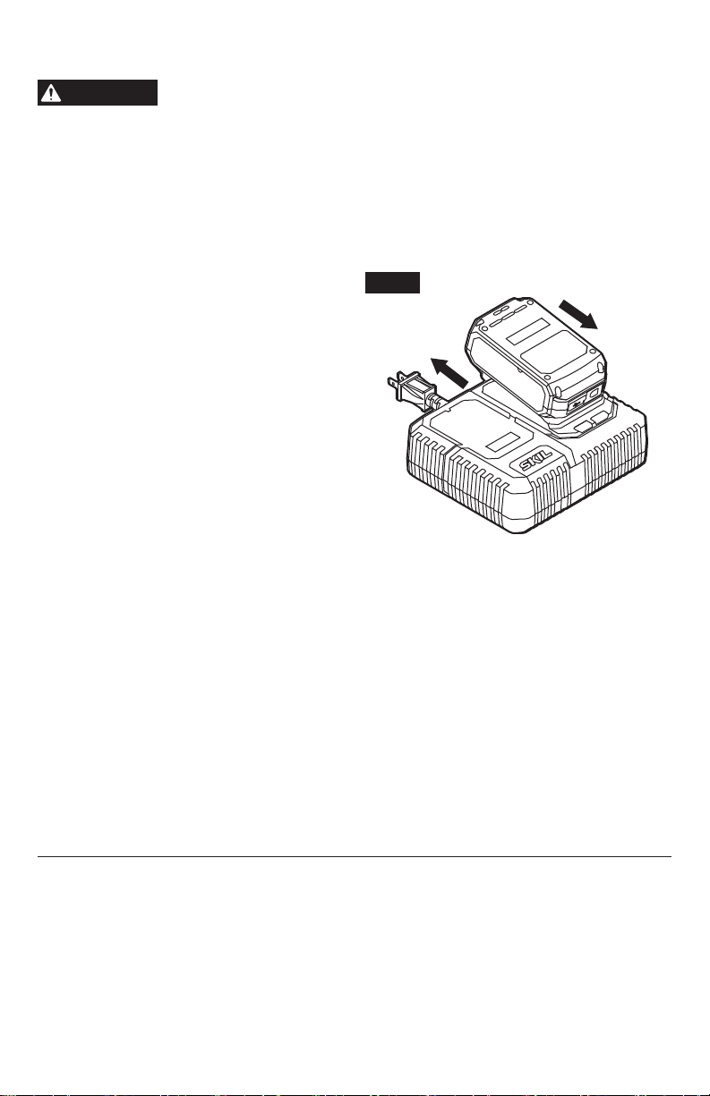
12
OPERATING INSTRUCTIONS
WARNING
To reduce the risk of re, personal injury, and product damage due to
a short circuit, never immerse your charger or battery pack in uid or
allow a uid to ow inside them.
Corrosive or conductive uids, such as seawater, certain
industrial chemicals, and bleach or bleach-containing products, etc, can cause a short circuit.
How to Charge the Battery Pack
NOTICE:
The battery pack is shipped partially charged. Before using it the rst time, fully
charge the battery pack. The charger charges a fully-depleted 2.0Ah battery pack to
approximately 25% capacity in 5 minutes.
a. Charge the battery pack with the correct
charger.
b. Connect the charger to a power supply. The
red Defect Indicator and green Charging
Indicator will shine for one second and then
go out, indicating that the charger self-
inspection is completed.
c. Align the raised ribs of the battery pack with
the slot in the charger.
d. Insert the battery pack into the charger
(Fig. 2).
e. The charger will communicate with the
battery pack to evaluate the condition of the
battery pack.
f. If the battery pack temperature is within the
charging temperature range, the charger will
automatically start charging the battery pack. The green charging indicator will ash during
charging. After the charging is complete, the green charging indicator will remain green,
without ashing.
g. A ashing red defect indicator indicates a defective battery , a defective charger, or a bad
connection between the battery and the charger.
h. A solid red defect indicator indicates that the battery is warmer or colder than the optimal
temperature. Remove the battery pack from the charger. If the battery is too hot, cool
the battery under air ow. If the battery is too cold, place it indoors until it reaches room
temperature.
i. It is not recommended that the battery pack remain on the charger for more than 24 hours.
NOTICE:
If the battery pack cannot accept a charge, the contacts of the charger or battery
pack may be contaminated. Clean the contacts of the charger or battery pack (e. g., by
inserting and removing the battery several times or cleaning with a cotton swab and alcohol) ,
or replace the charger or replace the battery pack, as required.
Fig. 2
Attach
Detach
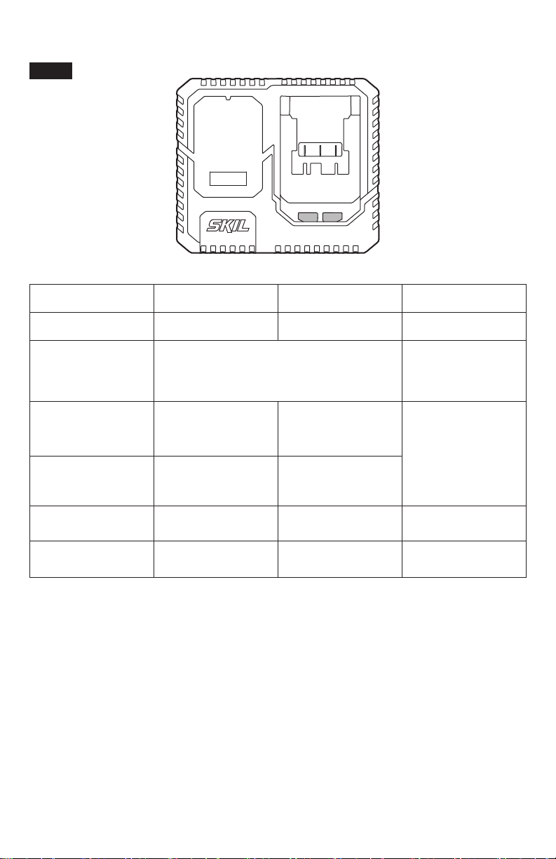
13
Charger Display (Fig. 3)
Fig. 3
Mode
Charging Indicator
(green)
Defect Indicator
(red)
Note
Self-inspection
completed
1 second 1 second Shines for 1 second.
Self-inspection failed Either or both are off
Either or both will
normally have no
reaction when the
charger is plugged in.
Normal charging Flashing Off
The charger will
automatically start
charging the battery
pack, if the battery
pack temperature is
within the charging
temperature range.
Fully Charged Steady green Off
Hot/Cold Battery Off Steady red
Remove the battery
from the charger.
Defective Off Flashing or Off Charging defect.
NOTICE:
Charger may become warm with several continuous charge cycles. This is part of
the normal operation of the charge. Charge in a well ventilated area.

14
Defective Charger
If the charger self-inspection fails to react when the charger is plugged in, the causes include
no power to the charger, bad contacts, or a defective charger. Check to see if the charger self-
inspection can be activated when the charger is plugged in again or plugged into a different
outlet. If it still fails, have the charger serviced by an Authorized SKIL Service Station.
Defective Battery Pack
If the charger detects a problem, the red Defect Indicator will begin ashing. Remove and
re-insert the battery pack in the charger. If the Defect Indicator ashes a second time, try
charging a different battery pack.
a) If a different battery pack charges normally, have the rst defective battery pack serviced by
an Authorized SKIL Service Station.
b) If a different battery pack also indicates “defective,” the charger may be defective. Have the
charger serviced by an Authorized SKIL Service Station.

15
MAINTENANCE
Service
WARNING
Preventive maintenance performed by unauthorized personnel may
result in misplacing of internal wires and components which could
cause serious hazard.
We recommend that all tool service be performed by a SKIL Factory
Service Center or Authorized SKIL Service Station.
General Maintenance
WARNING
When servicing, use only identical replacement parts. Use of any
other parts could create a hazard or cause product damage.
Periodically inspect the entire product for damaged, missing, or loose parts such as screws,
nuts, bolts, caps, etc. Securely tighten all fasteners and caps and do not operate this product
until all missing or damaged parts are replaced. Please contact customer service or an
authorized service center for assistance.
WARNING
To avoid serious personal injury, always remove the battery pack
from the charger/tool when cleaning or performing any maintenance.
Cleaning
WARNING
The tool may be cleaned most effectively with compressed dry air.
Always
wear safety goggles when cleaning tools with compressed air.
Ventilation openings and switch selectors must be kept clean and free of foreign matter. Do
not attempt to clean by inserting pointed objects through openings.
WARNING
Certain cleaning agents and solvents damage plastic parts.
Some of
these are: gasoline, carbon tetrachloride, chlorinated cleaning solvents,
ammonia and household detergents that contain ammonia.
Storage
Store the tool indoors in a place that is inaccessible to children. Keep away from corrosive
agents.
TROUBLESHOOTING
Problem Cause Remedy
Battery pack will not
charge.
1. Charger is not plugged into
a functioning outlet.
2. Battery pack is not properly
inserted into the charger.
3. Bad contacts.
4. Battery is over- or under-
temperature.
5. Battery pack is damaged.
6. Charger is damaged.
1. Conrm that the charger is plugged
into a functioning outlet.
2. Conrm that the battery pack is
inserted into the charger completely.
3. Clean the contacts of the charger or
battery packs.
4. Cool the battery if too hot. Place the
battery indoors if too cold.
5. Have the battery pack serviced by
an Authorized SKIL Service Station.
6. Have the charger serviced by an
Authorized SKIL Service Station.

16
LIMITED WARRANTY OF SKIL CONSUMER TOOLS
2 YEAR LIMITED WARRANTY- LEGAL
Chervon North America, Inc. ("Seller") warrants to the original purchaser only, that all SKIL
consumer BATTERIES AND CHARGERS will be free from defects in material or workmanship for
a period of two years from date of purchase.
Product registration can be completed online at www.Registermyskil.com. Original purchasers
should also retain their receipt as proof of purchase.
Notwithstanding the foregoing, if a SKIL consumer portable power tool is used for industrial,
professional or commercial purposes, the foregoing warranty will apply for a duration of ninety
days, regardless of registration.
SELLER’S SOLE OBLIGATION AND YOUR EXCLUSIVE REMEDY under this Limited Warranty
and, to the extent permitted by law, any warranty or condition implied by law, shall be the repair or
replacement of parts, without charge, which are defective in material or workmanship and which
have not been misused, carelessly handled, or repaired by persons other than Seller or Authorized
Service Station. To make a claim under this Limited Warranty, you must return the complete
product, transportation prepaid, to any SKIL Factory Service Center or Authorized Service Station.
For Authorized SKIL Power Tool Service Stations, please visit www.Registermyskil.com or call
1-877-SKIL-999 (1-877-754-5999).
THIS LIMITED WARRANTY DOES NOT APPLY TO ACCESSORY ITEMS SUCH AS CIRCULAR
SAW BLADES, DRILL BITS.
ANY IMPLIED WARRANTIES APPLICABLE TO A PRODUCT SHALL BE LIMITED IN
DURATION EQUAL TO THE DURATION OF THE EXPRESS WARRANTIES APPLICABLE TO
SUCH PRODUCT, AS SET FORTH IN THE FIRST PARAGRAPH ABOVE. SOME STATES IN
THE U.S., SOME CANADIAN PROVINCES DO NOT ALLOW LIMITATIONS ON HOW LONG AN
IMPLIED WARRANTY LASTS, SO THE ABOVE LIMITATION MAY NOT APPLY TO YOU.
IN NO EVENT SHALL SELLER BE LIABLE FOR ANY INCIDENTAL OR CONSEQUENTIAL
DAMAGES (INCLUDING BUT NOT LIMITED TO LIABILITY FOR LOSS OF PROFITS) ARISING
FROM THE SALE OR USE OF THIS PRODUCT. SOME STATES IN THE U.S. AND SOME
CANADIAN PROVINCES DO NOT ALLOW THE EXCLUSION OR LIMITATION OF INCIDENTAL
OR CONSEQUENTIAL DAMAGES, SO THE ABOVE LIMITATION OR EXCLUSION MAY NOT
APPLY TO YOU.
THIS LIMITED WARRANTY GIVES YOU SPECIFIC LEGAL RIGHTS, AND YOU MAY ALSO
HAVE OTHER RIGHTS WHICH VARY FROM STATE TO STATE IN THE U.S., PROVINCE TO
PROVINCE IN CANADA AND FROM COUNTRY TO COUNTRY.
THIS LIMITED WARRANTY APPLIES ONLY TO PRODUCTS SOLD WITHIN THE UNITED
STATES OF AMERICA, CANADA AND THE COMMONWEALTH OF PUERTO RICO. FOR
WARRANTY COVERAGE WITHIN OTHER COUNTRIES, CONTACT YOUR LOCAL SKIL
DEALER OR IMPORTER.
© Chervon North America, 1203 E. Warrenville Rd, Naperville, IL 60563.
02/19