Loading ...
Loading ...
Loading ...
4. Applyingforceto eitherthetimingbelt idlerpulleyor thetiming
belt idlerbracket,pivotand holdtheidlerbracketagainstthe
springtensionjust farenoughto allowliftingthe timingbeltoff
andabovethe idler pulley.Carefullyreleasethe idler bracket.See
Figure21.
5. Loopthe timingbeltandlift out of the timingpulleyandoverthe
righthandspindleassembly.Maneuverthe belt betweenthe drive
pulleyontop of the spindleassemblyandthe spindlecoverto
remove.
6. Repeattheaboveprocedureto removethe beltfromthe left hand
spindleassemblytimingpulley.Referto Figure21.
7. Loopthe newtimingbeltand maneuverthe belt betweenthe drive
pulleyontop of the righthandspindleassemblyandthe spindle
cover.Lowerthe belt until looselyaroundthe right handtiming
pulley.Referto Figure21.
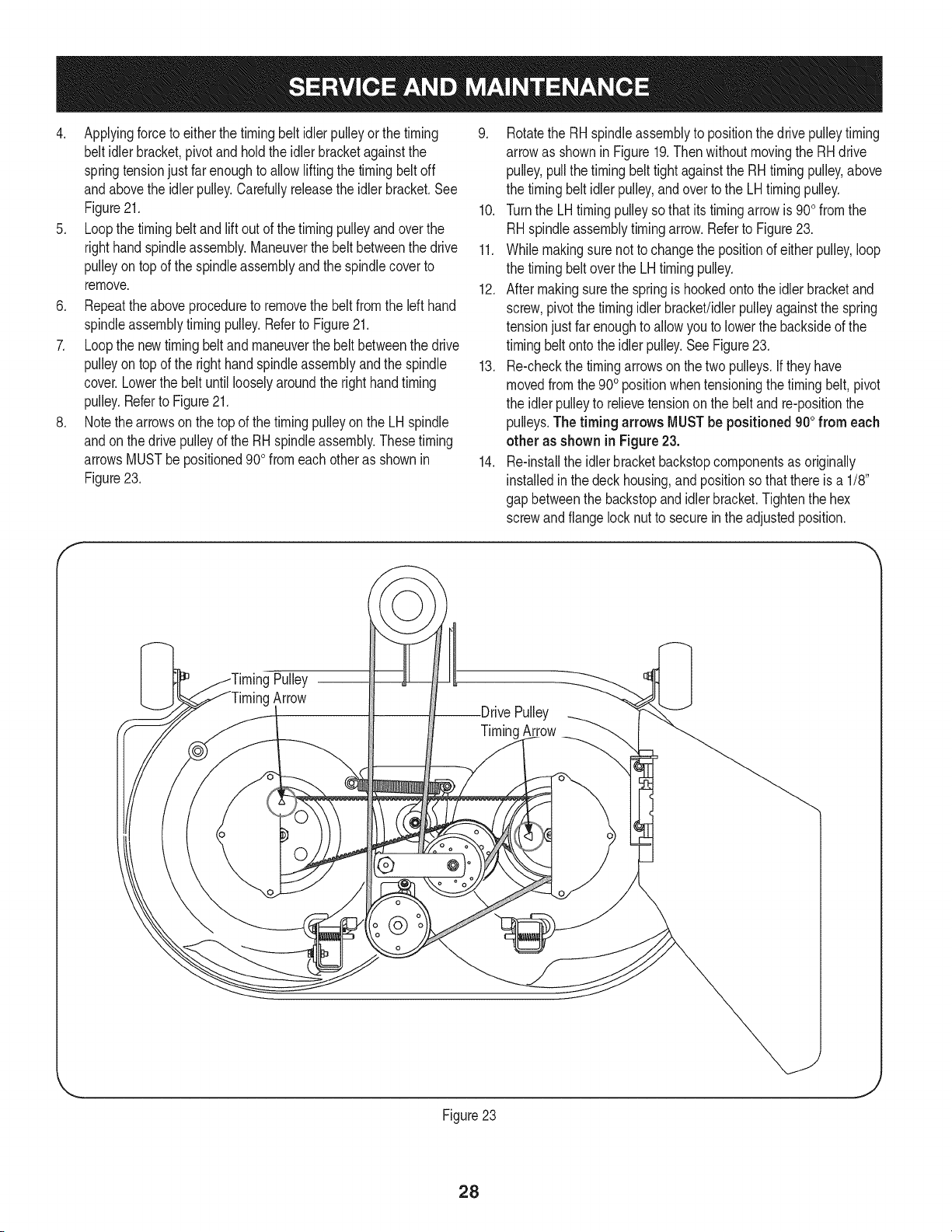
8. Notethe arrowson thetop of the timingpulleyonthe LHspindle
andonthe drivepulleyof the RHspindleassembly.Thesetiming
arrowsMUSTbe positioned90o fromeach otheras shownin
Figure23.
9. Rotatethe RHspindleassemblyto positionthedrive pulleytiming
arrowas shownin Figure19.Then withoutmovingthe RHdrive
pulley,pullthe timingbelt tightagainstthe RHtimingpulley,above
the timingbeltidlerpulley,andover to the LHtimingpulley.
10. Turnthe LHtiming pulleysothat its timingarrowis 900from the
RHspindleassemblytiming arrow.Referto Figure23.
11. Whilemakingsure notto changethe positionof either pulley,loop
the timingbeltoverthe LH timingpulley.
12. After makingsurethe springis hookedonto the idlerbracketand
screw,pivotthetimingidlerbracket!idlerpulleyagainstthe spring
tensionjustfar enoughto allowyouto lowerthe backsideof the
timingbeltonto theidlerpulley.SeeFigure23.
13. Re-checkthe timingarrowson the two pulleys.Iftheyhave
movedfromthe900positionwhentensioningthe timing belt, pivot
the idlerpulleyto relievetensionon the beltand re-positionthe
pulleys.The timing arrows MUSTbe positioned900from each
other as shownin Figure23.
14. Re-installthe idlerbracketbackstopcomponentsas originally
installedin thedeck housing,andpositionso thatthereis a 1/8"
gap betweenthe backstopandidlerbracket.Tightenthe hex
screwandflangelocknut to securein theadjustedposition.
Pulley
Arrow
@
Pulley
TimingArrow
Figure23
28
Loading ...
Loading ...
Loading ...