
Loading ...
Loading ...
Loading ...
BLADES
Besureto shutthe engineoff, removeignitionkey,disconnectthe
sparkplugwire(s)to preventunintendedstartingbeforeremovingthe
cuttingblade(s)for sharpeningor replacement.Protectyourhands
b_ usng heavygovesor a ragto graspthecutt ng bade.
The bladesmay be removedas follows:
1. Removethe deckfrombeneaththe tractor,(referto CuttingDeck
Removal)then gentlyflip the deckoverto exposeits underside.
NOTE:Placea blockof woodbetweenthedeck housingand the
cuttingedgeof the bladeto helpin breakingloosethehex nut securing
the blade.
2. Usea 15/16"wrenchto loosenthehex flangenutsecuringthe
bladeto the bottomof the spindleassembly.Securethe spindle
by eitherholdingthe bladetightly,orby usinga secondwrenchto
holdthe nutat the top of the spindle.
3. Continueholdingthe blade ontothe star hub of the spindle,and
removethe flangenut andcuttingblade.
4. Repeatthepreviousstepsto removethe otherblade.
5. Toproperlysharpenthe cuttingblades,removeequal amounts
of metalfrombothends of the bladesalongthecuttingedges,
parallelto the trailingedge,at a 250to 300angle.
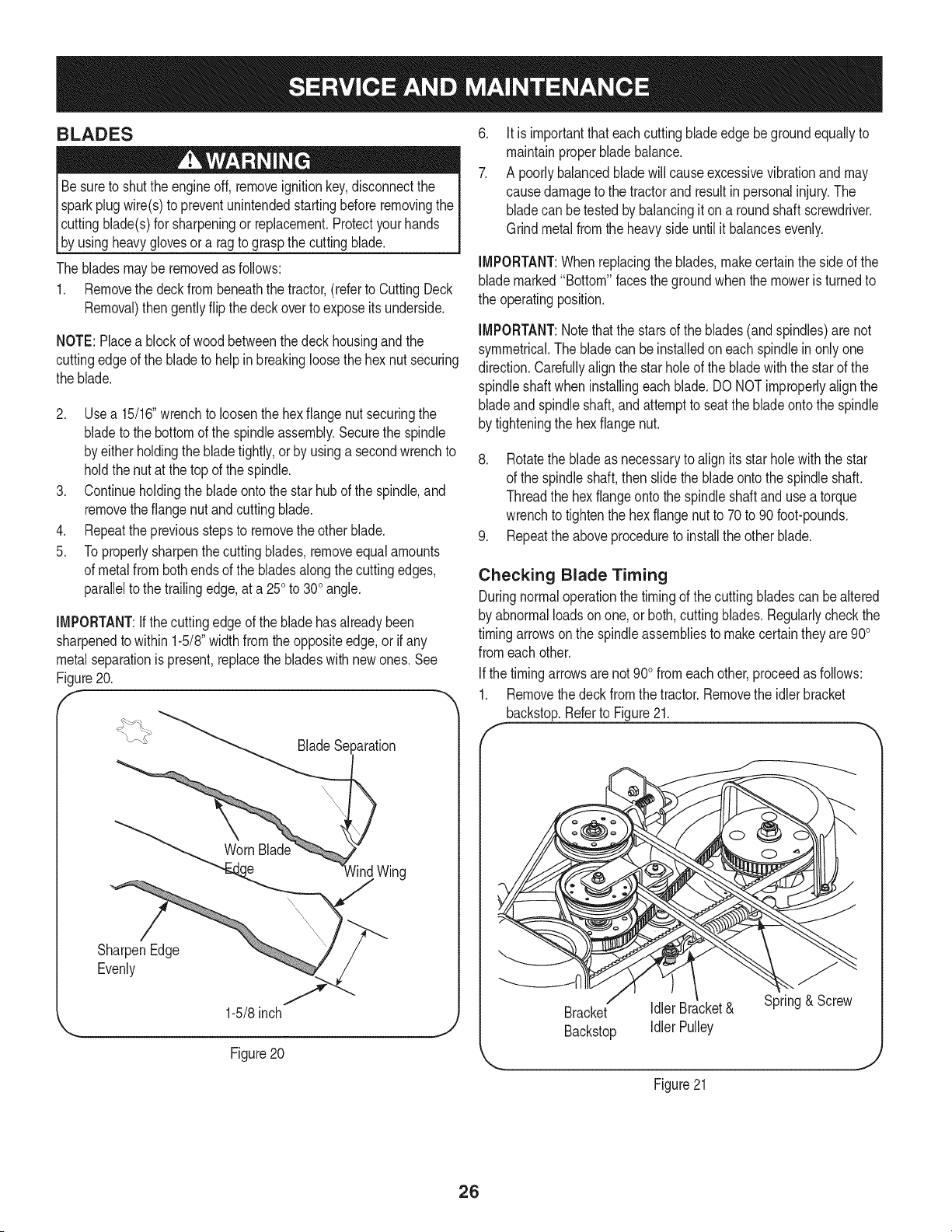
iMPORTANT:ifthecuttingedge of the bladehasalreadybeen
sharpenedto within 1-5/8"widthfromtheoppositeedge,or if any
metalseparationis present,replacethe bladeswith newones.See
Figure20.
f
_aration
)
lind Wing
SharpenEdge
Evenly
1-5/8inch
Figure 20
.
7.
Itis importantthat each cuttingbladeedgebegroundequallyto
maintainproperbladebalance.
A poorlybalancedbladewill causeexcessivevibrationand may
causedamageto the tractorand resultin personalinjury.The
bladecan betestedby balancingit ona round shaftscrewdriver.
Grindmetalfromthe heavyside untilit balancesevenly.
iMPORTANT:When replacingthe blades,makecertainthe sideof the
blademarked"Bottom"facesthegroundwhenthe moweris turnedto
the operatingposition.
iMPORTANT:Notethat the starsof the blades(andspindles)are not
symmetrical.The bladecan be installedon each spindlein onlyone
direction.Carefullyalignthe starholeof thebladewiththe starof the
spindleshaftwheninstallingeachblade.DO NOTimproperlyalignthe
bladeandspindleshaft,andattemptto seatthe bladeontothe spindle
by tighteningthe hexflange nut.
8. Rotatethe bladeas necessaryto alignits star holewiththe star
of the spindleshaft,then slidethe bladeontothe spindleshaft.
Threadthe hexflangeontothe spindleshaft andusea torque
wrenchto tightenthe hex flangenutto 70to 90foot-pounds.
9. Repeatthe aboveprocedureto installthe other blade.
Checking Blade Timing
Duringnormaloperationthe timingof the cuttingbladescan be altered
by abnormalloadson one, or both,cuttingblades.Regularlycheckthe
timingarrowsonthe spindleassembliesto makecertain theyare900
fromeachother.
Ifthe timingarrowsarenot 900fromeachother,proceedas follows:
1. Removethe deckfromthe tractor.Removethe idlerbracket
backstop.Referto Figure21.
f
Bracket Idler Bracket& Spring& Screw
Backstop Idler Pulley
Figure21
26
Loading ...
Loading ...
Loading ...