
Operator's Manual
CRRFr MRN
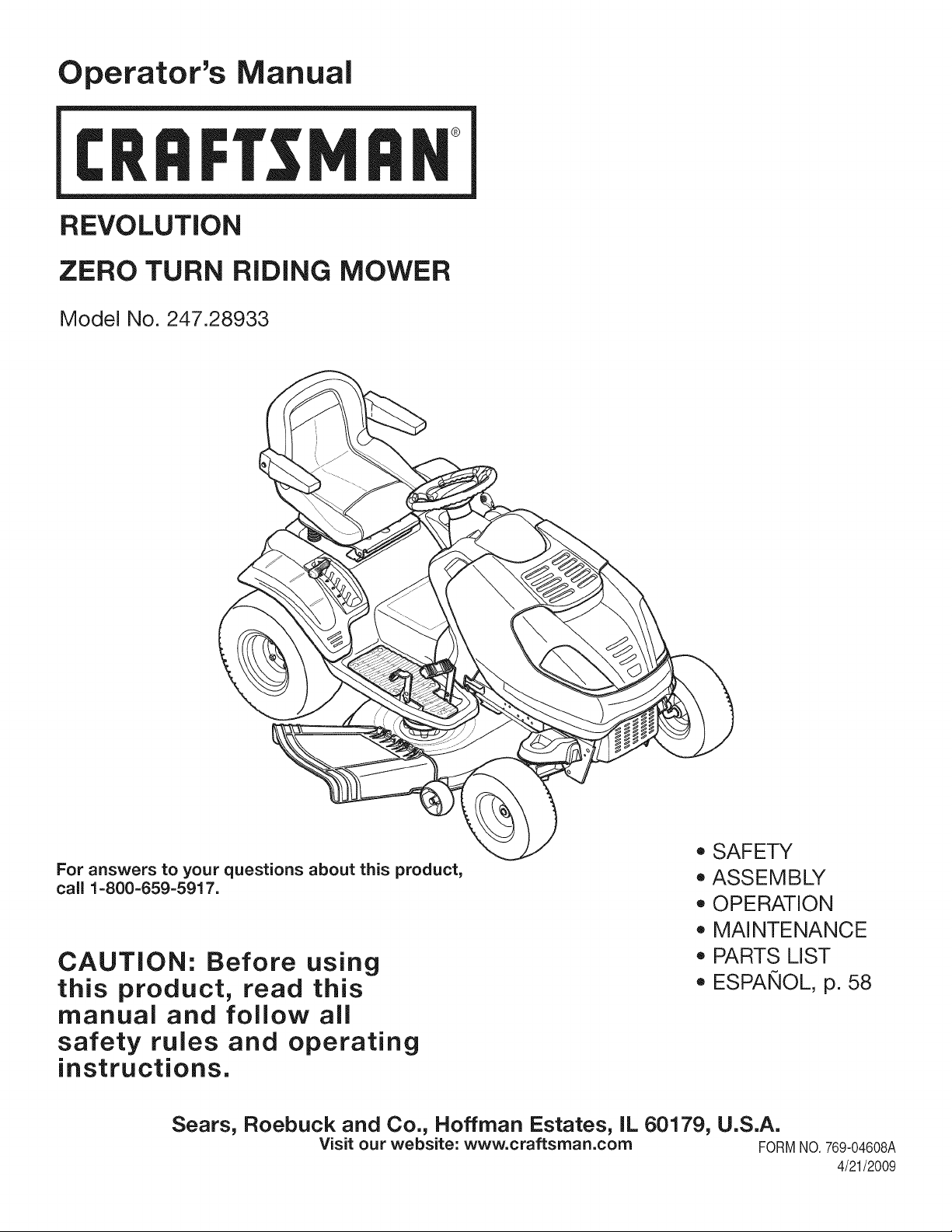
REVOLUTION
ZERO TURN RiDiNG MOWER
Model No. 247.28933
For answers to your questions about this product,
call 1-800-659-5917.
CAUTION: Before using
this product, read this
manual and follow all
safety rules and operating
instructions.
o SAFETY
ASSEMBLY
OPERATION
MAINTENANCE
PARTS LIST
ESPANOL, p. 58
Sears, Roebuck and Co., Hoffman Estates, IL 60179, U.S.A.
Visit our website: www.craftsman.com FORMNO.769-04608A
4/21/2009
WarrantyStatement.................... Page2
SafeOperationPractices.............. Pages3-8
SafetyLabels......................... Page9
Assembly........................... Page10
StandardReplacementParts&AttachmentsPage10
Operation........................ Pages11-17
Service&Maintenance.............. Pages18-29
Off-SeasonStorage................... Page30
Troubleshooting...................... Page31
PartsList......................... Pages32-53
RepairProtectionAgreement............ Page57
Espadol............................. Page58
ServiceNumbers................... BackPage
Craftsman Full Warranty
Whenoperatedandmaintainedaccordingtoallsuppliedinstructions,ifanynon-expendablepartofthisridingequipmentfailsduetoadefectin
materialorworkmanshipwithintwoyearsfromthedateorpurchase,call1-800-659-5917toarrangeforfreein-homerepair.
Theframeandfrontaxlewillberepairedfreeofchargeforfiveyearsfromthedateofpurchaseifdefectiveinmaterialorworkmanship.
Alloftheabovewarrantycoverageappliesforonly90daysfromthedateofpurchaseifthisridingequipmentiseverusedforcommercialor
rentalpurposes.
Inallcases,ifrepairprovesimpossible,theridingequipmentwillbereplacedfreeofchargewiththesameoranequivalentmodel.
Thebatterywillbereplacedfreeofchargefor90daysfromthedateofpurchaseifdefectiveinmaterialorworkmanship(ourtestingprovesthatit
willnotholdacharge).
ThiswarrantycoversONLYdefectsinmaterialandworkmanship.SearswillNOTpayfor:
• Expendableitemsthatbecomewornduringnormaluse,includingbutnotlimitedtoblades,sparkplugs,aircleaners,belts,andoilfilters.
• Standardmaintenanceservicing,oilchanges,ortune-ups.
• Tirereplacementorrepaircausedbypuncturesfromoutsideobjects,suchasnails,thorns,stumps,orglass.
• Tireorwheelreplacementorrepairresultingfromnormalwear,accident,orimproperoperationormaintenance.
• Repairsnecessarybecauseofoperatorabuse,includingbutnotlimitedtodamagecausedbytowingobjectsbeyondthecapabilityofthe
ridingequipment,impactingobjectsthatbendtheframeorcrankshaft,orover-speedingtheengine.
• Repairsnecessarybecauseofoperatornegligence,includingbutnotlimitedto,electricalandmechanicaldamagecausedbyimproper
storage,failuretousethepropergradeandamountofengineoil,failuretokeepthedeckclearofflammabledebris,orfailuretomaintainthe
ridingequipmentaccordingtotheinstructionscontainedintheoperator'smanual.
• Engine(fuelsystem)cleaningorrepairscausedbyfueldeterminedtobecontaminatedoroxidized(stale).Ingeneral,fuelshouldbeused
within30daysofitspurchasedate.
• Normaldeteriorationandwearoftheexteriorfinishes,orproductlabelreplacement.
ThiswarrantyappliesonlywhilethisproductiswithintheUnitedStates.
Thiswarrantygivesyouspecificlegalrights,andyoumayalsohaveotherrightswhichvaryfromstatetostate.
Sears,RoebuckandCo.,HoffmanEstates,IL60179
EngineOil: SAE30
Fuel: UnleadedGasoline
SparkPlug: Champion®RC12YC
Engine: Briggs&StrattonPlatinumV-Twin
ModelNumber.................................................................
SerialNumber.................................................................
Dateof Purchase.............................................................
Recordthe modelnumber,serialnumber
anddateof purchaseabove
© Sears Brands,LLC
2
Thissymbolpointsout importantsafetyinstructionswhich,if not
followed,couldendangerthepersonalsafetyand/orpropertyof
yourselfand others. Readandfollowall instructionsin this manual
beforeattemptingto operatethismachine.Failureto complywith
theseinstructionsmay resultin personalinjury.Whenyou seethis
symbol,HEEDITSWARNING!
CALIFORNIA PROPOSITION 65
EngineExhaust,someof itsconstituents,andcertainvehicle
componentscontainoremitchemicalsknownto Stateof California
to causecancerandbirthdefectsorother reproductiveharm.
Batteryposts,terminals,and relatedaccessoriescontainlead and
leadcompounds,chemicalsknownto the Stateof Californiato
causecancerandreproductiveharm.Washhandsafterhandling.
Thismachinewasbuiltto beoperatedaccordingto the safeopera-
tion practicesinthis manual.As withanytypeof powerequipment,
carelessnessor error on the partof the operatorcan resultin serious
injury.Thismachineis capableof amputatingfingers,hands,toes
andfeetandthrowingdebris.Failureto observethe followingsafety
instructionscouldresultin seriousinjuryor death.
Your Responsibility--Restrict the useof this powermachineto
personswho read,understandandfollowthewarningsand instruc-
tionsin thismanualand on the machine.
SAVE THESE INSTRUCTIONS!
GENERAL OPERATION
• Read,understand,andfollowall instructionson the machineand
in themanual(s)beforeattemptingto assembleandoperate.
Keepthis manualin a safe placefor futureand regularreference
andfor orderingreplacementparts.
• Befamiliarwithall controlsandtheir properoperation.Knowhow
to stopthe machineanddisengagethemquickly.
• Neverallowchildrenunder14yearsoldto operatethis machine.
Children14 yearsold and over shouldreadandunderstandthe
operationinstructionsandsafetyrulesinthismanualandshould
betrainedandsupervisedbya parent.
• Neverallowadultsto operatethis machinewithoutproper
instruction.
• Tohelpavoidbladecontactor a thrownobjectinjury,keep
bystanders,helpers,childrenand pets at least75feetfromthe
machinewhile it is in operation.Stopmachineif anyoneenters
the area.
• Thoroughlyinspectthe areawherethe equipmentis to be used.
Removeall stones,sticks,wire, bones,toys,andotherforeign
objectswhich couldbe pickedup and thrownby the blade(s).
Thrownobjectscan causeseriouspersonalinjury.
• Planyour mowingpatternto avoiddischargeof materialtoward
roads,sidewalks,bystandersand the like.Also, avoiddischarg-
ingmaterialagainstawall orobstructionwhich maycause
dischargedmaterialto ricochetback towardthe operator.
• Alwayswear safetyglassesor safetygogglesduringoperation
andwhile performingan adjustmentor repairto protectyoureyes.
Thrownobjectswhichricochetcancauseseriousinjuryto the
eyes.
• Wearsturdy,rough-soledworkshoesandclose-fittingslacksand
shirts.Loosefittingclothesandjewelrycanbe caughtin movable
parts.Neveroperatethismachineinbarefeetorsandals.
• Beawareof the mowerand attachmentdischargedirectionand
do not pointit at anyone.Donot operatethe mowerwithoutthe
dischargecoverorentiregrasscatcherin its properplace.
Donot put handsor feet near rotatingpartsor underthe cutting
deck. Contactwiththe blade(s)can amputatehandsandfeet.
A missingor damageddischargecovercan causebladecontact
or thrownobjectinjuries.
• Stoptheblade(s)whencrossinggraveldrives,walks,or roads
andwhile notcuttinggrass.
• Watchfor trafficwhenoperatingnearorcrossingroadways.This
machineis not intendedfor useon any public roadway.
• Donot operatethe machinewhile underthe influenceof alcohol
or drugs.
• Mowonly indaylightorgoodartificiallight.
Nevercarrypassengers.
• Disengageblade(s)beforeshiftinginto reverse.Backup slowly.
Alwayslookdownandbehindbeforeandwhile backingto avoida
back-overaccident.
3
• Slowdownbeforeturning.Operatethe machinesmoothly.Avoid
erraticoperationand excessivespeed.
Disengageblade(s),setparkingbrake,stopengineandwaituntil
the blade(s)come to a completestopbeforeremovinggrass
catcher,emptyinggrass,uncloggingchute,removinganygrass or
debris,or makinganyadjustments.
Neverleavea runningmachineunattended.Alwaysturnoff
blade(s),setparkingbrake,stopengineandremovekey before
dismounting.
Useextracare whenloadingorunloadingthe machineintoa
trailerortruck.Thismachineshouldnot bedrivenupor down
ramp(s),becausethe machinecouldtip over,causingserious
personalinjury.The machinemustbe pushedmanuallyon
ramp(s)to loador unloadproperly.
Mufflerand engine becomehotandcan causea burn.Do not
touch.
Checkoverheadclearancescarefullybeforedrivingunderlow
hangingtree branches,wires,dooropeningsetc.,wherethe
operatormay be struckor pulledfrom the machine,whichcould
resultinseriousinjury.
Disengageallattachmentclutchesanddepressthe brakepedal
completelybeforeattemptingto start engine.
Yourmachineisdesignedto cutnormalresidentialgrassof a
heightnomorethan 10".Do not attemptto mowthroughunusually
tall,dry grass(e.g.,pasture)or piles of dry leaves.Drygrassor
leavesmaycontactthe engineexhaustand/or builduponthe
mowerdeckpresentinga potentialfire hazard.
Useonlyaccessoriesand attachmentsapprovedfor this machine
by the machinemanufacturer.Read,understandandfollowall
instructionsprovidedwiththe approvedaccessoryor attachment.
Fora list of approvedaccessoriesandattachments,call 1-800-
659-5917.
Dataindicatesthat operators,age60yearsandabove,are
involvedin a largepercentageof ridingmower-relatedinjuries.
Theseoperatorsshouldevaluatetheirability to operatethe riding
mowersafelyenoughto protectthemselvesand othersfrom
seriousinjury.
If situationsoccurwhicharenot coveredinthismanual,usecare
andgoodjudgment.Contact1-800-659-5917for informationand
assistance.
SLOPE OPERATION
Slopesarea majorfactorrelatedto loss of controland tip-over
accidentswhichcan resultinsevereinjuryor death.Allslopesrequire
extracaution.Ifyoucannotbackupthe slopeor if youfeel uneasyon
it, do not mowit.
Foryoursafety,use the SlopeGuide includedas partof this manual
to measureslopesbeforeoperatingthis machineona slopedor hilly
area. Ifthe slopeis greaterthan15degreesas shownonthe Slope
Guide,do notoperatethis machineon that area or seriousinjurycould
result.
Do:
o
Mowupanddown slopes,not across.Exerciseextremecaution
whenchangingdirectionon slopes.
• Watchfor holes,ruts,bumps,rocks,orother hiddenobjects.
Uneventerraincouldoverturnthe machine.Tallgrass can hide
obstacles.
Useslowspeed.Choosea lowenoughspeedsettingso that
you will nothaveto stopor shiftwhileon the slope.Tiresmay
lose tractionon slopeseventhoughthe brakesarefunctioning
properly.Alwayskeepmachinein gearwhen goingdownslopes
to takeadvantageof enginebrakingaction.
• Followthe manufacturer'srecommendationsfor wheelweights
or counterweightsto improvestability.Forrecommendations,call
1-800-659-5917.
• Useextracarewithgrasscatchersor otherattachments.These
can changethe stabilityof the machine.
Keepallmovementonthe slopesslowandgradual.Do not make
suddenchangesinspeedor direction.Rapidengagementor
brakingcouldcausethe frontof the machineto lift andrapidlyflip
overbackwardswhichcouldcauseseriousinjury.
• Avoidstartingorstoppingona slope.Iftireslosetraction,disen-
gagethe blade(s)andproceedslowlystraightdownthe slope.
DoNot:
• Donot turnon slopesunlessnecessary;then, turnslowlyand
graduallydownhill,if possible.
• Donot mowneardrop-offs,ditchesor embankments.The mower
could suddenlyturnover if a wheelis overthe edgeof a cliff,
ditch,or if an edgecavesin.
• Donot try to stabilizethe machineby puttingyourfoot on the
ground.
• Donot usea grasscatcheron steepslopes.
• Donot mowon wetgrass.Reducedtractioncouldcausesliding.
• Donot attemptto coastdownhill.Over-speedingmaycausethe
operatorto lose controlof the machineresultingin seriousinjury
or death.
• Donot towheavypull behindattachments(e.g.loadeddumpcart,
lawn roller,etc.)on slopesgreaterthan5 degrees.Whengoing
down hill,the extraweighttendsto pushthe tractorandmay
causeyou to loosecontrol.(e.g.tractormayspeedup,braking
and steeringabilityare reduced,attachmentmayjack-knifeand
causetractorto overturn).
4
CHILDREN
Tragicaccidentscanoccurifthe operatoris notalert to the presence
of children.Childrenare often attractedto the machineandthe mowing
activity.Theydo notunderstandthe dangers.Neverassumethat
childrenwill remainwhereyou lastsawthem.
• Keepchildrenout of the mowingareaand inwatchfulcare of a
responsibleadultotherthanthe operator.
• Bealert andturnmachineoff ifa childentersthe area.
• Beforeandwhilebacking,lookbehindanddownfor small
children.
Nevercarrychildren,evenwiththe blade(s)shutoff.Theymay
fall offandbe seriouslyinjuredor interferewith safe machine
operation.
• Useextremecarewhenapproachingblind corners,doorways,
shrubs,trees or otherobjectsthatmayblockyourvisionof a child
whomayrunintothe machine.
Toavoidback-overaccidents,alwaysdisengagethe cutting
blade(s)beforeshiftingintoReverse.Ifequipped,the "Reverse
CautionMode"(bladesoperatewhilemachineridesinreverse)
shouldnotbe usedwhenchildrenor othersare around.
Keepchildrenaway from hotor runningengines.They cansuffer
burnsfroma hotmuffler.
• Removekeywhenmachineisunattendedto preventunauthorized
operation.
Neverallowchildrenunder 14 yearsof ageto operatethis machine.
Children14 and overshouldreadandunderstandthe instructionsand
safeoperationpracticesinthismanualandon the machineandshould
betrainedandsupervisedbyan adult.
TOWING
Towonlywitha machinethathasa hitchdesignedfor towing.Do
not attachtowedequipmentexceptat the hitchpoint.
Followthe manufacturersrecommendationforweight limitsfor
towedequipmentandtowingonslopes.For recommendations,
call 1-800-659-5917.
Neverallowchildrenor othersin or on towedequipment.
Onslopes,theweightof thetowedequipmentmaycause lossof
tractionand loss of control.
Alwaysuseextra cautionwhentowingwitha machinecapableof
makingtightturns(e.g."zero-turn"ride-onmower). Makewide
turnsto avoidjack-knifing.
Travelslowlyandallowextradistanceto stop.
Do notcoastdownhill.
SERVICE
SafeHandlingof Gasoline
Toavoidpersonalinjuryor propertydamageuse extremecarein
handlinggasoline.Gasolineisextremelyflammableandthe vaporsare
explosive.Seriouspersonalinjurycanoccurwhengasolineis spilled
on yourselfor your clotheswhichcan ignite.Washyourskin and
changeclothesimmediately.
• Useonly anapprovedgasolinecontainer.
Neverfill containersinsidea vehicleor on a truckortrailer bed
witha plasticliner.Alwaysplacecontainerson the groundaway
fromyourvehiclebeforefilling.
Whenpractical,removegas-poweredequipmentfromthe truck
or trailerandrefueliton theground.Ifthis isnot possible,then
refuelsuch equipmenton a trailerwith a portablecontainer,rather
than froma gasolinedispensernozzle.
Keepthe nozzleincontactwiththe rim of the fueltankor
containeropeningat all timesuntilfuelingiscomplete.Donot use
a nozzlelock-opendevice.
Extinguishall cigarettes,cigars,pipesandothersourcesof
ignition.
• Neverfuel machineindoors.
Neverremovegascap or addfuelwhilethe engineis hotor run-
ning.Allowengineto coolat leasttwominutesbeforerefueling.
Neveroverfill fuel tank. Filltankto no morethan 1/2inchbelow
bottomof filler neckto allowspace forfuel expansion.
• Replacegasolinecap and tightensecurely.
• Ifgasolineis spilled,wipeitoff the engineand equipment.Move
machineto anotherarea.Wait 5 minutesbeforestartingthe
engine.
• To reducefire hazards,keepmachinefree of grass,leaves,or
otherdebrisbuild-up.Cleanup oil or fuel spillageandremoveany
fuel soakeddebris.
• Neverstorethe machineor fuelcontainerinsidewherethere isan
openflame,sparkor pilotlight as ona waterheater,spaceheater,
furnace,clothesdryeror othergasappliances.
Allowa machineto coolat leastfiveminutesbeforestoring.
GeneralService
• Neverrunanengineindoorsorina poorlyventilatedarea.Engine
exhaustcontainscarbonmonoxide,anodorless,anddeadlygas.
• Beforecleaning,repairing,orinspecting,makecertainthe
blade(s)andallmovingpartshavestopped.Disconnectthespark
plugwireandgroundagainsttheenginetopreventunintended
starting.
• Periodicallychecktomakesurethebladescometocomplete
stopwithinapproximately(5)fivesecondsafteroperatingthe
bladedisengagementcontrol.Ifthebladesdonotstopwithinthe
thistimeframe,yourmachineshouldbeservicedprofessionally
byanauthorizedSearsParts&RepairCenter.
• Checkbrakeoperationfrequentlyasitissubjectedtowearduring
normaloperation.Adjustandserviceasrequired.
• Checktheblade(s)andenginemountingboltsatfrequent
intervalsforpropertightness.Also,visuallyinspectblade(s)
fordamage(e.g.,excessivewear,bent,cracked).Replacethe
blade(s)withtheoriginalequipmentmanufacturer's(O.E.M.)
blade(s)only,listedinthismanual.Useofpartswhichdonot
meettheoriginalequipmentspecificationsmayleadtoimproper
performanceandcompromisesafety!
• Mowerbladesaresharp.Wrapthebladeorweargloves,anduse
extracautionwhenservicingthem.
• Keepallnuts,bolts,andscrewstighttobesuretheequipmentis
insafeworkingcondition.
• Nevertamperwiththe safetyinterlocksystemor othersafety
devices.Checktheir properoperationregularly.
• Afterstrikinga foreignobject,stop the engine,disconnectthe
sparkplugwire(s)andgroundagainstthe engine.Thoroughly
inspectthe machinefor anydamage.Repairthe damagebefore
startingandoperating.
• Neverattemptto makeadjustmentsor repairsto the machine
whilethe engineis running.
• Grasscatchercomponentsand the dischargecoverare subject
to wearanddamagewhich couldexposemovingpartsor allow
objectsto be thrown.Forsafetyprotection,frequentlycheck
componentsand replaceimmediatelywith originalequipment
manufacturer's(O.E.M.)partsonly,listedinthis manual.Useof
partswhichdo not meetthe originalequipmentspecificationsmay
leadto improperperformanceandcompromisesafety!
• Donot changethe enginegovernorsettingsorover-speedthe
engine.The governorcontrolsthe maximumsafe operatingspeed
of the engine.
Maintainor replacesafetyand instructionlabels,as necessary.
• Observeproperdisposallawsandregulationsfor gas, oil, etc.to
protecttheenvironment.
• Accordingto the ConsumerProductsSafetyCommission(CPSC)
andthe U.S.EnvironmentalProtectionAgency(EPA),this product
has anAverageUsefulLifeof seven(7)years,or 270 hours
of operation.At the endof the AverageUsefulLife,buy anew
machineor havethe machineinspectedannuallybya Searsor
otherqualifiedservicedealerto ensurethatall mechanicaland
safetysystemsareworkingproperlyand not wornexcessively.
Failureto do so can resultin accidents,injuriesor death.
DO NOT MODIFY ENGINE
Toavoid seriousinjuryor death,do notmodifyengineinanyway.
Tamperingwiththe governorsettingcanlead to a runawayengineand
causeit to operateat unsafespeeds.Nevertamper with factorysetting
of enginegovernor.
NOTICE REGARDING EMISSIONS
Engineswhich are certifiedto complywith Californiaand federal
EPAemissionregulationsfor SORE(SmallOffRoadEquipment)are
certifiedto operateon regularunleadedgasoline,and may include
the followingemissioncontrol systems:EngineModification(EM)and
ThreeWayCatalyst(TWO)if so equipped.
SPARK ARRESTOR
Thismachineis equippedwithan internalcombustionengineand
shouldnotbe usedonor nearanyunimprovedforest-covered,
brushcoveredor grass-coveredland unlessthe engine'sexhaust
systemisequippedwith a sparkarrestermeetingapplicablelocalor
statelaws(if any).
Ifa sparkarresteris used,it shouldbe maintainedin effectiveworking
orderby the operator.Inthe Stateof Californiatheaboveis required
by law (Section4442of the CaliforniaPublicResourcesCode).Other
statesmayhavesimilarlaws.Federallaws applyonfederallands.
A sparkarresterfor the mufflerisavailablethroughyournearestSears
PartsandRepairServiceCenter.
6
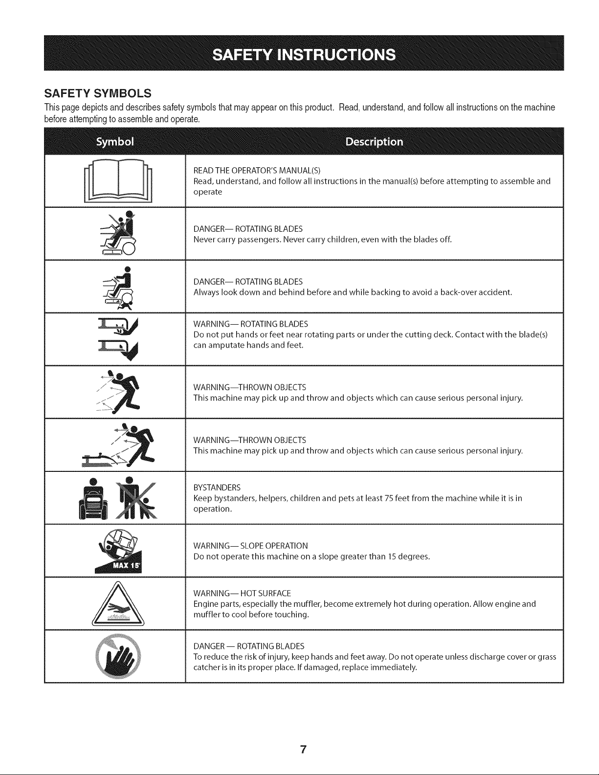
SAFETY SYMBOLS
Thispagedepictsanddescribessafetysymbolsthatmayappearonthis product. Read,understand,and follow all instructionson the machine
beforeattemptingto assembleandoperate.
0
A
READ THE OPERATOR'S MANUAL(S)
Read, understand, and follow all instructions in the manual(s) before attempting to assemble and
operate
DANGER-- ROTATING BLADES
Never carry passengers. Never carry children, even with the blades off.
DANGER-- ROTATING BLADES
Always look down and behind before and while backing to avoid a back-over accident.
WARNING-- ROTATING BLADES
Do not put hands or feet near rotating parts or under the cutting deck. Contact with the blade(s)
can amputate hands and feet.
WARNING--THROWN OBJECTS
This machine may pick up and throw and objects which can cause serious personal injury.
WARNING--THROWN OBJECTS
This machine may pick up and throw and objects which can cause serious personal injury.
BYSTANDERS
Keep bystanders, helpers, children and pets at least 75 feet from the machine while it is in
operation.
WARNING-- SLOPE OPERATION
Do not operate this machine on a slope greater than 15 degrees.
WARNING-- HOT SURFACE
Engine parts, especially the muffler, become extremely hot during operation. Allow engine and
muffler to cool before touching.
DANGER-- ROTATING BLADES
To reduce the risk of injury, keep hands and feet away. Do not operate unless discharge cover or grass
catcher is in its proper place. If damaged, replace immediately.
7
0o
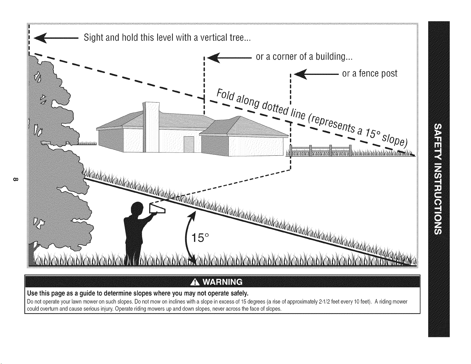
Sight and hold this levelwith a verticaltree...
|
|
|
!
!
|
|
!
|
or a corner of a building...
,_ or afence post
|
|
#Old ',
_. :,uog dotto,_'.
"T,"_ _Presen_ts
alo
, ._ _lOpe_
|
I
15 °
Use this page as a guide to determine slopes where you may not operate safely.
Donot operateyourlawnmoweron such slopes.Do notmowon inclineswitha slope inexcessof 15degrees(a rise of approximately2-1/2feet every 10feet). A ridingmower
couldoverturnandcauseseriousinjury.Operateridingmowersupanddown slopes,neveracrossthe faceof slopes.
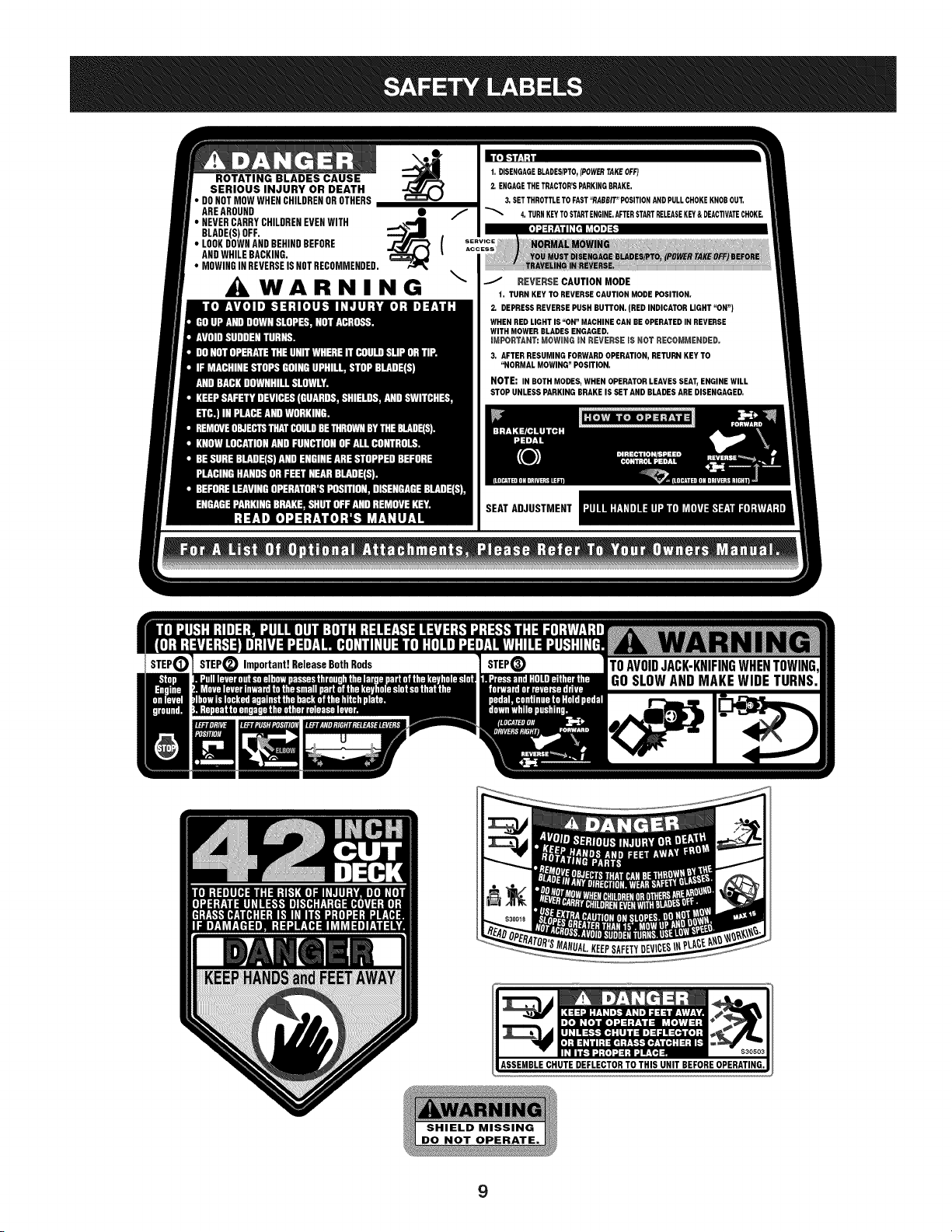
ROTATING BLADES CAUSE
SERIOUS INJURY OR DEATH
• DONOTMOWWHENCHILDRENOROTHERS
AREAROUND •
• BLADE(s)NEVERCARRYoFF.CHILDRENEVENWITH _'_"4m (
• LOOKDOWNANDBEHINDBEFORE
ANDWHILEBACKING.
• MOWINGINREVERSEISNOTRECOMMENDED.
WARNING
\
t. DISENGAGEBLADES/PTO,(POWERTAKEOFF)
2. ENGAGETHETRACTOR'SPARKINGBRAKE.
3. SETTHROTTLETOFAST"RABBIT"POSITIONANDPULLCHOKEKNOBOUT.
4. TURNKEYTOSTARTENGINE.AFTERSTARTRELEASEKEY&DEACTIVATECHOKE.
REVERSE CAUTION MODE
t. TURN KEY TO REVERSE CAUTION MODE POSITION.
2, DEPRESS REVERSE PUSH BUTTON. (BED INDICATOR LIGHT "ON")
WHEN RED LIGHT IS "ON" MACHINE CAN BE OPERATED IN REVERSE
WITH MOWER BLADES ENGAGED.
mMPORTANT: MOWING mN REVERSE iS NGT RECGMMENDED.
3, AFTER RESUMING FORWARD OPERATION, RETURN KEY TO
"NORMAL MOWING" POSITION.
NOTE: IN BOTH MODES, WHEN OPERATOR LEAVES SEAT, ENGINE WILL
STOP UNLESS PARKING BRAKE IS SET AND BLADES ARE DISENGAGED,
SEATADJUSTMENT
9
IMPORTANT:Yourtractoris shippedwithmotoroil in theengine.
However,you MUSTcheckthe oil levelbeforeoperating.Referto the
Service& Maintenancesectionfor instructionson checkingtheoil
level.
NOTE: Ifthe batteryis put intoserviceafterthedate shownontop of
battery,chargethebatteryas instructedinthe Service& Maintenance
sectionof thismanual_the tractor.
OPENING THE TRACTOR HOOD
Toattachthe batterycablesandcheckthe engineoil levelthe hood
mustbeopen. Locatethe hood lift notch(Referto Figure2 on page 11)
at the front/centerof the dash panel.Graspingthe hoodat thenotch,
lift andpivotthe hoodforwardto open.
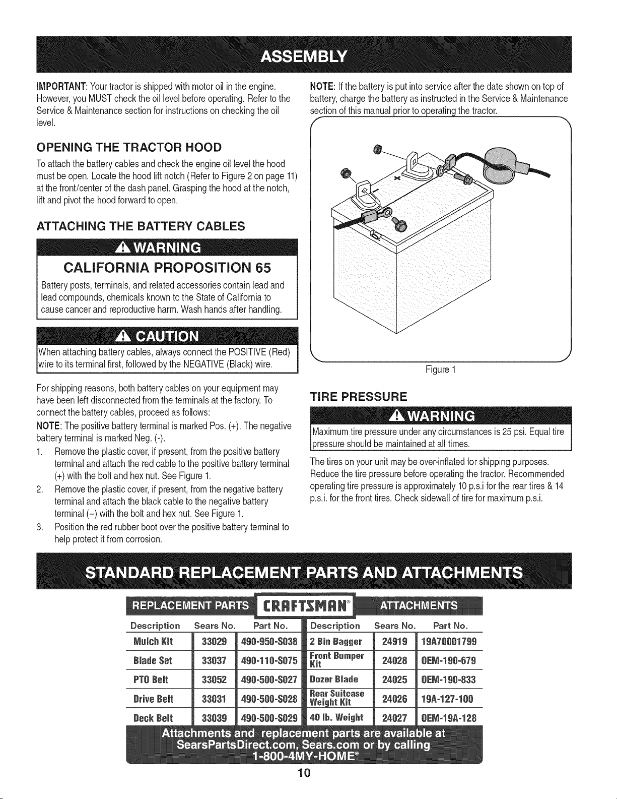
ATTACHING THE BATTERY CABLES
CALIFORNIA PROPOSITION 65
Batteryposts,terminals,and relatedaccessoriescontainleadand
leadcompounds,chemicalsknownto the Stateof Californiato
causecancerandreproductiveharm.Washhandsafterhandling.
Whenattachingbatterycables,alwaysconnectthe POSITIVE(Red)
wireto its terminalfirst,followedby the NEGATIVE(Black)wire.
Figure1
Forshippingreasons,bothbatterycablesonyourequipmentmay
havebeenleftdisconnectedfrom the terminalsat the factory.To
connectthe batterycables,proceedasfollows:
NOTE:Thepositivebatteryterminalis markedPos. (+).The negative
batteryterminalis markedNeg.(-).
1. Removethe plasticcover,if present,fromthe positivebattery
terminaland attachthe redcableto the positivebatteryterminal
(+)with the bolt and hexnut. See Figure1.
2. Removethe plasticcover,if present,fromthe negativebattery
terminaland attachthe black cableto the negativebattery
terminal(-) withthe bolt andhex nut.SeeFigure1.
3. Positionthe red rubberbootoverthe positivebatteryterminalto
helpprotectit fromcorrosion.
TIRE PRESSURE
3ressureshouldbemaintainedatall times.
The tiresonyour unitmaybeover-inflatedfor shippingpurposes.
Reducethe tire pressurebeforeoperatingthe tractor.Recommended
operatingtire pressureis approximately10p.s.ifor the reartires & 14
p.s.i,forthe fronttires.Checksidewallof tire for maximump.s.i.
10
f
K
A
\
P
Q
F
C
E
J
L--
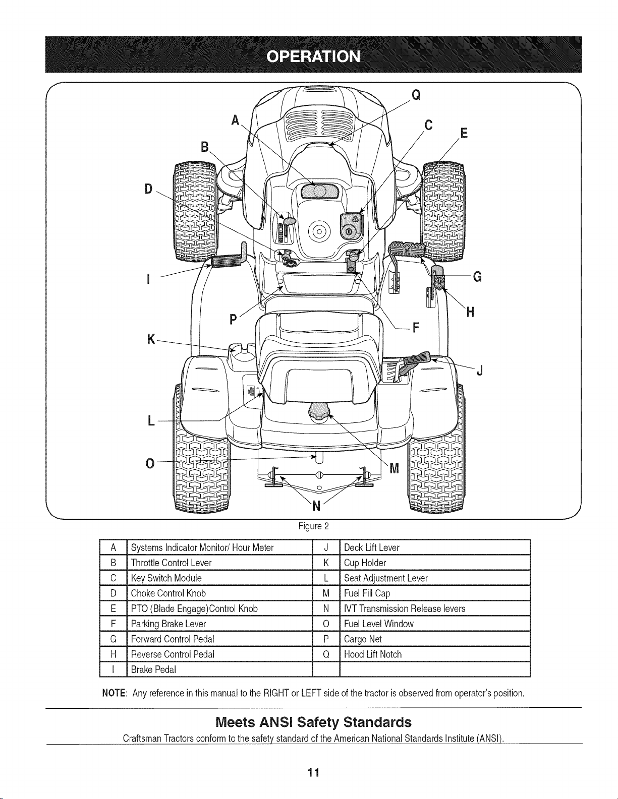
Figure2
A SystemsIndicatorMonitor/HourMeter
B ThrottleControlLever
C KeySwitchModule
D ChokeControlKnob
E PTO(BladeEngage)ControlKnob
F ParkingBrakeLever
G ForwardControlPedal
H ReverseControl Pedal
J DeckLiftLever
K CupHolder
L SeatAdjustmentLever
M FuelFillCap
N IVTTransmissionReleaselevers
0 FuelLevelWindow
P CargoNet
Q HoodLift Notch
I BrakePedal
NOTE: Any referenceinthismanualto the RIGHTor LEFTside of the tractoris observedfromoperator'sposition.
Meets ANSI Safety Standards
CraftsmanTractorsconformto the safetystandardof theAmericanNationalStandardsInstitute(ANSI).
11
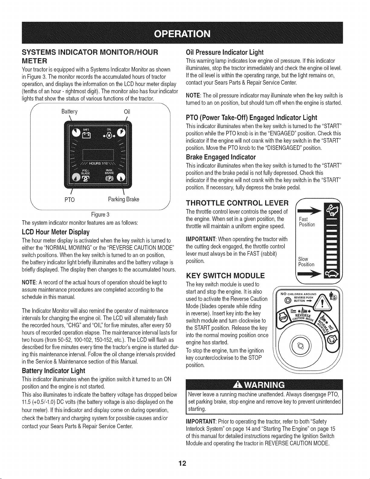
SYSTEMS iNDiCATOR MONITOR/HOUR
METER
Yourtractorisequippedwith a SystemsIndicatorMonitoras shown
in Figure3. The monitorrecordstheaccumulatedhoursof tractor
operation,anddisplaysthe informationonthe LCDhourmeterdisplay
(tenthsof an hour- rightmostdigit).The monitoralso hasfour indicator
lightsthat showthe statusof variousfunctionsof thetractor.
Battery Oil
PTO ParkingBrake
"-.. j
Figure3
The systemindicatormonitorfeaturesareas follows:
LCD Hour Meter Display
The hourmeterdisplayis activatedwhenthe keyswitchis turnedto
eitherthe"NORMALMOWING"or the "REVERSECAUTIONMODE"
switchpositions.Whenthe keyswitchis turnedto anon position,
the batteryindicatorlight brieflyilluminatesand the batteryvoltageis
bridly displayed.The displaythenchangesto the accumulatedhours.
NOTE:A recordof the actual hoursof operationshouldbe keptto
assuremaintenanceproceduresare completedaccordingto the
scheduleinthismanual.
The IndicatorMonitorwill also remindtheoperatorof maintenance
intervalsfor changingtheengineoil. The LCDwill alternatelyflash
the recordedhours,"CHG"and"Oil" for five minutes,after every 50
hoursof recordedoperationelapse.The maintenanceintervallastsfor
twohours(from50-52,100-102,150-152,etc.). The LCDwillflash as
describedfor fiveminuteseverytime the tractor'sengineis starteddur-
ingthis maintenanceinterval.Followthe oilchangeintervalsprovided
inthe Service& Maintenancesectionof thisManual.
Battery indicator Light
Thisindicatorilluminateswhenthe ignitionswitchitturnedto an ON
positionandtheengineis not started.
Thisalsoilluminatesto indicatethe batteryvoltagehasdroppedbelow
11.5(+0.5/-1.0)DCvolts(the batteryvoltageisalso displayedon the
hourmeter).If this indicatorand displaycome on during operation,
checkthe batteryand chargingsystemfor possiblecausesand/or
contactyourSearsParts& RepairServiceCenter.
Oil Pressure indicator Light
Thiswarninglamp indicateslowengineoil pressure.If this indicator
illuminates,stop thetractorimmediatelyand checkthe engineoil level.
Ifthe oil leveliswithinthe operatingrange,butthe light remainson,
contactyour SearsParts& RepairService Center.
NOTE:The oilpressureindicatormayilluminatewhenthe keyswitchis
turnedto an onposition,but shouldturn off whentheengineisstarted.
PTO (Power Take-Off) Engaged indicator Light
Thisindicatorilluminateswhenthe key switchis turnedto the "START"
positionwhilethe PTOknob is in the "ENGAGED"position.Checkthis
indicatorif the enginewill not crankwiththe keyswitchin the"START"
position.Movethe PTOknobto the "DISENGAGED"position.
Brake Engaged indicator
Thisindicatorilluminateswhenthe key switchis turnedto the "START"
positionandthe brakepedalis notfullydepressed.Checkthis
indicatorifthe enginewill not crankwiththe keyswitchinthe"START"
position.If necessary,fullydepressthe brakepedal.
THROTTLE CONTROL LEVER
The throttlecontrollevercontrolsthe speedof
the engine.Whenset in a givenposition,the
throttlewill maintaina uniformenginespeed.
IMPORTANT:Whenoperatingthe tractorwith
the cuttingdeckengaged,thethrottlecontrol
levermustalwaysbein the FAST(rabbit)
position.
KEY SWITCH MODULE
The keyswitchmoduleis usedto
start andstoptheengine.It is also
usedto activatethe ReverseCaution
Mode(bladesoperatewhile riding
in reverse).Insertkey intothe key
switchmoduleand turn clockwiseto
the STARTposition.Releasethe key
intothe normalmowingpositiononce
enginehasstarted.
To stopthe engine,turn the ignition
keycounterclockwiseto the STOP
position.
@
Fast
Position
Slow
Position
Neverleavea runningmachineunattended.AlwaysdisengagePTO,
setparkingbrake,stopengineand removekeyto preventunintended
starting.
IMPORTANT:Priorto operatingthe tractor,referto both"Safety
InterlockSystem"on page 14and"StartingThe Engine"on page15
of this manualfor detailedinstructionsregardingthe IgnitionSwitch
Moduleand operatingthetractorinREVERSECAUTIONMODE.
12
Nevermovethe keyintothe Startpositionwhiletheengineis
running.Doingso maycausedamageto yourengine'sstarter.
CHOKECONTROL
Thechokecontrolknobis locatedonthe lowerIdt sideof the dash
paneland isactivatedby pullingoutward.Activatingthe chokecontrol
closesthechokeplateonthe carburetorand aids in startingthe
engine.
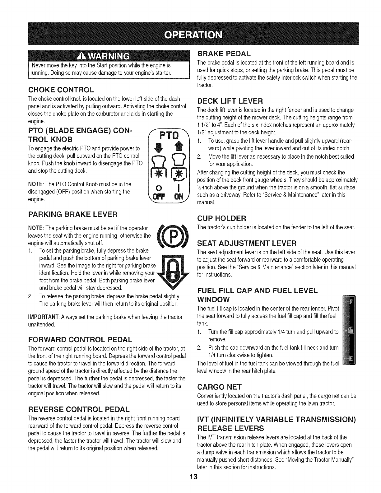
PTO (BLADE ENGAGE) CON-
TROL KNOB
Toengagethe electricPTOand providepowerto
the cuttingdeck, pull outwardon the PTOcontrol
knob.Pushthe knobinwardto disengagethe PTO
andstopthecuttingdeck.
NOTE:The PTOControl Knobmustbe in the
disengaged(OFF) positionwhen startingthe
engine.
F PTO
o I
BRAKE PEDAL
The brakepedalis locatedat the frontof the left runningboardand is
usedfor quick stops,or settingtheparkingbrake.This pedalmustbe
fullydepressedto activatethe safetyinterlockswitchwhen startingthe
tractor.
DECK LIFT LEVER
The decklift leveris locatedinthe rightfenderandis usedto change
the cuttingheightof the mowerdeck.Thecuttingheightsrangefrom
1-1/2"to 4".Eachof the six indexnotchesrepresentanapproximately
1/2"adjustmentto the deckheight.
1. To use,graspthe lift leverhandleandpullslightlyupward(rear-
ward)while pivotingthe leverinwardand out of its indexnotch.
2. Movethe lift leveras necessaryto placein the notchbest suited
for yourapplication.
Afterchangingthe cuttingheightof thedeck, youmustcheckthe
positionof the deckfrontgaugewheels.Theyshouldbeapproximately
lbinch abovethe groundwhenthe tractoris ona smooth,flatsurface
suchas a driveway.Referto "Service& Maintenance"laterin this
manual.
PARKING BRAKE LEVER
NOTE:Theparkingbrakemustbesetif the operator ,_,_%,
leavesthe seatwiththe enginerunning;otherwisethe
tL )
enginewill automaticallyshut off.
1. Tosetthe parkingbrake,fully depressthe brake
pedaland pushthe bottomof parkingbrakelever
inward.Seethe imageto the rightfor parkingbrake
identification.Holdthe leverin while removingyour
footfromthe brakepedal.Bothparkingbrakelever
andbrakepedalwill staydepressed.
2. Toreleasethe parkingbrake,depressthe brakepedalslightly.
Theparkingbrakeleverwill then returnto its originalposition.
IMPORTANT:Alwayssetthe parkingbrakewhen leavingthetractor
unattended.
FORWARD CONTROL PEDAL
Theforwardcontrolpedalis locatedonthe rightsideof the tractor,at
the frontof the rightrunningboard.Depressthe forwardcontrolpedal
to causethe tractorto travelinthe forwarddirection.The forward
groundspeedof thetractorisdirectlyaffectedby the distancethe
pedalisdepressed.Thefurtherthe pedalisdepressed,thefasterthe
tractorwill travel.Thetractorwill slowand the pedal will returnto its
originalpositionwhenreleased.
REVERSE CONTROL PEDAL
The reversecontrolpedalis locatedinthe rightfrontrunningboard
rearwardof theforwardcontrol pedal.Depressthe reversecontrol
pedalto causethetractorto travelin reverse.Thefurther the pedalis
depressed,the fasterthetractorwill travel.The tractorwill slow and
the pedalwill returnto itsoriginal positionwhen released.
CUP HOLDER
The tractor'scup holderis locatedon the fenderto the left of the seat.
SEAT ADJUSTMENT LEVER
The seatadjustmentleveris on the leftside of the seat.Usethis lever
to adjustthe seatforwardor rearwardto a comfortableoperating
position.Seethe "Service&Maintenance"sectionlaterin thismanual
for instructions.
FUEL FILL CAP AND FUEL LEVEL
WINDOW
The fuelfill cap is locatedinthe centerof the rearfender.Pivot
the seatforwardto fullyaccessthe fuelfill cap andfill the fuel
tank.
1. Turnthefill capapproximately1/4 turnandpull upwardto
remove.
2. Pushthe cap downwardon the fueltank fill neck andturn
1/4turn clockwiseto tighten.
The levelof fuel inthe fueltankcan beviewedthroughthefuel
levelwindowin the rear hitchplate.
CARGO NET
Convenientlylocatedon thetractor'sdashpanel,thecargo netcan be
usedto storepersonalitemswhileoperatingthe lawntractor.
IVT (INFINITELY VARIABLE TRANSMISSION)
RELEASE LEVERS
The IVTtransmissionreleaseleversare locatedat the backof the
tractorabovethe rearhitch plate.Whenengaged,theseleversopen
a dumpvalveineachtransmissionwhichallows thetractorto be
manuallypushedshort distances.See"Movingthe TractorManually"
laterinthis sectionfor instructions.
13
Avoid Serious injury or Death
• Goupanddown slopes,not across.
Avoidsuddenturns.
Do notoperatethe unit whereitcouldslip or tip.
If machinestopsgoinguphill,stopbladesand backdownhill
slowly.
• Do notmowwhenchildrenor othersare around.
• Nevercarrychildren,evenwithbladesoff.
• Lookdownandbehindbeforeand whilebacking.
• Keepsafetydevices(guards,shields,andswitches)in place
andworking.
• Removeobjectsthat couldbe thrownbythe blades.
• Knowlocationandfunctionof all controls.
• Besure bladesand engineare stoppedbeforeplacinghandsor
feetnearblades.
• Beforeleavingoperator'sposition,stoptractor,disengage
blades,engageparkingbrake,shutengineoff,and removekey.
Read Operator's Manual
OIL AND GAS FILL-UP
0il
IMPORTANT:Yourtractoris shippedwithmotoroil in theengine.
However,you MUSTcheckthe oil levelbeforeoperating.Seethe
"ServiceandMaintenance"section.
Gasoline
Useextremecarewhenhandlinggasoline.Gasolineis extremely
flammableand the vaporsare explosive.Neverfuel machine
indoorsor whilethe engineis hot or running.Extinguishcigarettes,
cigars,pipes,andothersourcesof ignition.
NOTE: Purchasegasolinein smallquantities.Donot usegasolineleft
overfromthe previousseason,to minimizegumdepositsin the fuel
system.
• Thisengineis certifiedto operateon unleadedgasoline.For best
results,fill the fueltankwithonlyclean,fresh,unleadedgasoline
witha pumpstickeroctaneratingof 87or higher.
• Gasohol(upto 10%ethylalcohol,90%unleadedgasolineby
volume)is anapprovedfuel. Othergasoline/alcoholblends,such
as E85,arenot approved.
• MethylTertiaryButylEther(MTBE)and unleadedgasolineblends
(upto a maximumof 15%MTBEby volume)are approvedfuels.
Othergasoline/etherblendsare notapproved.
• Fillfuel tankoutdoorsorin well-ventilatedarea.
• Donot overfillfuel tank.Filltankto nomorethan 1/2 inchbelow
bottomof filler neckto allow spacefor fuelexpansion.
• Neverremovegascap or addfuelwhilethe engineis hotor run-
ning.Allowengineto coolat leasttwominutesbeforerefueling.
• Ifgasolineis spilled,wipeit off the engineandequipment.Move
machineto anotherarea.Wait 5 minutesbeforestartingthe
engine.
1. Turnthe engineoffand letenginecool at least2 minutesbefore
removingthe fuel cap.The gasolinetank is underthe rear fender,
withthe fuel fill cap locatedin the centerof the rearfender.
The fuelcap is tetheredto the tractorto preventits loss.Do not
attemptto removethe capfromthe tractor.
2. Fillthe fueltankwithgasoline.
3. Reinstallthe fuel cap.
SAFETY INTERLOCK SYSTEM
The safetyinterlocksystemis designedfor safeoperationof the trac-
tor.If thissystemshouldevermalfunction,donot operatethe tractor,
immediatelycontactyourSearsParts& RepairServiceCenter.
• The safetyinterlocksystempreventsthe enginefrom starting
unlessthe parkingbrakeis engagedandthe PTOknob is inthe
disengaged(OFF)position.
• The safetyinterlocksystemwill automaticallyshutoffthe engineif
the operatorleavesthe seat beforeengagingthe parkingbrake.
• The safetyinterlocksystemwill automaticallyshutoffthe engine
if theoperatorleavesthe tractor'sseatwith the PTO(Blade
Engage)knobengaged,regardlessof whetherthe parkingbrake
is engaged.
• Withthe ignitionkeyinthe NORMALMOWINGposition,the
electricPTOclutchwill automaticallyshutoff if the PTOknobis in
the engaged(ON) positionandthe drivepedalis depressedfor
Reversetravel.
Tamperingwithor attemptingto bypassthe SafetyInterlockSwitches
in anywaywill voidyourtractor'swarranty.Donot operatethe tractor
if the interlocksystemis malfunctioning.
REVERSE CAUTION MODE
Useextremecautionwhileoperatingthe tractorinthe REVERSE
CAUTIONMODE.Alwayslookdownandbehindbeforeandwhile
backing.Donot operatethe tractorwhenchildrenorothersare
around.Stopthetractorimmediatelyif someoneentersthe area.
The REVERSECAUTIONMODEpositionof the key switchmodule
allowsthe tractorto beoperatedin reversewiththe blades(PTO)
engaged.
14
IMPORTANT:Mowingin reverseis not recommended.
Touse the REVERSECAUTIONMODE:
IMPORTANT:TheoperatorMUSTbe seatedinthe tractorseat.
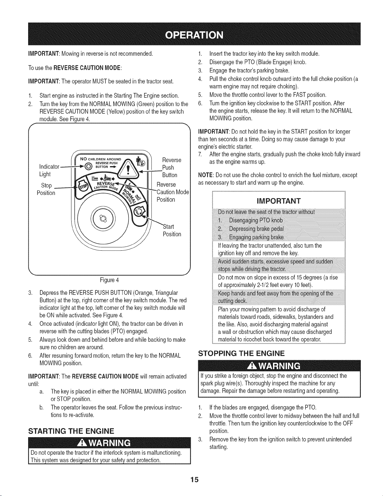
1. Startengineas instructedin the StartingThe Enginesection.
2. Turnthe keyfromthe NORMALMOWING(Green)positionto the
REVERSECAUTIONMODE(Yellow)positionof the keyswitch
module.SeeFigure4.
Light
Stop
Position
N OoHILDREN AROUND
BUTTON
Reverse
Push
Button
Reverse
Mode
Position
Position
J
Figure4
3. Depressthe REVERSEPUSHBUTTON(Orange,Triangular
Button)at the top,rightcornerof the keyswitchmodule.The red
indicatorlight at the top,leftcornerof the keyswitchmodulewill
beON whileactivated.See Figure4.
4. Onceactivated(indicatorlightON), the tractorcan be drivenin
reversewiththe cuttingblades(PTO)engaged.
5. Alwayslookdownand behindbeforeandwhilebackingto make
surenochildrenarearound.
6. Afterresumingforwardmotion,returnthe keyto the NORMAL
MOWINGposition.
IMPORTANT:The REVERSECAUTIONMODEwill remainactivated
until:
a. Thekeyis placedin eitherthe NORMALMOWINGposition
orSTOPposition.
b. Theoperatorleavesthe seat.Followthe previousinstruc-
tionsto re-activate.
STARTING THE ENGINE
wasdesic )rotection.
1. Insertthe tractorkeyintothe keyswitchmodule.
2. Disengagethe PTO(BladeEngage)knob.
3. Engagethe tractor'sparkingbrake.
4. Pullthe chokecontrolknoboutwardintothe fullchokeposition(a
warmenginemaynotrequirechoking).
5. Movethe throttlecontrolleverto the FASTposition.
6. Turnthe ignitionkeyclockwiseto the STARTposition.After
the enginestarts, releasethe key.It will returnto the NORMAL
MOWINGposition.
IMPORTANT:Do nothold the key in the STARTpositionfor longer
than tensecondsata time. Doingso maycausedamageto your
engine'selectricstarter.
7. Afterthe enginestarts,graduallypushthe chokeknobfully inward
as the enginewarmsup.
NOTE:Donot usethe chokecontrolto enrichthe fuel mixture,except
as necessaryto startandwarmupthe engine.
IMPORTANT
If leavingthe tractorunattended,alsoturn the
ignitionkeyoff and removethe key.
Do not mowon slopeinexcessof 15degrees(a rise
of approximately2-1/2feet every 10 feet).
Planyourmowingpatternto avoiddischargeof
materialstowardroads,sidewalks,bystandersand
the like.Also,avoiddischargingmaterialagainst
a wallor obstructionwhichmaycausedischarged
materialto ricochetback towardtheoperator.
STOPPING THE ENGINE
Ifyou strikea foreignobject,stopthe engineand disconnectthe
sparkplugwire(s). Thoroughlyinspectthe machinefor any
damage.Repairthe damagebeforerestartingand operating.
1. Ifthe bladesareengaged,disengagethe PTO.
2. Movethe throttlecontrolleverto midwaybetweenthe halfandfull
throttle.Thenturn the ignitionkey counterclockwiseto the OFF
position.
3. Removethe key fromthe ignitionswitchto preventunintended
starting.
15
DRiViNG THE TRACTOR
iMPORTANT:Avoidsuddenstarts,excessivespeedand sudden
stops.
NOTE:YourRevolutiontractoris equippedwith an innovativedrive
system.Itis normalfor someforwardmovementof thetractorto occur
whenthe brakeis released.
.
2.
Brieflydepressthe brakepedalto releasethe parkingbrake.
Movethe throttleleverintothe FAST(rabbit)position.
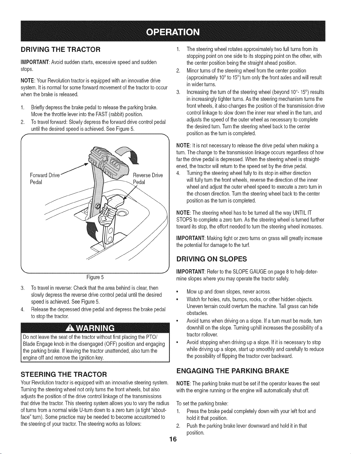
Totravelforward:Slowlydepresstheforwarddrivecontrolpedal
untilthe desiredspeedis achieved.SeeFigure5.
ForwardDrivef
Pedal
Figure5
3. Totravelin reverse:Checkthat theareabehindis clear,then
slowlydepressthe reversedrivecontrolpedal untilthe desired
speedis achieved.See Figure5.
4. Releasethe depresseddrivepedal and depressthe brakepedal
to stopthe tractor.
Do notleavethe seatof thetractorwithoutfirstplacingthe PTO/
BladeEngageknobin the disengaged(OFF)positionand engaging
the parkingbrake.If leavingthe tractorunattended,also turnthe
_engne offand removethe gnton key.
1. The steeringwheel rotatesapproximatelytwo full turns from its
stoppingpointonone sideto its stoppingpointonthe other,with
the centerpositionbeingthe straightaheadposition.
2. Minorturnsof the steeringwheelfromthe centerposition
(approximately100to 150) turnonly the frontaxlesandwill result
in widerturns.
3. Increasingtheturn of the steeringwheel(beyond100.150) results
in increasinglytighterturns.As the steeringmechanismturns the
frontwheels,it alsochangesthe positionof thetransmissiondrive
controllinkageto slow downthe inner rearwheelin theturn, and
adjuststhe speedof theouterwheelas necessaryto complete
the desiredturn. Turnthe steeringwheelbackto the center
positionas the turn is completed.
NOTE: Itis not necessaryto releasethedrive pedalwhenmakinga
turn.Thechangeto the transmissionlinkageoccursregardlessof how
far the drivepedalis depressed.Whenthe steeringwheelis straight-
ened,the tractorwill returnto the speedset by the drivepedal.
4. Turningthe steeringwheelfullyto its stop ineitherdirection
will fullyturnthe frontwheels,reversethe directionof the inner
wheelandadjusttheouterwheelspeedto executea zeroturn in
the chosendirection.Turnthe steeringwheelbackto thecenter
positionas the turn is completed.
NOTE:The steeringwheelhas to beturnedall thewayUNTILIT
STOPSto completea zeroturn.As the steeringwheelis turnedfurther
towardits stop,theeffort neededto turnthe steeringwheelincreases.
IMPORTANT:Makingtightor zeroturns on grass will greatlyincrease
the potentialfor damageto theturf.
DRIVING ON SLOPES
IMPORTANT:Referto the SLOPEGAUGEonpage8 to helpdeter-
mine slopeswhereyou may operatethe tractorsafely.
• Mowupanddown slopes,neveracross.
• Watchfor holes,ruts,bumps,rocks,orother hiddenobjects.
Uneventerraincouldoverturnthe machine.Tallgrass can hide
obstacles.
• Avoidturnswhendrivingon a slope,if a turnmustbe made,turn
downhillon the slope.Turninguphillincreasesthe possibilityof a
tractorrollover.
• Avoidstoppingwhendrivingup a slope,if it is necessaryto stop
whiledrivingupa slope,start upsmoothlyandcarefullyto reduce
the possibilityof flippingthe tractoroverbackward.
STEERING THE TRACTOR
YourRevolutiontractoris equippedwith an innovativesteeringsystem.
Turningthe steeringwheelnotonly turnsthe front wheels,but also
adjuststhe positionof the drivecontrollinkageof thetransmissions
thatdrivethe tractor.Thissteeringsystemallowsyouto varythe radius
of turnsfroma normalwideU-turndownto a zeroturn (a tight"about-
face"turn).Somepracticemaybe neededto becomeaccustomedto
the steeringof yourtractor.The steeringworksas follows:
ENGAGING THE PARKING BRAKE
NOTE:The parkingbrakemustbe set if the operatorleavesthe seat
withthe enginerunningor theenginewill automaticallyshut off.
To setthe parkingbrake:
1. Pressthe brakepedalcompletelydownwith your Idt footand
holdit thatposition.
2. Pushthe parkingbrakeleverdownwardand hold it in that
position.
16
3. Removeyourfootfromthe brakepedal.
4. Releasepressurefromthe parkingbrakelever.
Aftercompletingstep 3, the brakepedalshouldremainin the down
position.If it doesn't,the parkingbrakeis notengaged.Repeatsteps
1-4to engagethe parkingbrake.
Todisengagethe parkingbrake,lightlypressthe brakepedal.
Neverleavea runningmachineunattended.AlwaysdisengagePTO,
setparkingbrake,stop engineand removekey to preventunintended
starting.
ENGAGING THE PTO
Engagingthe PTOtransferspowerto the cuttingdeckor other
(separatelyavailable)attachments.Toengagethe PTO:
1. Movethe throttlecontrol leverto the FAST(rabbit)position.
2. Pullthe PTO/BladeEngageknoboutwardintothe engaged(ON)
position.
NOTE:Alwaysoperatethe tractorwith the throttleleverin the FAST
(rabbit)positionforthe mostefficientuseof the cuttingdeckorother
(separatelyavailable)PTOdrivenattachments.
MOWING
Tohelpavoidbladecontactor a thrownobjectinjury,keepbystand-
ers,helpers,childrenandpetsat least75feetfromthe machine
whileit is inoperation.Stop machineif anyoneentersthearea.
Thistractorisequippedwithoneof Craftsman'shighqualitycutting
decks.The followinginformationwill be helpfulwhenusingthe cutting
deckwithyourtractor.
• Do not mowat highgroundspeed,especiallyif a mulchkitor
grasscollectoris installed.
• For bestresultsit is recommendedthat the firsttwo laps be cut
withthe dischargethrowntowardsthe center.Afterthe first two
laps,reversethe directionto throwthe dischargeto the outside
for the balanceof cutting.This will givea betterappearanceto the
lawn.
• Do notcut thegrasstoo short.Shortgrassinvitesweedgrowth
andyellowsquicklyin dry weather.
• Mowingshouldalwaysbedonewiththe engineat full throttle.
• Underheavierconditionsit may be necessaryto go back overthe
cutareaa secondtimeto geta cleancut.
• Do notattemptto mowheavybrushandweedsandextremelytall
grass.Yourtractoris designedto mowlawns,notclear brush.
• Keepthe bladessharpandreplacethe bladeswhenworn.Refer
to the "Service& Maintenance"sectionof this manualfor proper
bladesharpeninginstructions.
IMPORTANT:Whenstoppingthe tractorfor anyreasonwhileona
grasssurface,always:
1. Engagethe parkingbrake.
2. Shutengineoffand removethe key.
Doingso will minimizethe possibilityof havingyour lawn"browned"by
hotexhaustfrom yourtractor'srunningengine.
MOVING THE TRACTOR MANUALLY
Iffor any reasonthe tractorwill not driveoryou wishto movethe
tractor,engagethetwo transmissionreleaseleversto manuallymove
the tractorshortdistances.
IMPORTANT:Nevertow or drag thetractorwith the rear wheelson the
ground.Evenwith the releaseleversengaged.Doingso will damage
the transmissions.
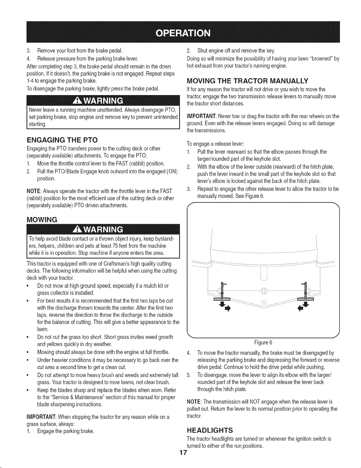
Toengagea releaselever:
1. Pullthe leverrearwardso thatthe elbowpassesthroughthe
larger/roundedpart of the keyholeslot.
2. Withthe elbowof the leveroutside(rearward)of the hitchplate,
pushthe leverinwardin the small partof the keyholeslotso that
lever'selbowis lockedagainstthe backof the hitchplate.
3. Repeatto engagethe otherreleaseleverto allowthe tractorto be
manuallymoved.See Figure6.
f
Figure6
4. To movethetractormanually,the brakemustbedisengagedby
releasingthe parkingbrakeanddepressingthe forwardor reverse
drive pedal.Continueto hold thedrive pedalwhilepushing.
5. Todisengage,movethe leverto align its elbowwith the larger/
roundedpart of the keyholeslotand releasethe leverback
throughthehitchplate.
NOTE:The transmissionwill NOTengagewhenthe releaseleveris
pulledout.Returnthe leverto its normalpositionpriorto operatingthe
tractor.
HEADLIGHTS
The tractorheadlightsare turnedon wheneverthe ignitionswitchis
turnedto eitherof the runpositions.
17
MAINTENANCE SCHEDULE
Beforeperforminganytypeof maintenance/service,disengageall
controlsand stoptheengine.Waituntilallmovingpartshavecometo
acompletestop.Disconnectsparkplugwireandgrounditagainstthe
enginetopreventunintendedstarting.Alwayswearsafetyglassesduring
operationor whileperforminganyadjustmentsor repairs.
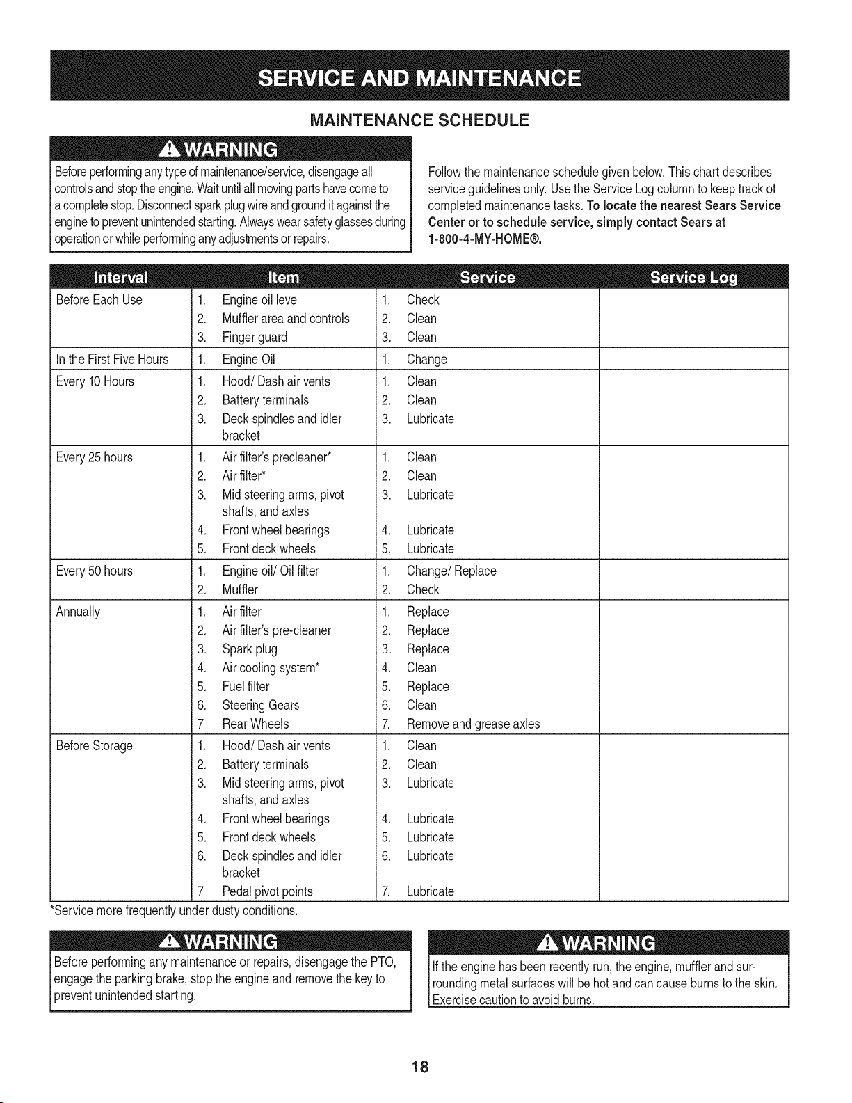
Followthe maintenanceschedulegivenbelow.This chart describes
serviceguidelinesonly. Usethe ServiceLogcolumnto keeptrackof
completedmaintenancetasks.To locate the nearest Sears Service
Centeror to scheduleservice,simplycontactSears at
1-800-4-MY-HOME®.
BeforeEachUse
In the FirstFiveHours
Every10Hours
Every25 hours
Every50 hours
Annually
BeforeStorage
1. Engineoil level
2. Mufflerareaandcontrols
3. Fingerguard
1. EngineOil
1. Hood/Dashairvents
2. Batteryterminals
3. Deckspindlesand idler
bracket
1. Air filter'sprecleaner*
2. Air filter*
3. Midsteeringarms,pivot
shafts,and axles
4. Frontwheelbearings
5. Frontdeckwheels
1. Engineoil/Oil filter
2. Muffler
1. Air filter
2. Air filter'spre-cleaner
3. Sparkplug
4. Air coolingsystem*
5. Fuelfilter
6. SteeringGears
7. RearWheels
1. Hood/Dashairvents
2. Batteryterminals
3. Midsteeringarms,pivot
shafts,and axles
4. Frontwheelbearings
5. Frontdeckwheels
6. Deckspindlesand idler
bracket
7. Pedalpivotpoints
1. Check
2. Clean
3. Clean
1. Change
1. Clean
2. Clean
3. Lubricate
1. Clean
2. Clean
3. Lubricate
4. Lubricate
5. Lubricate
1. Change/Replace
2. Check
1. Replace
2. Replace
3. Replace
4. Clean
5. Replace
6. Clean
7. Removeandgreaseaxles
1. Clean
2. Clean
3. Lubricate
4. Lubricate
5. Lubricate
6. Lubricate
7. Lubricate
*Servicemorefrequentlyunderdustyconditions.
Beforeperformingany maintenanceor repairs,disengagethe PTO,
engagethe parkingbrake,stopthe engineand removethe key to
3reventunintendedstarting.
Ifthe enginehasbeen recentlyrun,the engine,mufflerandsur-
roundingmetalsurfaceswill behotand cancauseburnsto the skin.
Exercisecautionto avoidburns.
18
ENGINE MAINTENANCE
Checking the Engine Oil
Onlyuse highqualitydetergentoil ratedwithAPIserviceclassification
SF,SG,SH,or SJ, Selectthe oil's SAEviscositygradeaccordingto
the expectedoperatingtemperature.Followthe chartbelow.
f_older _ 32°F _Warmer _
Oil Viscosity Chart
Althoughmulti-viscosityoils (5W20,10W30,etc.)improvestarting
in coldweather,they will result in increasedoil consumptionwhen
usedabove32°RCheckyour engineoillevelmorefrequentlyto avoid
possibleenginedamagefrom runninglowonoil.
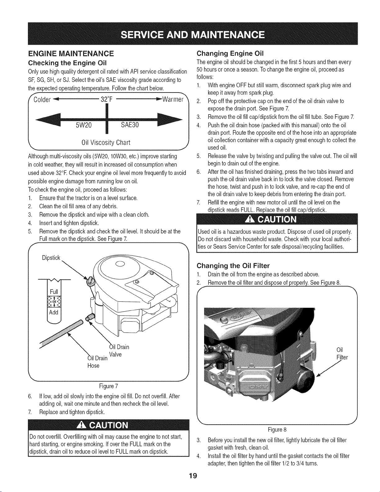
Tocheckthe engineoil, proceedas follows:
1. Ensurethat the tractoris on a levelsurface.
2. Cleantheoil fill areaof anydebris.
3. Removethedipstickandwipe withaclean cloth.
4. Insertandtightendipstick.
5. Removethedipstickandcheckthe oil level.It shouldbeat the
Fullmarkonthe dipstick.SeeFigure7.
F
Dipstick
il Drain
Hose
OilDrain
Valve
Figure7
6. If low,addoil slowlyintothe engineoilfill. Do notoverfill.After
addingoil, waitoneminuteand then recheckthe oil level.
7. Replaceandtightendipstick.
Changing Engine Oil
The engineoil shouldbe changedin the first 5 hoursand thenevery
50 hoursoronce a season.Tochangethe engineoil, proceedas
follows:
1. WithengineOFFbut stillwarm,disconnectsparkplugwireand
keepit awayfrom sparkplug.
2. Popoff the protectivecap on theendof the oil drainvalveto
exposethe drainport.SeeFigure7.
3. Removethe oil fill cap/dipstickfromtheoil fill tube. See Figure7.
4. Pushthe oil drain hose(packedwiththis manual)ontothe oil
drainport. Routethe oppositeendof the hoseintoan appropriate
oil collectioncontainerwith a capacitygreatenoughto collectthe
usedoil.
5. Releasethe valveby twistingand pullingthe valveout. The oil will
beginto drainoutof the engine.
6. Afterthe oil hasfinisheddraining,pressthe twotabsinwardand
pushthe oil drainvalve back in to lock the valveclosed. Remove
the hose,twist andpushinto lockvalve,and re-capthe endof
the oil drainvalveto keepdebrisfromenteringthe drain port.
7. Refillthe enginewithnewmotoroil untilthe oil levelonthe
dipstickreadsFULL.Replacetheoil fill cap/dipstick.
Usedoil is a hazardouswasteproduct.Disposeof usedoil properly.
IDonot discardwithhouseholdwaste.Checkwithyourlocal authori-
[tiesor SearsServiceCenterfor safedisposal/recyclingfacilities.
Changing the Oil Filter
1. Drainthe oil fromthe engineas describedabove.
2. Removetheoilfilteranddis ure8.
Oil
Filter
Donotoverfill.Overfillingwithoil maycausethe engineto not start,
hardstarting,orenginesmoking.If overthe FULLmarkonthe
dipstick,drain oil to reduceoil levelto FULLmarkondipstick.
19
Figure8
3. Beforeyouinstallthe newoilfilter,lightlylubricatethe oilfilter
gasketwithfresh,cleanoil.
4. Installthe oil filter byhand untilthe gasketcontactstheoil filter
adapter,then tightenthe oilfilter 1/2to 3/4 turns.
5. Addoilasdescribedabove.
6. Startandruntheengine.Astheenginewarmsup,checkforoil
leaks.
7. Stoptheengineandchecktheoillevel.ItshouldbeattheFULL
markonthedipstick.
Fuel Filter
3losioncan causesevereburnsor death.
o
1.
.
f
Keepgasolineawayfrom sparks,openflames,pilotlights,heat,
andotherignitionsources.
Checkfuel lines, tank,cap, andfittingsfrequentlyforcracks or
leaks.Replaceif necessary.
Beforereplacingthe fuelfilter,drain the fueltankor closethe fuel
shut-offvalve.
Replacementpartsmustbethe sameand installedin the same
positionas theoriginalparts.
Iffuel spills,waituntil it evaporatesbeforestartingengine.
Beforereplacingthe fuelfilter,drain the fueltankor closethe fuel
shut-offvalve.Otherwise,fuel can leakout andcausea fire or
explosion.
Usepliersto squeezetabsonthe clamps,then slidethe clamps
awayfromthefuel filter.Twistand pullthefuel linesoff of the fuel
filter.SeeFigure9.
Air Cleaner
Iffilters,or coversare notinstalledcorrectlyseriousinjuryor death
could resultfrombackfire.Do notattemptto startthe enginewith
themremoved.
Donot use pressurizedair or solventsto cleanthe air cleaner
cartridge.
.
2.
f
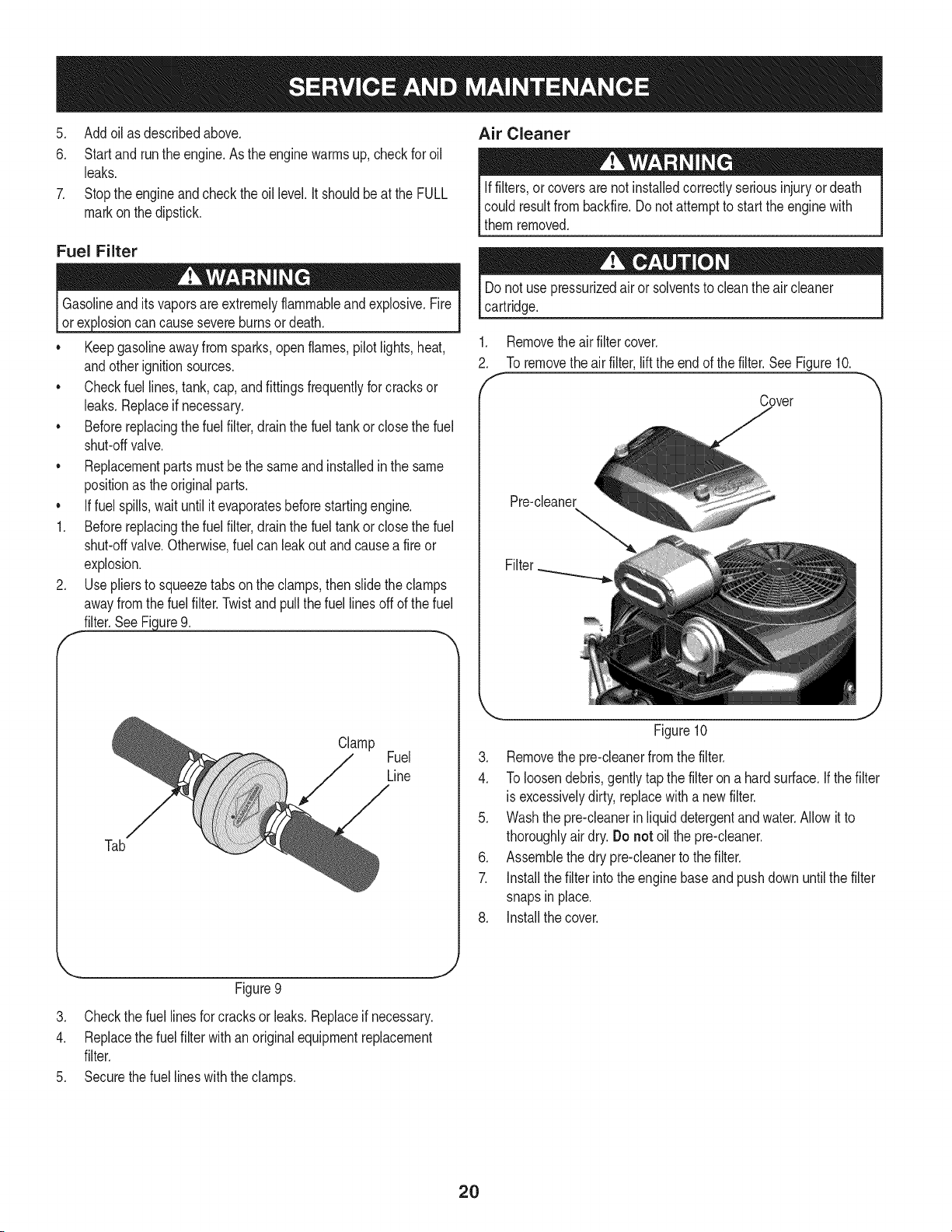
Removethe air filter cover.
To removethe airfilter,liftthe endof thefilter.SeeFigure10.
Cover
Pre-cleaner
Filter
Tab
Clamp
Fuel
Line
Figure10
3. Removethe pre-cleanerfromthe filter.
4. To loosendebris,gentlytapthe filteron a hardsurface.If thefilter
is excessivelydirty,replacewith a newfilter.
5. Washthe pre-cleanerinliquiddetergentandwater.Allowit to
thoroughlyair dry.Do not oilthe pre-cleaner.
6. Assemblethe dry pre-cleanerto the filter.
7. Installthe filterintothe enginebaseand pushdown untilthe filter
snapsin place.
8. Installthe cover.
J
Figure9
3. Checkthe fuel linesfor cracksor leaks.Replaceif necessary.
4. Replacethe fuel filter withan originalequipmentreplacement
filter.
5. Securethe fuel lineswiththe clamps.
2O
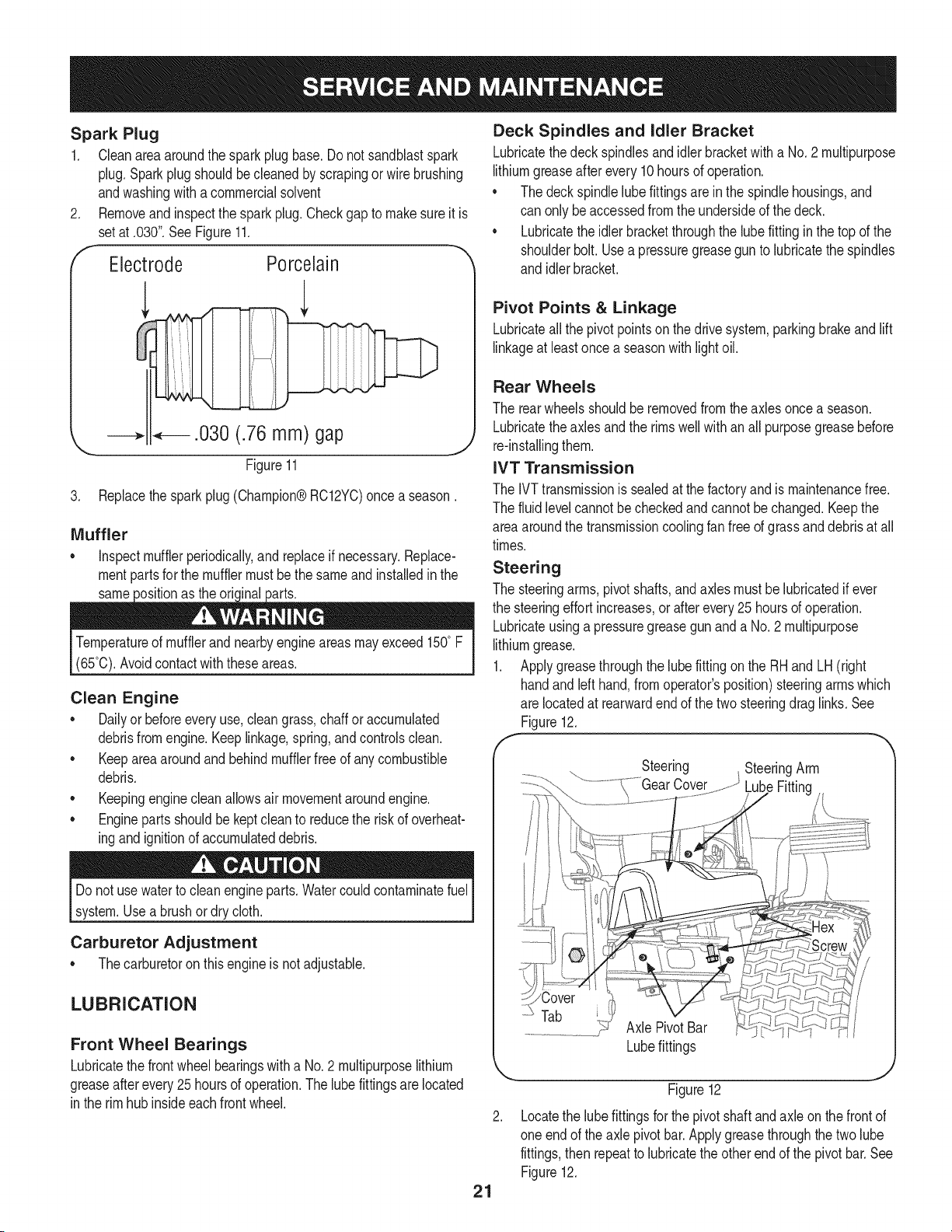
Spark Plug
1. Cleanareaaroundthe sparkplugbase.Do notsandblastspark
plug.Sparkplugshouldbecleanedby scrapingorwire brushing
andwashingwitha commercialsolvent
2. Removeandinspectthe spark plug.Checkgap to makesureit is
setat .030".See Figure11.
f- -._
Electrode Porcelain
3. Replacethesparkplug(Champion®RC12YC)once a season.
Muffler
o inspectmufflerperiodically,and replaceif necessary.Replace-
mentpartsfor the mufflermustbethe sameand installedin the
same the oric
Temperatureof mufflerandnearbyengineareasmayexceed150° F
(65°0).Avoidcontactwiththeseareas.
Clean Engine
o Dailyor beforeeveryuse,cleangrass,chaff or accumulated
debrisfromengine.Keeplinkage,spring,andcontrolsclean.
Keepareaaroundandbehindmufflerfreeof any combustible
debris.
Keepingenginecleanallowsair movementaroundengine.
• Enginepartsshouldbe keptcleanto reducethe risk of overheat-
ingandignitionof accumulateddebris.
Donot usewaterto cleanengineparts.Watercouldcontaminatefuel
system.Usea brushordry cloth.
Carburetor Adjustment
Thecarburetoron thisengineis not adjustable.
LUBRICATION
Front Wheel Bearings
Lubricatethe frontwheelbearingswith a No.2 multipurposelithium
greaseafter every 25 hoursof operation.The lubefittingsarelocated
in the rimhubinsideeachfrontwheel.
Deck Spindles and Idler Bracket
Lubricatethedeckspindlesandidlerbracketwitha No.2 multipurpose
lithiumgreaseafterevery10hoursof operation.
• The deckspindlelubefittingsareinthe spindlehousings,and
can only beaccessedfromthe undersideof thedeck.
• Lubricatetheidlerbracketthroughthe lubefitting inthe top of the
shoulderbolt. Usea pressuregreasegun to lubricatethe spindles
and idlerbracket.
Pivot Points & Linkage
Lubricateallthe pivotpointsonthe drivesystem,parkingbrakeandlift
linkageat leastonce a seasonwith lightoil.
Rear Wheels
The rearwheelsshouldberemovedfrom theaxles oncea season.
Lubricatetheaxlesandthe rimswellwithan all purposegreasebefore
re-installingthem.
IVT Transmission
The IVTtransmissionis sealedat the factoryand is maintenancefree.
The fluidlevelcannotbe checkedand cannotbe changed.Keepthe
areaaroundthe transmissioncoolingfan freeof grassanddebrisat all
times.
Steering
The steeringarms, pivotshafts,andaxlesmustbelubricatedif ever
the steeringeffortincreases,or afterevery25 hoursof operation.
Lubricateusinga pressuregreasegun and a No.2 multipurpose
lithiumgrease.
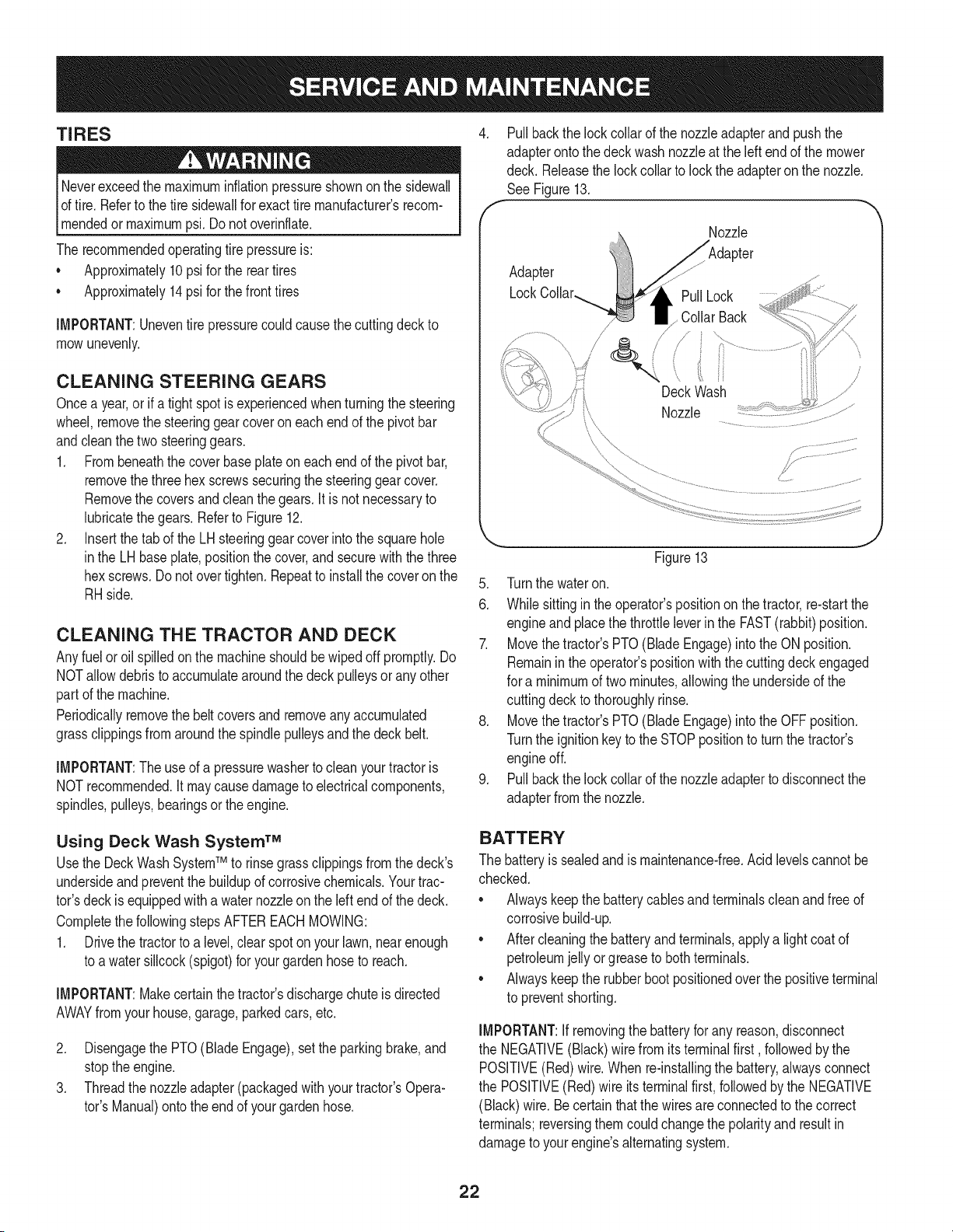
1. Applygreasethroughthe lubefittingonthe RHandLH (right
handandleft hand,from operator'sposition)steeringarmswhich
are locatedat rearwardend of the two steeringdrag links.See
Figure12.
f
Steering SteeringArm
LubeFitting
Tab
Axle PivotBar
21
Lubefittings
Figure12
Locatethe lubefittingsforthe pivotshaftandaxle onthe frontof
oneendof theaxle pivotbar.Applygreasethroughthe two lube
fittings,then repeatto lubricatetheother endof the pivotbar.See
Figure12.
TIRES
Neverexceedthe maximuminflationpressureshownont!e sidewall
of tire.Referto the tire sidewallfor exacttire manufacturers recom-
_mendedor maxmum ps. Do notovernf ate.
The recommendedoperatingtire pressureis:
• Approximately10 psifor the reartires
Approximately14psi for thefronttires
IMPORTANT:Uneventire pressurecouldcausethe cuttingdeckto
mowunevenly.
CLEANING STEERING GEARS
Oncea year,or if a tightspotis experiencedwhenturningthe steering
wheel,removethe steeringgearcoveroneach endof the pivotbar
andcleanthe twosteeringgears.
1. Frombeneaththe coverbaseplateon eachendof the pivotbar,
removethe threehex screwssecuringthe steeringgearcover.
Removethe coversand cleanthe gears.It is not necessaryto
lubricatethe gears.Referto Figure12.
2. Insertthe tabof the LHsteeringgearcoverintothe squarehole
inthe LHbaseplate,positionthe cover,andsecurewiththe three
hexscrews.Donot overtighten.Repeatto installthe coveron the
RHside.
CLEANING THE TRACTOR AND DECK
Anyfuel oroil spilledonthe machineshouldbe wipedoff promptly.Do
NOTallowdebristo accumulatearoundthe deckpulleysor anyother
part of the machine.
Periodicallyremovethe beltcoversandremoveany accumulated
grassclippingsfromaroundthe spindlepulleysandthe deckbelt.
IMPORTANT:The useof a pressurewasherto cleanyourtractoris
NOTrecommended,it maycausedamageto electricalcomponents,
spindles,pulleys,bearingsor the engine.
4. Pullbackthe lockcollarof the nozzleadapterandpushthe
adapteronto thedeck washnozzleat the leftendof the mower
deck. Releasethe lockcollarto lockthe adapteron the nozzle.
See Figure13.
f
Nozzle
Adapter
PullLock
Collar Back
/
/
f,
Deck Wash
Nozzle
Figure13
5. Turnthe wateron.
6. Whilesittingin the operator'spositionon the tractor,re-startthe
engineand placethe throttleleverin the FAST(rabbit)position.
7. Movethetractor'sPTO(Blade Engage)intothe ON position.
Remainintheoperator'spositionwiththe cuttingdeckengaged
for a minimumof two minutes,allowingthe undersideof the
cuttingdeckto thoroughlyrinse.
8. Movethetractor'sPTO(Blade Engage)intothe OFFposition.
Turnthe ignitionkey to the STOPpositionto turn the tractor's
engineoff.
9. Pullbackthe lockcollarof the nozzleadapterto disconnectthe
adapterfrom the nozzle.
Using Deck Wash System TM
Usethe DeckWashSystemTM to rinsegrassclippingsfromthe deck's
undersideand preventthe buildupof corrosivechemicals.Yourtrac-
tor'sdeckis equippedwith a waternozzleonthe leftendof the deck.
Completethe followingstepsAFTEREACHMOWING:
1. Drivethe tractorto a level,clearspotonyour lawn,nearenough
to a watersillcock(spigot)for yourgardenhoseto reach.
IMPORTANT:Makecertain thetractor'sdischargechute is directed
AWAYfrom yourhouse,garage,parkedcars, etc.
2. Disengagethe PTO(Blade Engage),setthe parkingbrake,and
stoptheengine.
3. Threadthe nozzleadapter(packagedwith yourtractor'sOpera-
tot's Manual)ontothe endof yourgardenhose.
BATTERY
The batteryissealedand ismaintenance-free.Acidlevelscannotbe
checked.
Alwayskeepthe batterycablesandterminalscleanandfree of
corrosivebuild-up.
Aftercleaningthe batteryandterminals,applya lightcoatof
petroleumjelly orgreaseto bothterminals.
Alwayskeepthe rubberbootpositionedoverthe positiveterminal
to preventshorting.
IMPORTANT:If removingthe batteryfor any reason,disconnect
the NEGATIVE(Black)wire from its terminalfirst, followedby the
POSITIVE(Red)wire.Whenre-installingthe battery,alwaysconnect
the POSITIVE(Red)wire its terminalfirst, followedby the NEGATIVE
(Black)wire.Becertainthatthe wiresareconnectedto the correct
terminals;reversingthemcouldchangethe polarityandresultin
damageto your engine'salternatingsystem.
22
Charging the Battery
If thetractorhas notbeenput intouse for anextendedperiodof
time,chargethe batterywithanautomotive-type12-voltchargerfor a
minimumof one hourat six amps.
Batteriesgiveoff an explosivegas whilecharging.Chargebatteryin
awell ventilatedarea and keepawayfromanopenflameorpilot light
as ona waterheater,spaceheater,furnace,clothesdryeror other
gasappliances.
Cleaning the Battery
Cleanthe batteryby removingitfrom the tractorand washingwith
a bakingsoda andwater solution.If necessary,scrapethe battery
terminalswith a wire brushto removedeposits.Coatterminalsand
exposedwiringwithgreaseorpetroleumjellyto preventcorrosion.
Battery Failures
Somecommoncausesfor batteryfailureare:
• Incorrectinitialactivation• undercharging
• Overcharging• corrodedconnections
• Freezing
ThesefailuresareNOTcoveredby yourtractor'swarranty.
CHECKING MAIN HARNESS FUSE
• A 20ampfuseis installedin yourtractor'swiringharnessto
protectthe tractor'selectricalsystemfromdamagecausedby
excessiveamperage.
• If theelectricalsystemdoesnot function,or yourtractor'sengine
will notcrank,first checkto becertainthatthefuse hasnot blown.
• Thefusecan befoundinsideof the dashpanelbehindthe battery
tray.You may needto removethe batteryto gainaccessto the
fuse.Alwaysusea fuse with the sameamperagecapacityfor
replacement.
NOTE:A secondfuseholdercanbe foundinsidethedash panel.This
fuseholderisusedfor the optional12voltpoweroutlet.
ADJUSTMENTS
Neverattemptto makeanyadjustmentswhilethe engineis running,
exceptwherespecifiedin theoperator'smanual.Disconnectspark
plugwire(s)beforeperforminganyadjustments,repairsor mainte-
nance.
Steering and Transmission Linkage
Thesteeringtie rodanddraglinksandthe relatedtransmissionlinkage
aresetat the factoryandshouldnot requirefurtheradjustment.
Becauseof the complexadjustmentprocedure,the steeringand
transmissionlinkageshouldonlybe servicedor adjustedby a qualified
mechanic.If youexperienceproblemswith steering,or withthe IVT
transmission,contactyournearestSearsParts& RepairService
Centerto havethetractorinspected.
Seat
Afteradjustingthe seator beforedrivingthetractor,make surethat
the seatadjustmentleveris engagedin the seatindexplateand
thatthe seatwill not move.Do notadjustthe seatwhilethe tractor
is beingdriven.Adjustingthe seatwhilethe tractoris movingcould
causethe operatorto losecontrolof the tractor.
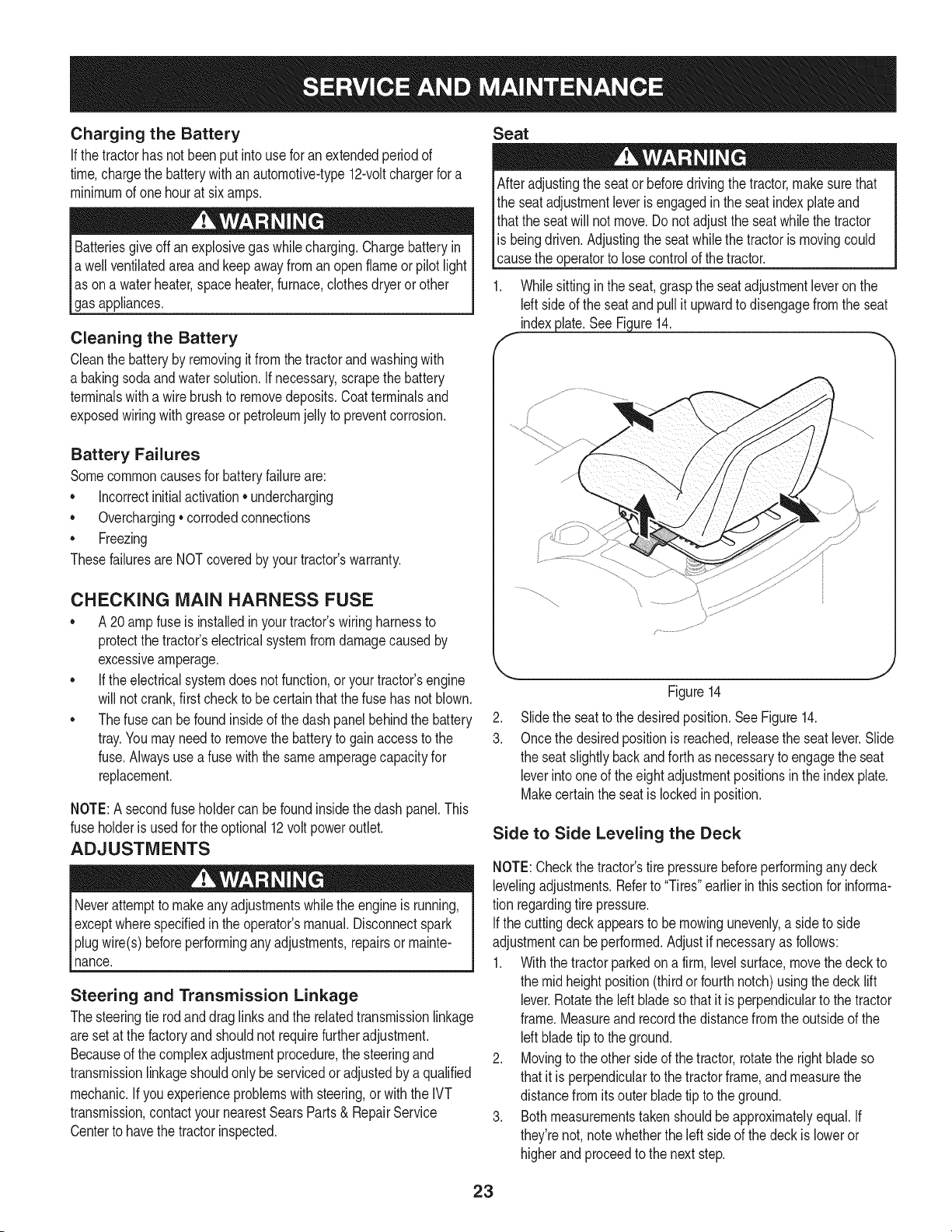
1. Whilesitting inthe seat,graspthe seatadjustmentleveron the
Idt sideof the seatandpullit upwardto disengagefromthe seat
indexplate. See Figure14.
f
Figure14
2. Slidethe seatto thedesiredposition.SeeFigure14.
3. Oncethe desiredpositionis reached,releasetheseat lever.Slide
the seatslightlybackandforthas necessaryto engagetheseat
leverinto one of theeight adjustmentpositionsinthe indexplate.
Makecertainthe seatis lockedin position.
Side to Side Leveling the Deck
NOTE:Checkthe tractor'stire pressurebeforeperforminganydeck
levelingadjustments.Referto "Tires"earlierinthissectionfor informa-
tion regardingtire pressure.
Ifthe cuttingdeckappearsto be mowingunevenly,a sideto side
adjustmentcan beperformed.Adjust if necessaryas follows:
1. Withthe tractorparkedon a firm, levelsurface,movethe deck to
the mid heightposition(thirdorfourthnotch)usingthe decklift
lever.Rotatethe left bladeso that it is perpendicularto the tractor
frame.Measureand recordthe distancefromthe outsideof the
leftbladetip to the ground.
2. Movingto the otherside of thetractor,rotatethe right bladeso
thatit is perpendiculartothe tractorframe,andmeasurethe
distancefrom its outerbladetip to theground.
3. Bothmeasurementstakenshouldbeapproximatelyequal. If
they'renot,notewhetherthe left side of the deck is loweror
higherandproceedto the next step.
23
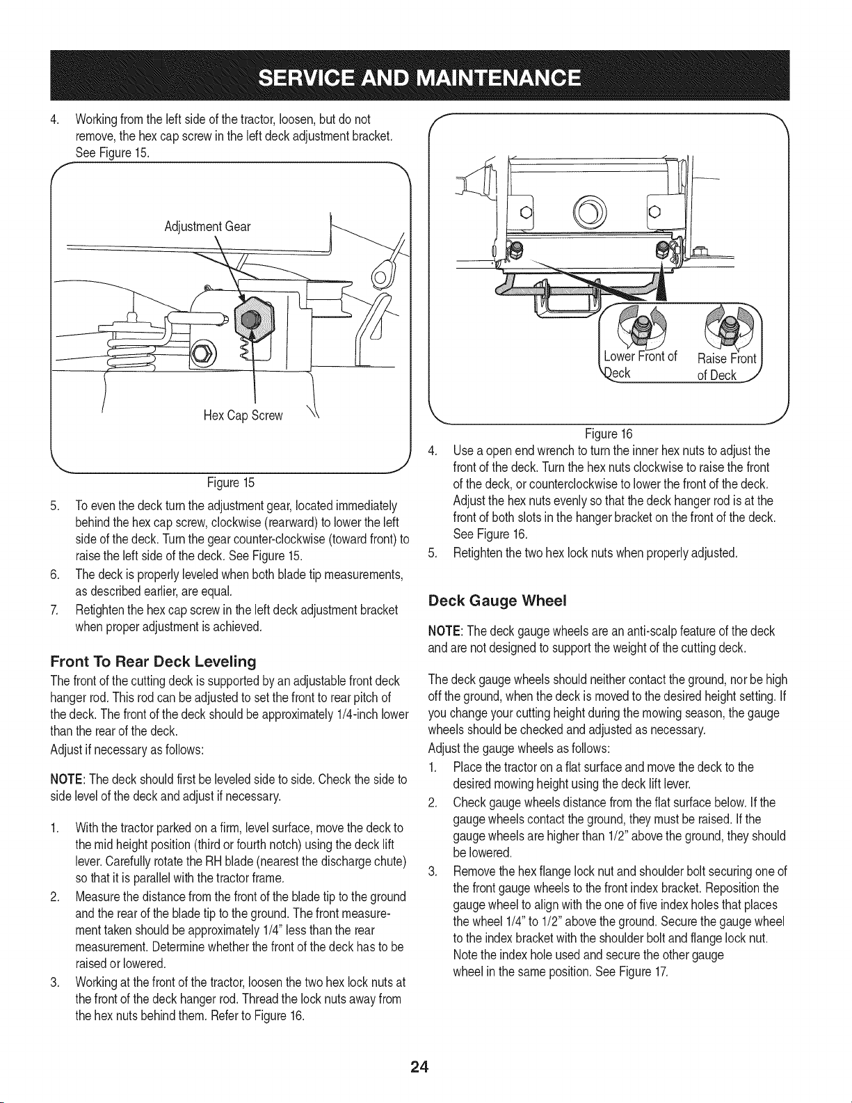
4. Workingfrom the left side of the tractor,loosen,but do not
remove,the hexcap screwin the leftdeckadjustmentbracket.
SeeFigure15.
AdjustmentGear
HexCapScrew
Figure15
5. Toeventhe deckturnthe adjustmentgear,locatedimmediately
behindthe hexcap screw,clockwise(rearward)to lowerthe left
sideof the deck.Turnthe gearcounter-clockwise(towardfront) to
raisethe left sideof the deck.SeeFigure15.
6. Thedeckis properlyleveledwhenbothblade tip measurements,
as describedearlier,are equal.
7. Retightenthe hexcap screwin the left deck adjustmentbracket
whenproperadjustmentis achieved.
Front To Rear Deck Leveling
Thefrontof the cuttingdeckissupportedby an adjustablefrontdeck
hangerrod.This rodcanbeadjustedto setthe frontto rearpitchof
thedeck. Thefrontof the deckshouldbeapproximately1/4-inchlower
thanthe rearof the deck.
Adjustif necessaryas follows:
NOTE:Thedeckshouldfirst beleveledsideto side.Checkthe sideto
side levelof the deck and adjust if necessary.
1. Withthe tractorparkedon a firm,levelsurface,movethe deckto
the midheightposition(thirdor fourthnotch)usingthedeck lift
lever.Carefullyrotatethe RH blade(nearestthe dischargechute)
so thatit is parallelwiththe tractorframe.
2. Measurethe distancefromthe frontof the bladetip to the ground
andthe rearof the bladetip to the ground.The frontmeasure-
menttakenshouldbeapproximately1/4"less thanthe rear
measurement.Determinewhetherthefrontof the deckhasto be
raisedor lowered.
3. Workingat the front of the tractor,loosenthe two hex lock nutsat
thefrontof the deckhangerrod. Threadthe locknutsawayfrom
the hexnutsbehindthem.Referto Figure16.
f
)eck of Deck
Figure16
4. Usea openendwrenchto turnthe innerhexnutsto adjustthe
frontof the deck.Turnthe hexnutsclockwiseto raisethe front
of the deck,or counterclockwiseto lowerthe frontof the deck.
Adjustthe hexnutsevenlysothatthe deckhangerrod isat the
frontof both slotsinthe hangerbracketon the frontof the deck.
See Figure16.
5. Refightenthe twohex locknutswhenproperlyadjusted.
Deck Gauge Wheel
NOTE:The deckgaugewheelsareananti-scalpfeatureof the deck
andare notdesignedto supportthe weightof the cuttingdeck.
The deckgaugewheelsshouldneithercontactthe ground,nor behigh
off the ground,whenthe deck is movedto thedesiredheightsetting.If
you changeyourcuttingheightduringthe mowingseason,the gauge
wheelsshouldbe checkedandadjustedas necessary.
Adjustthe gaugewheelsasfollows:
1. Placethe tractorona fiatsurfaceandmovethe deckto the
desiredmowingheightusingthe decklift lever.
2. Checkgaugewheelsdistancefromthe flat surfacebelow.If the
gaugewheelscontacttheground,theymustbe raised.Ifthe
gaugewheelsare higherthan 1/2"abovethe ground,theyshould
be lowered.
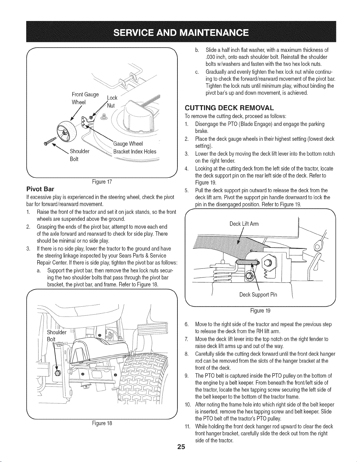
3. Removethe hexflangelocknut andshoulderbolt securingone of
the frontgaugewheelsto the frontindexbracket.Repositionthe
gaugewheelto alignwiththe oneof fiveindexholesthatplaces
the wheel 1/4"to 1/2" abovethe ground.Securethegauge wheel
to the indexbracketwith the shoulderbolt andflangelocknut.
Notethe indexholeusedandsecurethe othergauge
wheelin the sameposition.See Figure17.
24
f
FrontGauge Lock ............
Wheel
Wheel
Shoulder BracketIndexHoles
Bolt
'_. j
Figure17
Pivot Bar
If excessiveplay isexperiencedin the steeringwheel,checkthe pivot
barfor forward/rearwardmovement.
1. Raisethe frontof the tractorand set it on jack stands,sothe front
wheelsaresuspendedabovethe ground.
2. Graspingtheends of the pivotbar,attemptto moveeachend
of the axleforwardand rearwardto checkfor side play.There
shouldbeminimalorno sideplay.
3. If thereis no sideplay,lowerthe tractorto the groundand have
the steeringlinkageinspectedbyyour SearsParts& Service
RepairCenter.If thereis sideplay,tightenthe pivotbaras follows:
a. Supportthe pivotbar,thenremovethe hexlocknutssecur-
ingthe twoshoulderbolts thatpassthroughthe pivot bar
bracket,the pivotbar,andframe.Referto Figure18.
Figure18
b. Slidea half inchflatwasher,with a maximumthicknessof
.030inch,onto eachshoulderbolt.Reinstallthe shoulder
boltsw/washersand fastenwiththe twohexlock nuts.
c. Graduallyandevenlytightenthe hexlocknut whilecontinu-
ingto checktheforward/rearwardmovementof the pivotbar.
Tightenthe locknutsuntil minimumplay,withoutbindingthe
pivotbar'supand down movement,is achieved.
CUTTING DECK REMOVAL
To removethe cuttingdeck,proceedas follows:
1. Disengagethe PTO(BladeEngage)and engagethe parking
brake.
2. Placethe deckgaugewheelsin theirhighestsetting(lowestdeck
setting).
3. Lowerthedeck bymovingthe decklift leverintothe bottomnotch
on the rightfender.
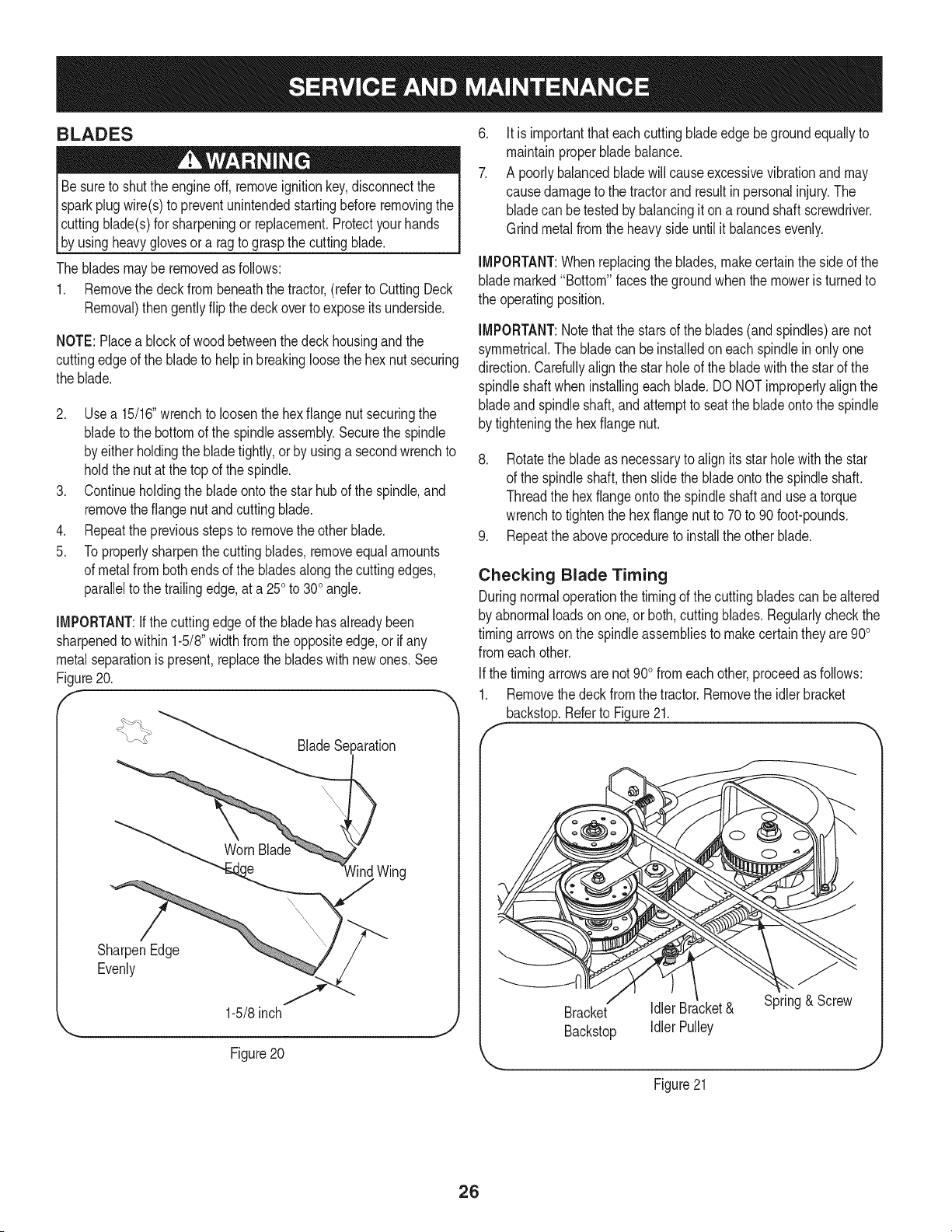
4. Lookingat thecuttingdeckfromthe leftside of the tractor,locate
the decksupportpinon the rearleftside of thedeck. Referto
Figure19.
5. Pullthe decksupportpinoutwardto releasethedeckfromthe
decklift arm.Pivotthe supportpin handledownwardto lockthe
pininthe disengagedposition.Referto Figure19.
DeckLiftArm
DeckSupportPin
25
Figure19
6. Moveto the rightsideof the tractorand repeatthe previousstep
to releasethedeck from the RH lift arm.
7. Movethe deck lift leverintothe top notchon the rightfenderto
raisedeck lift arms up and out of the way.
8. Carefullyslidethe cuttingdeckforwarduntilthe frontdeckhanger
rodcan be removedfromthe slotsof the hangerbracketat the
frontof the deck.
9. The PTObelt is capturedinsidethe PTOpulleyon the bottomof
the engineby a belt keeper.Frombeneaththe front/leftsideof
the tractor,locatethe hextappingscrewsecuringthe left side of
the belt keeperto the bottomof thetractorframe.
10. After notingthe frameholeintowhichright sideof the belt keeper
is inserted,removethe hextappingscrewand belt keeper.Slide
the PTObelt offthe tractor'sPTOpulley.
11. Whileholdingthe front deck hangerrodupwardto clearthe deck
fronthangerbracket,carefullyslidethe deckout fromthe right
sideof the tractor.
BLADES
Besureto shutthe engineoff, removeignitionkey,disconnectthe
sparkplugwire(s)to preventunintendedstartingbeforeremovingthe
cuttingblade(s)for sharpeningor replacement.Protectyourhands
b_ usng heavygovesor a ragto graspthecutt ng bade.
The bladesmay be removedas follows:
1. Removethe deckfrombeneaththe tractor,(referto CuttingDeck
Removal)then gentlyflip the deckoverto exposeits underside.
NOTE:Placea blockof woodbetweenthedeck housingand the
cuttingedgeof the bladeto helpin breakingloosethehex nut securing
the blade.
2. Usea 15/16"wrenchto loosenthehex flangenutsecuringthe
bladeto the bottomof the spindleassembly.Securethe spindle
by eitherholdingthe bladetightly,orby usinga secondwrenchto
holdthe nutat the top of the spindle.
3. Continueholdingthe blade ontothe star hub of the spindle,and
removethe flangenut andcuttingblade.
4. Repeatthepreviousstepsto removethe otherblade.
5. Toproperlysharpenthe cuttingblades,removeequal amounts
of metalfrombothends of the bladesalongthecuttingedges,
parallelto the trailingedge,at a 250to 300angle.
iMPORTANT:ifthecuttingedge of the bladehasalreadybeen
sharpenedto within 1-5/8"widthfromtheoppositeedge,or if any
metalseparationis present,replacethe bladeswith newones.See
Figure20.
f
_aration
)
lind Wing
SharpenEdge
Evenly
1-5/8inch
Figure 20
.
7.
Itis importantthat each cuttingbladeedgebegroundequallyto
maintainproperbladebalance.
A poorlybalancedbladewill causeexcessivevibrationand may
causedamageto the tractorand resultin personalinjury.The
bladecan betestedby balancingit ona round shaftscrewdriver.
Grindmetalfromthe heavyside untilit balancesevenly.
iMPORTANT:When replacingthe blades,makecertainthe sideof the
blademarked"Bottom"facesthegroundwhenthe moweris turnedto
the operatingposition.
iMPORTANT:Notethat the starsof the blades(andspindles)are not
symmetrical.The bladecan be installedon each spindlein onlyone
direction.Carefullyalignthe starholeof thebladewiththe starof the
spindleshaftwheninstallingeachblade.DO NOTimproperlyalignthe
bladeandspindleshaft,andattemptto seatthe bladeontothe spindle
by tighteningthe hexflange nut.
8. Rotatethe bladeas necessaryto alignits star holewiththe star
of the spindleshaft,then slidethe bladeontothe spindleshaft.
Threadthe hexflangeontothe spindleshaft andusea torque
wrenchto tightenthe hex flangenutto 70to 90foot-pounds.
9. Repeatthe aboveprocedureto installthe other blade.
Checking Blade Timing
Duringnormaloperationthe timingof the cuttingbladescan be altered
by abnormalloadson one, or both,cuttingblades.Regularlycheckthe
timingarrowsonthe spindleassembliesto makecertain theyare900
fromeachother.
Ifthe timingarrowsarenot 900fromeachother,proceedas follows:
1. Removethe deckfromthe tractor.Removethe idlerbracket
backstop.Referto Figure21.
f
Bracket Idler Bracket& Spring& Screw
Backstop Idler Pulley
Figure21
26
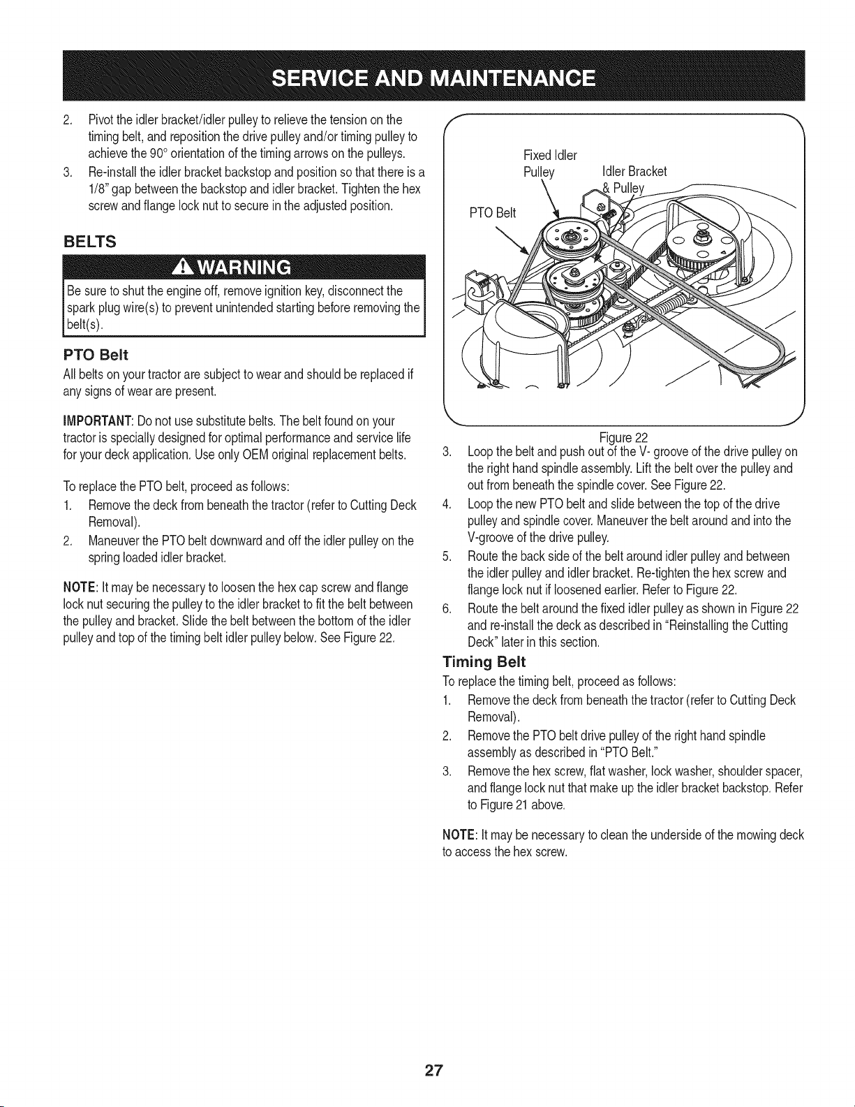
2. Pivotthe idlerbracket/idlerpulleyto relievethe tensionon the
timingbelt,and repositionthe drivepulleyand/or timingpulleyto
achievethe 900orientationof the timingarrowsonthe pulleys.
3. Re-installthe idlerbracketbackstopand positionso that thereis a
1/8"gapbetweenthe backstopandidlerbracket.Tightenthe hex
screwandflange locknutto secureinthe adjustedposition.
BELTS
Besureto shutthe engineoff, removeignitionkey,disconnectthe
sparkplugwire(s)to preventunintendedstartingbeforeremovingthe
belt(s).
PTO Belt
Allbeltsonyour tractorare subjectto wearandshouldbe replacedif
anysignsof weararepresent.
f
PTOBelt
FixedIdler
Pulley Idler Bracket
IMPORTANT:Do not usesubstitutebelts.Thebelt foundonyour
tractoris speciallydesignedfor optimalperformanceand servicelife
for yourdeckapplication.Use only OEMoriginalreplacementbelts.
Toreplacethe PTObelt,proceedas follows:
1. Removethedeck from beneaththe tractor(referto CuttingDeck
Removal).
2. Maneuverthe PTObeltdownwardand off the idler pulleyon the
springloadedidlerbracket.
NOTE:It maybe necessaryto loosenthe hexcap screwand flange
locknut securingthe pulleyto the idlerbracketto fit the beltbetween
the pulleyand bracket.Slide the beltbetweenthe bottomof the idler
pulleyand top of the timing beltidler pulleybelow.SeeFigure22.
,,, j
Figure22
3. Loopthe beltand pushout of theV- grooveof the drivepulleyon
the right handspindleassembly.Lift the belt overthe pulleyand
out frombeneaththe spindlecover.SeeFigure22.
4. Loopthe newPTObelt andslidebetweenthe topof the drive
pulleyand spindlecover.Maneuverthe beltaroundandintothe
V-grooveof the drivepulley.
5. Routethebacksideof the beltaroundidlerpulleyandbetween
the idlerpulleyandidlerbracket.Re-tightenthe hexscrewand
flangelock nutif loosenedearlier.Referto Figure22.
6. Routethebelt aroundthe fixedidlerpulleyas shownin Figure22
and re-installthe deckas describedin "Reinstallingthe Cutting
Deck"laterinthis section.
Timing Belt
To replacethe timingbelt, proceedas follows:
1. Removethe deckfrombeneaththe tractor(referto CuttingDeck
Removal).
2. Removethe PTObeltdrive pulleyof the righthandspindle
assemblyas describedin "PTOBelt."
3. Removethe hexscrew,flatwasher,lockwasher,shoulderspacer,
andflangelocknut thatmakeup the idlerbracketbackstop.Refer
to Figure21 above.
NOTE:Itmaybenecessaryto cleanthe undersideof the mowingdeck
to accessthehex screw.
27
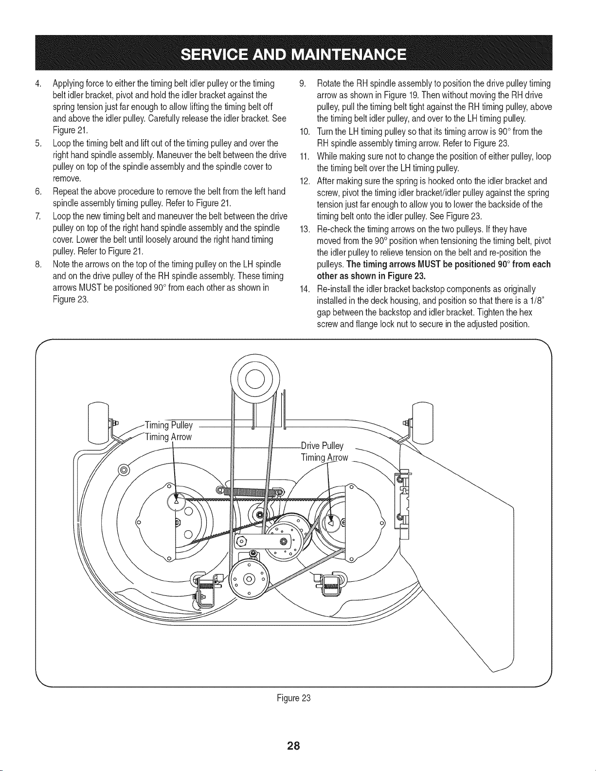
4. Applyingforceto eitherthetimingbelt idlerpulleyor thetiming
belt idlerbracket,pivotand holdtheidlerbracketagainstthe
springtensionjust farenoughto allowliftingthe timingbeltoff
andabovethe idler pulley.Carefullyreleasethe idler bracket.See
Figure21.
5. Loopthe timingbeltandlift out of the timingpulleyandoverthe
righthandspindleassembly.Maneuverthe belt betweenthe drive
pulleyontop of the spindleassemblyandthe spindlecoverto
remove.
6. Repeattheaboveprocedureto removethe beltfromthe left hand
spindleassemblytimingpulley.Referto Figure21.
7. Loopthe newtimingbeltand maneuverthe belt betweenthe drive
pulleyontop of the righthandspindleassemblyandthe spindle
cover.Lowerthe belt until looselyaroundthe right handtiming
pulley.Referto Figure21.
8. Notethe arrowson thetop of the timingpulleyonthe LHspindle
andonthe drivepulleyof the RHspindleassembly.Thesetiming
arrowsMUSTbe positioned90o fromeach otheras shownin
Figure23.
9. Rotatethe RHspindleassemblyto positionthedrive pulleytiming
arrowas shownin Figure19.Then withoutmovingthe RHdrive
pulley,pullthe timingbelt tightagainstthe RHtimingpulley,above
the timingbeltidlerpulley,andover to the LHtimingpulley.
10. Turnthe LHtiming pulleysothat its timingarrowis 900from the
RHspindleassemblytiming arrow.Referto Figure23.
11. Whilemakingsure notto changethe positionof either pulley,loop
the timingbeltoverthe LH timingpulley.
12. After makingsurethe springis hookedonto the idlerbracketand
screw,pivotthetimingidlerbracket!idlerpulleyagainstthe spring
tensionjustfar enoughto allowyouto lowerthe backsideof the
timingbeltonto theidlerpulley.SeeFigure23.
13. Re-checkthe timingarrowson the two pulleys.Iftheyhave
movedfromthe900positionwhentensioningthe timing belt, pivot
the idlerpulleyto relievetensionon the beltand re-positionthe
pulleys.The timing arrows MUSTbe positioned900from each
other as shownin Figure23.
14. Re-installthe idlerbracketbackstopcomponentsas originally
installedin thedeck housing,andpositionso thatthereis a 1/8"
gap betweenthe backstopandidlerbracket.Tightenthe hex
screwandflangelocknut to securein theadjustedposition.
Pulley
Arrow
@
Pulley
TimingArrow
Figure23
28
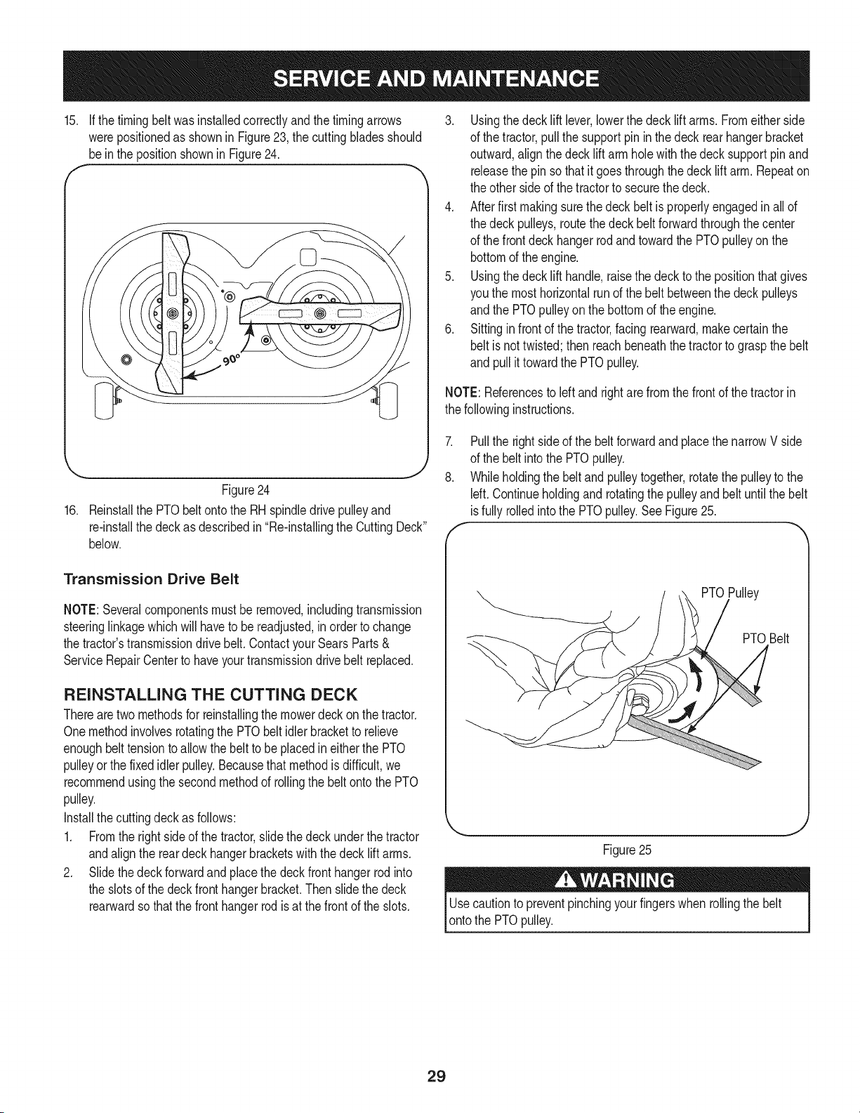
15. If thetiming beltwas installedcorrectlyand thetimingarrows
werepositionedas shownin Figure23, the cuttingbladesshould
bein the positionshownin Figure24.
-.. J
Figure24
16. Reinstallthe PTObeltontothe RHspindledrivepulleyand
re-installthe deckas describedin"Re-installingthe CuttingDeck"
below.
Transmission Drive Belt
NOTE:Severalcomponentsmustbe removed,includingtransmission
steeringlinkagewhichwill haveto be readjusted,inorderto change
the tractor'stransmissiondrivebelt.ContactyourSearsParts&
ServiceRepairCenterto haveyourtransmissiondrive belt replaced.
REINSTALLING THE CUTTING DECK
Therearetwomethodsfor reinstallingthemowerdeckon thetractor.
Onemethodinvolvesrotatingthe PTObelt idlerbracketto relieve
enoughbelttensionto allowthe belt to beplacedin eitherthe PTO
pulleyor the fixed idler pulley.Becausethat methodis difficult,we
recommendusingthe secondmethodof rollingthe beltonto the PTO
pulley.
Installthecuttingdeckas follows:
1. Fromthe rightside of the tractor,slide thedeckunderthetractor
andalignthe reardeckhangerbracketswith thedecklift arms.
2. Slidethedeckforwardandplacethe deckfronthangerrodinto
the slotsof the deckfronthangerbracket.Thenslidethe deck
rearwardso that thefront hangerrodis at thefrontof the slots.
3. Usingthedecklift lever,lowerthe deck lift arms.Fromeitherside
of the tractor,pullthe supportpinin the deckrearhangerbracket
outward,align the deck lift arm hole withthe decksupportpinand
releasethe pin so that it goesthroughthedeck lift arm. Repeaton
the otherside of thetractorto securethe deck.
4. Afterfirst makingsurethe deckbeltis properlyengagedin all of
the deckpulleys,routethe deck beltforwardthroughthe center
of the frontdeckhangerrodandtowardthe PTOpulleyon the
bottomof the engine.
5. Usingthedecklift handle,raisethe deckto the positionthatgives
you the mosthorizontalrunof the belt betweenthe deckpulleys
andthe PTOpulleyon the bottomof the engine.
6. Sittinginfrontof the tractor,facingrearward,make certainthe
beltis not twisted;thenreachbeneaththe tractorto graspthe belt
and pullit towardthe PTOpulley.
NOTE:Referencesto leftand rightare fromthe front of the tractorin
the followinginstructions.
7.
8.
Pullthe rightsideof the beltforwardand placethe narrowV side
of the belt intothe PTOpulley.
Whileholdingthe belt andpulleytogether,rotatethe pulleyto the
Idt. Continueholdingand rotatingthe pulleyandbelt untilthe belt
isfully rolledintothe PTOpulley.SeeFigure25.
PTOPulley
PTOBelt
J
Figure25
Usecautionto preventpinchingyourfingerswhen rollingthe belt
ontothe PTOpulley.
29

Neverstorelawntractorwithfuel intankindoorsor in poorly
ventilatedareaswherefuel fumesmayreachan openflame,spark,
or pilot lightas ona furnace,water heater,clothesdryer,or gas
appliance.
PREPARING THE ENGINE
iMPORTANT:Fuelleftinthe fueltankduringwarmweatherdeterio-
ratesandwillcauseseriousstartingproblems.
Gasolineisa toxic substance.Disposeof gasolineproperly.Contact
your localauthoritiesfor approveddisposalmethods.
To preventgumdepositsfrom forminginsidethe engine'scarburetor
andcausingpossiblemalfunctionof theengine,the fuelsystemmust
be eithercompletelyemptied,or the gasolinemustbetreatedwitha
stabilizerto preventdeterioration.
1. Ifusinga fuel stabilizer:
• Readthe productmanufacturer'sinstructionsandrecommenda-
tions.
• Addto clean,freshgasolinethe correctamountof stabilizerfor
the capacityof the fuel system.
• Fillthe fueltankwithtreatedfuel andrunthe enginefor 2-3
minutesto get stabilizedfuel intothe carburetor.
2. Ifemptyingthe fuel system:
• Donot drainfuelwhenthe engineis hot.Allowthe engine
adequatetime to cool. Drainfuelinto anapprovedcontainer
outdoors,awayfrom open flame.
• Drainany largevolumeof fuel from thetank by disconnectingthe
fuel linefromthe in-linefuelfilter nearthe engine.
Gasolineis extremelyflammableandcan beexplosiveundercertain
conditions.Draingasolinebeforestoringthe equipmentfor extended
periods.Drainfuelonly intoan approvedcontaineroutdoors,away
fromanopenflame.Allow engineto cool.Extinguishcigarettes,
cigars,pipes,andothersourcesof ignitionpriorto drainingfuel.
Storegasolinein an approvedcontainerin safelocation.
• Reconnectthe fuel lineandrunthe engineuntil it startsto falter,
then usethe choketo keepthe enginerunninguntil allfuel inthe
carburetorhas beenexhausted.
• Againdisconnectthefuel lineanddrainany remaininggasoline
fromthe system.
3. Removethe spark plugandpourone(1)ounceof engineoil
throughthe sparkplugholeintothe cylinder.Crankthe engine
severaltimesto distributethe oil. Replacethe spark plug.
PREPARING THE LAWN TRACTOR
• Cleanandlubricatetractorthoroughlyas describedinthe lubrica-
tion instructions.
• Donot usea pressurewasheror gardenhoseto cleanyour unit.
Store mowerin a dry,cleanarea. Do notstorenextto corrosive
materials,suchas fertilizer.
30
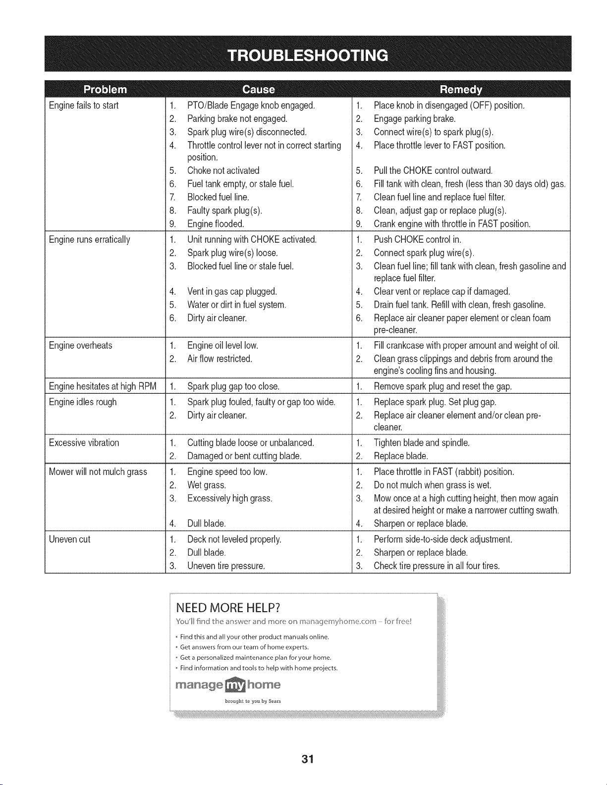
Enginefailsto start
Enginerunserratically
1. PTO/BladeEngageknobengaged.
2. Parkingbrakenotengaged.
3. Sparkplugwire(s)disconnected.
4. Throttlecontrollevernot incorrectstarting
position.
5. Chokenotactivated
6. Fueltankempty,or stale fuel.
7. Blockedfuel line.
8. Faultysparkplug(s).
9. Engineflooded.
1. Unitrunningwith CHOKEactivated.
2. Sparkplugwire(s)loose.
3. Blockedfuel line or stalefuel.
4. Ventingas cap plugged.
5. Wateror dirt in fuel system.
6. Dirtyair cleaner.
Engineoverheats 1. Engineoil levellow. 1.
2. Airflowrestricted. 2.
Enginehesitatesat high RPM 1. Sparkpluggaptoo close. 1.
Engineidles rough 1. Sparkplugfouled,faultyor gaptoo wide. 1.
2. Dirtyair cleaner. 2.
Excessivevibration
Mowerwill not mulchgrass
Unevencut
1. Cuttingbladelooseor unbalanced.
2. Damagedor bent cuttingblade.
1. Enginespeedtoo low.
2. Wetgrass.
3. Excessivelyhighgrass.
4. Dullblade.
1. Decknot leveledproperly.
2. Dullblade.
3. Uneventire pressure.
1. Placeknobindisengaged(OFF)position.
2. Engageparkingbrake.
3. Connectwire(s)to sparkplug(s).
4. Placethrottleleverto FASTposition.
5. Pullthe CHOKEcontroloutward.
6. Filltankwithclean,fresh(lessthan 30daysold)gas.
7. Cleanfuel lineand replacefuelfilter.
8. Clean,adjustgapor replaceplug(s).
9. Crankenginewiththrottlein FASTposition.
1. PushCHOKEcontrolin.
2. Connectsparkplugwire(s).
3. Cleanfuel line; fill tankwithclean,freshgasolineand
replacefuel filter.
4. Clearventor replacecap if damaged.
5. Drainfueltank. Refillwithclean,freshgasoline.
6. Replaceair cleanerpaper elementor cleanfoam
pre-cleaner.
Fillcrankcasewithproperamountandweightof oil.
Cleangrass clippingsand debrisfromaroundthe
engine'scoolingfinsandhousing.
Removespark plug and resetthe gap.
Replacesparkplug.Set pluggap.
Replaceair cleanerelementand/orcleanpre-
cleaner.
1. Tightenbladeandspindle.
2. Replaceblade.
1. Placethrottlein FAST(rabbit)position.
2. Do notmulchwhen grassis wet.
3. Mowonceat a highcuttingheight,then mowagain
at desiredheightor makea narrowercuttingswath.
4. Sharpenor replaceblade.
1. Performside-to-sidedeckadjustment.
2. Sharpenor replaceblade.
3. Checktire pressureinall fourtires.
NEED MORE HELP?
Youll fkld t_e answe_ _"ct mo_e o_ maoage_nyl]o_ne co_n - br kee!
Find this and all your other product manuals online.
Get answers from our team of home experts.
,, Get a personalized maintenance plan for your home.
,, Find information and tools to help with home projects.
maoage _ home
b_*oug_t t_ _'ou by Sea_'s
31
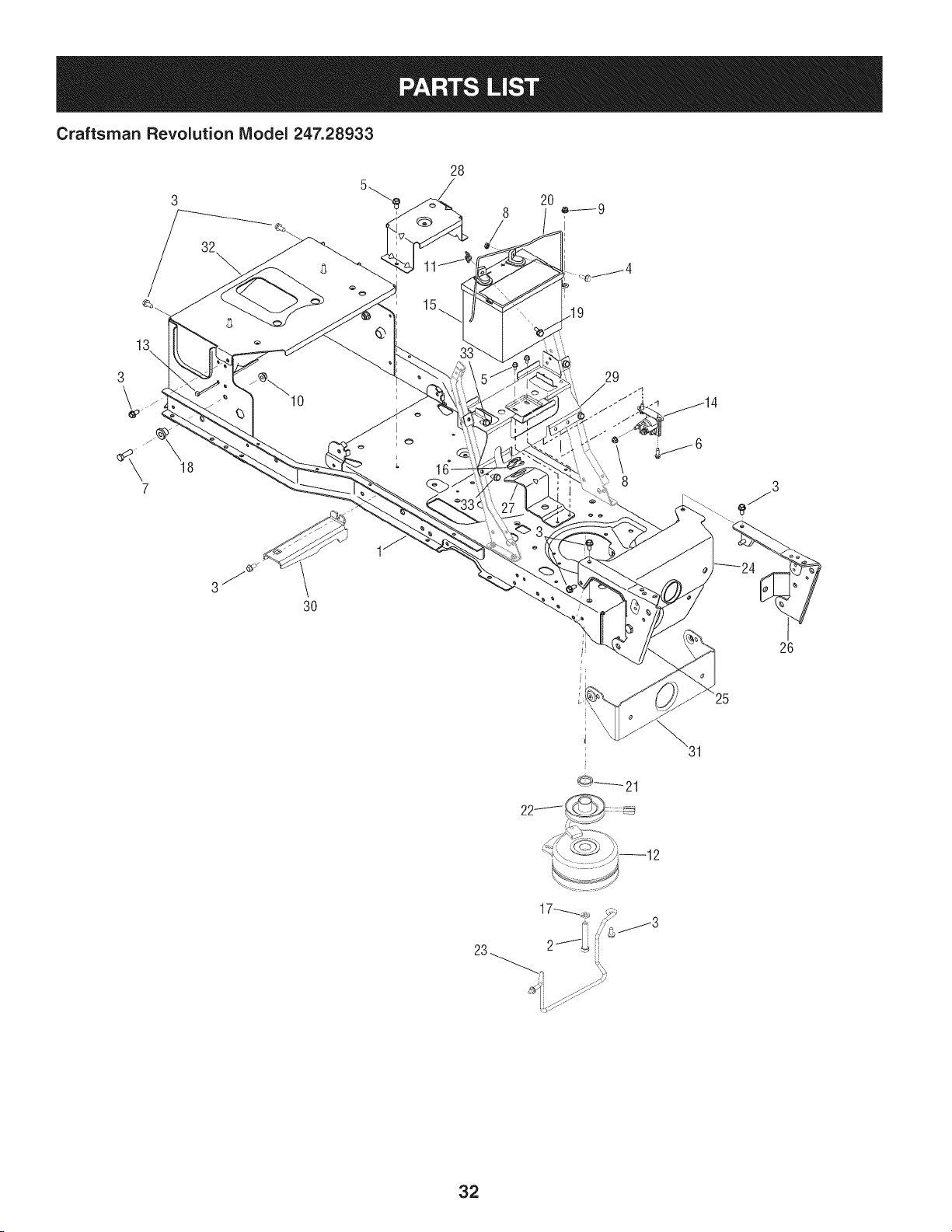
Craftsman Revolution Model 247.28933
28
3
\
32
\
13
3:
19
29
7
3O
26
25
0------_21
23
32
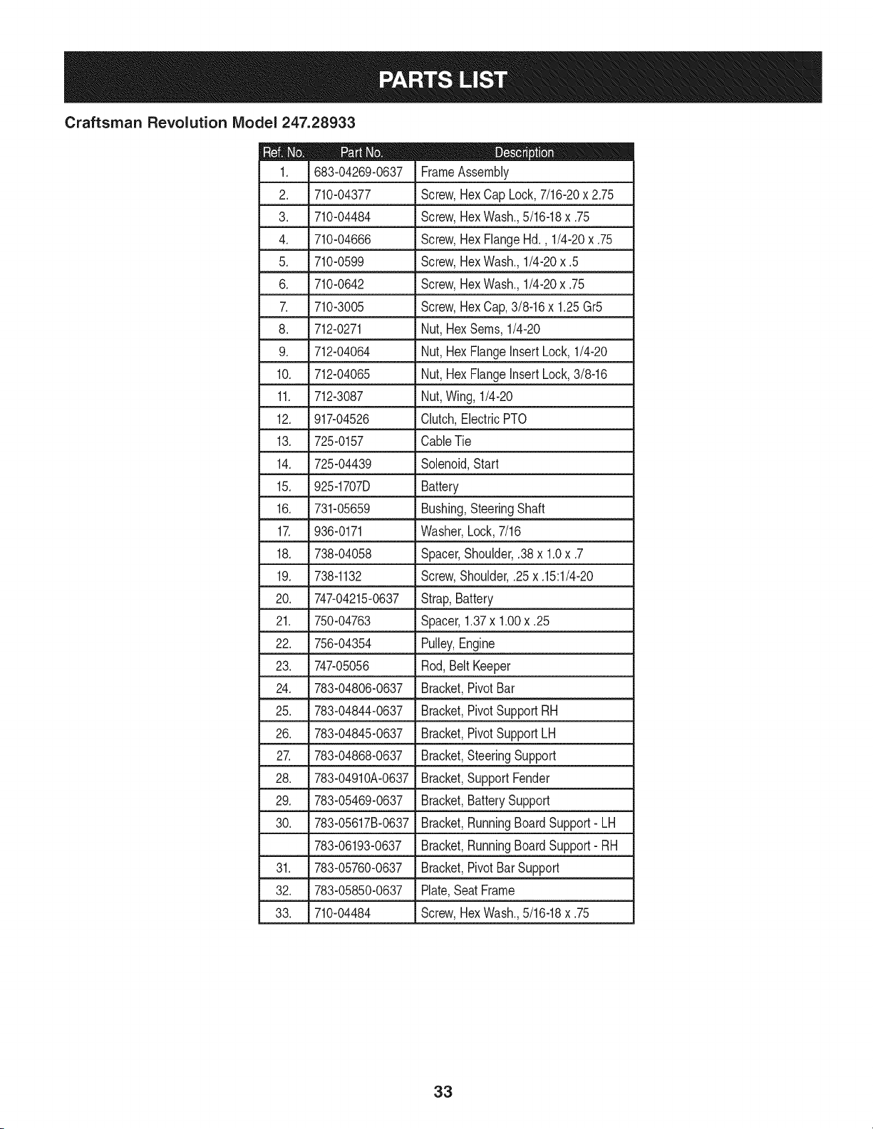
Craftsman Revolution IViodel 247.28933
D = O O
683-04269-0637 FrameAssembly
2. 710-04377 Screw,Hex Cap Lock,7/16-20x 2.75
3. 710-04484 Screw,Hex Wash.,5/16-18x .75
4. 710-04666 Screw,Hex FlangeHd., 1/4-20x .75
5. 710-0599 Screw,Hex Wash.,1/4-20x .5
6. 710-0642 Screw,Hex Wash.,1/4-20x .75
7. 710-3005 Screw,Hex Cap,3/8-16x 1.25Gr5
8. 712-0271 Nut, HexSeres,1/4-20
9. 712-04064 Nut, HexFlangeInsertLock,1/4-20
10. 712-04065 Nut, HexFlangeinsertLock,3/8-16
11. 712-3087 Nut,Wing,1/4-20
12. 917-04526 Clutch,ElectricPTO
13. 725-0157 CableTie
14. 725-04439 Solenoid,Start
15. 925-1707D Battery
16. 731-05659 Bushing,SteeringShaft
17. 936-0171 Washer,Lock,7/16
18. 738-04058 Spacer,Shoulder,.38x 1.0x .7
19. 738-1132 Screw,Shoulder,.25x .15:1/4-20
20. 747-04215-0637 Strap,Battery
21. 750-04763 Spacer,1.37x 1.00x .25
22. 756-04354 Pulley,Engine
23. 747-05056 Rod,BeltKeeper
24. 783-04806-0637 Bracket,PivotBar
25. 783-04844-0637 Bracket,PivotSupportRH
26. 783-04845-0637 Bracket,PivotSupportLH
27. 783-04868-0637 Bracket,SteeringSupport
28. 783-04910A-0637 Bracket,SupportFender
29. 783-05469-0637 Bracket,BatterySupport
30. 783-05617B-0637 Bracket,RunningBoard Support- LH
783-06193-0637 Bracket,RunningBoard Support- RH
31. 783-05760-0637 Bracket,PivotBarSupport
32. 783-05850-0637 Plate,SeatFrame
33. 710-04484 Screw,Hex Wash.,5/16-18x .75
33
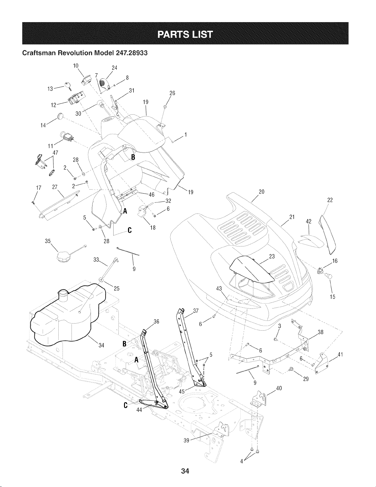
Craftsman Revolution IViodel 247.28933
17
/
10 24
\
\
35 28
9
19
\
18
\
\
\
\
\,
\
\
2O
21
42
22
/
/
15
C
36
5
9
29
/
/41
34

Craftsman Revolution IViodel 247.28933
710-0192 Screw,TrussHd. Mach.,10-24x .375
2. 710-0599 Screw,HexWash,1/4-20x .5
3. 710-0604A Screw,HexWash,5/16-18x .625
4. 710-04484 Screw,HexWash,5/16-18x .75
5. 710-0642 Screw,HexWash,1/4-20x .75
6. 710-0895 Screw,HexWash,1/4-15x .75
7. 710-3217 Screw,TrussHd.Mach.,#8-32x .375
8. 712-0142 Nut,Hex,8-32
9. 725-0157 Tie, Cable
10. 925-04022B Meter,Indicator/ServiceMonitor
11. 925-04174 Switch,PTO
L
12. 925-04227B Switch,Ingition/Moduie
13. 925-1745A Key,Ignition,w/Plastic Cover
925-1744A Key,Ignition,w/o PlasticCover
14. 720-3025 Plug
15. 925-0963 Bulb,12VLight
16. 925-1649 Receptacle,Light
17. 726-3046 Clip,Ratchet
18. 731-04213 Lever,DashBrake
19. 731-05406 Panel,Dash
20. 731-06830 Hood
21. 731-05935 Plenum,Hood
22. 731-05525 Lens,HeadLightLH
23. 731-05526 Lens,HeadLightRH
24. 731-1857 Knob,ThrottleControl
25. 935-0149 Bushing,FuelTank
D = O e
735-0271A Bumper
27. 735-04076 Net,Storage
28. 936-0463 Washer,Flat,.25 x .63x .0515
29. 738-04091A Screw,Shoulder,.43x .29:TT5/16-18
30. 746-04132 Cable,ChokeControl
31. 746-1100 Cable,ThrottleControl
32. 747-1155 Rod,BrakeLock Pivot
33. 751-10442 Fitting,FuelPickUp
34. 751-10692 Tank,Fuel
35. 751-10703 Cap,FuelTank
36. 783-04285F-0637 Support,Dash,R.H.
37. 783-04323F-0637 Support,Dash,L.H.
38. 683-04536 Bracket,HoodPivot
39. 783-04840-0637 Bracket,HoodPivot RH
40. 783-04841-0637 Bracket,HoodPivot LH
41. 783-05162-0637 Bracket,HoodSupport
42. 777X42426 Label,Reflector
43. 777X42427 Label,Reflector
44. 783-05140-0637 Brkt.,Strg. Support,RH
45. 783-04798-0637 Brkt.,Strg. Support,LH
46. 783-04799-0637 Brkt.,Support,UpperStrg.
47. 725-2003 12VPowerReceptacle
-- 925-04375A Harness,MainWire(IncludesFuse)
-- 925-1381 Fuse,20 Amp
-- 937-04050 GreaseGunKit
35
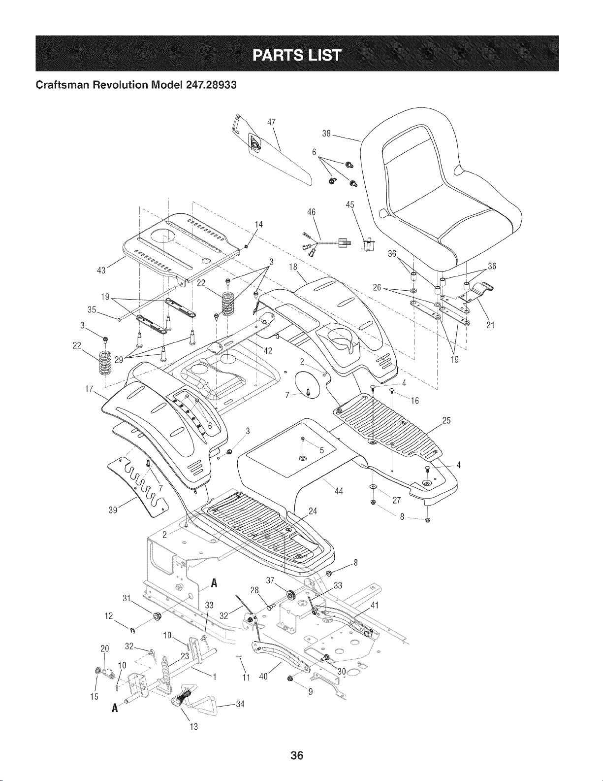
Craftsman Revolution IViodel 247.28933
45
/
24
19
25
21
15
12
11
28
36

Craftsman Revolution IViodel 247.28933
|= o o
647-04095A-0637 Shaft, Lift
2. 710-04187 Screw,HexWashHd.H/L, 1/4-15x .5
3. 710-04484 Screw,Hd.Tapp,5/16-18x .75
4. 710-0451 Screw,Carriage,5/16-18x 75
5. 710-0599 Screw,Hd.Tapp,1/4-20x .5
6. 710-1260A Screw,Hd.Tapp,5/16-18x .75
7. 710-0895 Screw,Hd.Tapp,1/4-15x .75
8. _ 712-04063 _ Nut,HexFlangeinsertLock,5/16-18
9. 712-04065 Nut,HexFlangeinsertLock,3/8-16
10. 914-0104 Pin,InternalCotter
11. 914-0111 Pin,Cotter,3/32 x 1.0
12. 716-0106A E-ring,.625Shaft
13. 720-0311 Grip, Handle
14. 726-0135 Nut,Speed,.3125Dia.
15. 726-0221 Nut,Speed,.5
16. 726-3046 Clip,Ratchet
17. 731-06836 Cover,RearFenderRH
18. 731-06835 Cover,RearFenderLH
19. 731-06208 Spacer,SeatAdjust
20. 732-04459 Spring,Lift HandleTorsion
21. 732-04491 Spring,SeatAdjust
22. 732-04508 Spring,Compress.,1.71x 3.25x .23
23. 732-0826A Spring,Extension,.865x 4.68
24. 735-04078A Pad,FootRH
735-04109
26. 936-0192
27. 736-3078
28. 738o0138A
29. 938-0373
30. 738-04130
31. 941-0225
D = O O
Pad,Foot LH
Washer,Fiat, .535x .93x .09
Washer,Fiat, .344x 1.0x .063 HT
Bolt,Shoulder,.496x 2.5:3/8-16
Bolt,Shoulder,.496x 1.525:3/8-16
Bolt,Shoulder,.625x .175:3/8-16
Bearing,Hex Flange,
32. J 946-04546 J Cable,Lift, 16.64Lg
33. 946-04436 Cable,Lift, 16.64Lg
34. 747-04701 Handle,Lift
35. 747-04821 Rod,Seat,5/16x 11.62
36. 750-04945 Spacer,.51x .75x 1.0
37. 756-04331 Pulley,Roller
38. 757-04104 Seat,HighBack
39. 783-04977A-0637 Plate,DeckLift index
40. 783-04494B-0637 Arm,DeckLift RH
41. 783-04711B-0637 Arm,DeckLift LH
42. 783-05816-0637 Bracket,Seat Pivot
43. 783-05817-0637 Plate,SeatMounting
44. 783-05865A-0637 Fender,Rear
45. 925-04040 Switch,Seat
46. 725-04658 Harness,Seat SwitchJumper
47. 757-04040 Arm Rest,Seat
37
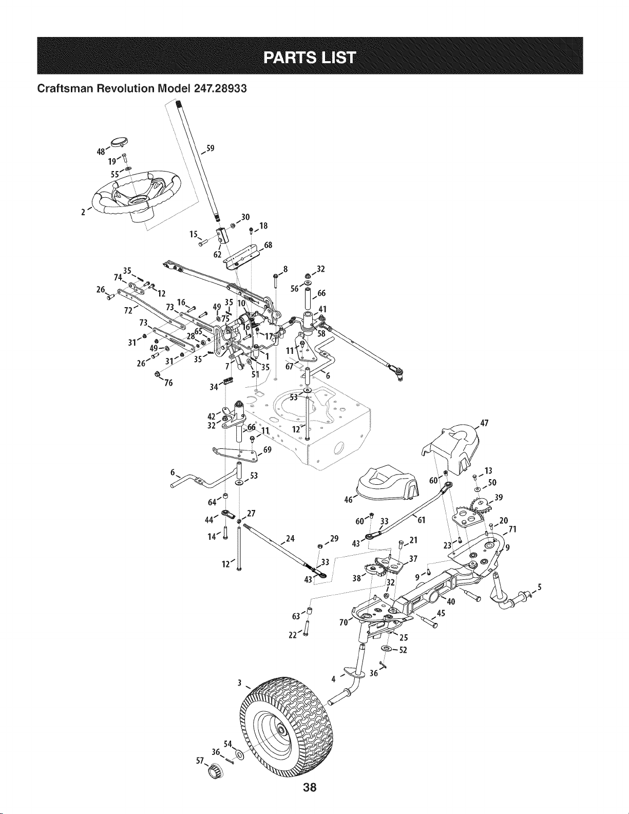
Craftsman Revolution IViodel247.28933
62
26
_..18
68
12"
/
63"_
22t_ 7
/?
47
38
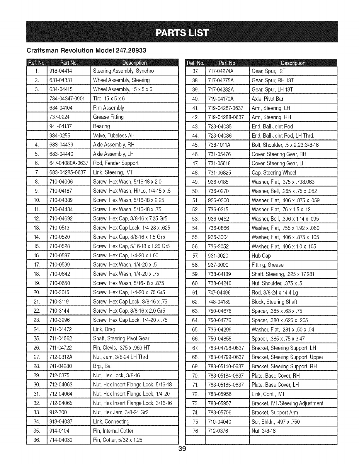
Craftsman Revolution Model 247.28933
|- 0 e
918-04414 SteeringAssembly,Synchro
2. 631-04331 WheelAssembly,Steering
3. 634-04415 WheelAssembly,15x 5 x 6
734-04347-0901 Tire, 15x 5 x 6
634-04104 RimAssembly
737-0224 GreaseFitting
941-04137 Bearing
934-0255 Valve,TubelessAir
4. 683-04439 Axle Assembly,RH
5. 683-04440 Axle Assembly,LH
6. J 647-04080A-0637 Rod,FenderSupport
7. 683-04285-0637 Link,Steering,IVT
8. 710-04006 Screw,HexWash,5/16-18x 2.0
9. 710-04187 Screw,HexWash,Hi/Lo, 1/4-15x .5
10. 710-04389 Screw,HexWash,5/16-18x 2.25
11. 710-04484 Screw,HexWash,5/16-18x .75
12. 710-04692 Screw,HexCap,3/8-16x 7.25Gr5
13. 710-0513 Screw,Hex CapLock, 1/4-28x .625
14. _710-0520 _ Screw,Hex Cap,3/8-16x 1.5Gr5
15. 710-0528 Screw,Hex Cap,5/16-18x 1.25Gr5
16. 710-0597 Screw,Hex Cap,1/4-20x 1.00
17. 710-0599 Screw,HexWash,1/4-20x .5
18. 710-0642 Screw,HexWash,1/4-20x .75
19. 710-0650 Screw,HexWash,5/16-18x .875
20. 710-3015 Screw,Hex Cap,1/4-20x .75 Gr5
21. 710-3119 Screw,Hex CapLock,3/8-16x .75
22. _ 710-3144 , Screw,HexCap,3/8-16x 2.0 Gr5
23. 710-3296 Screw,Hex CapLock, 1/4-20x .75
24. 711-04472 Link,Drag
25. ,711-04562 L Shaft,SteeringPivotGear
26. 711-04722 Pin,Clevis,.375x .969HT
27. 712-0312A Nut,Jam,3/8-24 LHThrd
28. 741-04280 Brg.,Ball
29. 712-0375 Nut,HexLock,3/8-16
30. .712-04063 _ Nut,HexInsertFlangeLock,5/16-18
31. 712-04064 Nut,HexInsertFlangeLock,1/4-20
32. 712-04065 Nut,HexInsertFlangeLock,3/16-16
33. 912-3001 Nut,HexJam, 3/8-24Gr2
34. 913-04037 Link,Connecting
35. 914-0104 Pin,InternalCotter
36. 714-04039 Pin,Cotter,5/32 x 1.25
m = W O
717-04274A Gear,Spur, 12T
38. 717-04275A Gear,Spur,RH 13T
39. 717-04282A Gear,Spur,LH 13T
40. 719-04170A Axle,PivotBar
41. 719-04287-0637 Arm, Steering,LH
42. 719-04288-0637 Arm,Steering,RH
43. 723-04035 End,Ball Joint Rod
44. 723-04036 End,Ball Joint Rod, LHThrd.
45. 738-1011A Bolt,Shoulder,.5x 2.23:3/8-16
46. 731-05476 Cover,SteeringGear,RH
47. 731-05618 Cover,SteeringGear,LH
48. 731-06825 Cap,SteeringWheel
49. 936-0185 Washer,Fiat,.375x .738.063
50. 736-0270 Washer,Bell,.265x .75x .062
51. 936-0300 Washer,Fiat,.406x .875x .059
52. 736-0315 Washer,Fiat,.76x 1.5x .12
53. 936-0452 Washer,Bell,.396x 1.14x .095
54. 736-0866 Washer,Fiat,.755x 1.92x .060
55. 936-3004 Washer,Fiat,.406x .875x .105
56. 736-3052 Washer,Fiat,.406x 1.0x .105
57. 931-3020 HubCap
58. 937-3000 Fitting,Grease
59. 738-04189 Shaft,Steering,.625x 17.281
60. 738-04240 Nut,Shoulder,.375x .5
61. 747-04496 Rod,3/8-24x 14.4Lg
62. 748-04139 Block,SteeringShaft
63. 750-04676 Spacer,.385x .63 x .75
64. 750-04776 Spacer,.380x .625x .265
65. 736-04299 Washer,Fiat,.281x .50 x .04
66. 750-04855 Spacer,.385x .75x 3.47
67. 783-04798-0637 Bracket,SteeringSupport,LH
68. 783-04799-0637 Bracket,SteeringSupport,Upper
69. 783-05140-0637 Bracket,SteeringSupport,RH
70. 783-05184-0637 Plate,BaseCover,RH
71. 783-05185-0637 Plate,BaseCover,LH
72. 783-05956 Link,Cont.,IVT
73. 783-05957 Bracket,IVT/SteeringAdjustment
74. 783-05706 Bracket,SupportArm
75 710-04040 Scr,Shldr.,.497x .750
76 712-0376 Nut,3/8-16
39
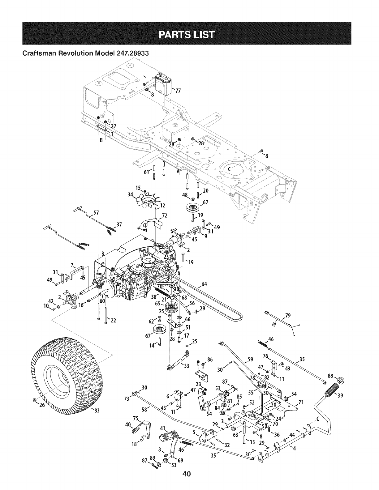
Craftsman Revolution IViodel 247.28933
3O
54
54
_53
4O
35
44
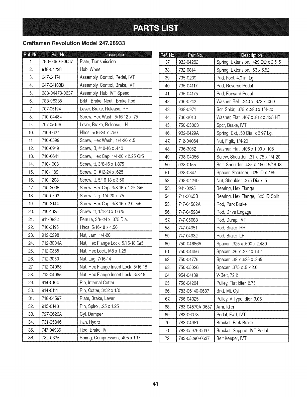
Craftsman Revolution IViodel 247.28933
783-04904-0637
2. 918-04228
3. 647-04174
4. 647-04103B
5. 683-04473-0637
6. 783-06385
707-05194
8. 710-04484
9. 707-05196
10. 710-0627
11. 710-0599
12. 710-0919
13. 710-0641
14. 710-1008
D = O O
Plate,Transmission
Hub,Wheel
Assembly,Control,Pedal,IVT
Assembly,Control,Brake,IVT
Assembly,Hub, IVT Speed
Brkt.,Brake,Neut.,BrakeRod
Lever,Brake,Release,RH
Screw,Hex Wash,5/16-12x .75
Lever,Brake,Release,LH
Hhcs,5/16-24x .750
Screw,Hex Wash.,1/4-20x .5
Screw,B, #10-16x .440
Screw,Hex Cap, 1/4-20x 2.25 Gr5
Screw,tt, 3/8-16x 1.875
710-1189 Screw,C, #12-24x.625
15.
16. 710-1208 Screw,tt, 5/16-18x 3.50
17. 710-3005 Screw,HexCap,3/8-16x 1.25Gr5
18. 710-0703 Screw,Crg,1/4-20x .75
19. 710-3144 Screw,HexCap,3/8-16x 2.0 Gr5
20. 710-1325 Screw,tt, 1/4-20x 1.625
21. 911-0832 Ferrule,3/8-24 x .375Dia.
22. 710-3195 Hhcs,5/16-18x 4.50
23. 912-0298
24. 712-3004A
25. 712-0365
26. 712-3050
2_ 712-04063
28. 712-04065
29. 914-0104
30. 914-0111
Nut,Jam, 1/4-20
Nut, HexFlangeLock,5/16-18Gr5
Nut, HexLock, M8x 1.25
Nut, Lug,7/16-14
Nut, HexFlangeInsertLock,5/16-18
Nut, HexFlangeInsertLock,3/8-16
Pin, InternalCotter
Pin,Cotter,3/32 x 1/0
31. 718-04597 Plate,Brake,Lever
32. 915-0143 Pin,Spirol,.25 x 1.25
33. 727-0626A Cyl, Damper
34. 731-05846 Fan,Hydro
35. 747-04935 Rod,Brake,IVT
36. 732-0335 Spring,Compression,.405x 1.17
m = _ 0
932-04262 Spring,Extension,.429OD x 2.515
38. 732-0814 Spring,Extension,.56 x 5.52
39. 735-0239 Pad,Foot,4.0 in. Lg
40. 735-04117 Pad,ReversePedal
41. 735-04175 Pad,ForwardPedal
42. 736-0242 Washer,Bell,.340x .872x .060
43. 938-0974 Scr,Shldr,.375x .380x 1/4-20
44. 736-3010 Washer,Flat,.407x .812x .135HT
45. 750-05063 Spcr,Brake,IVT
46. 932-0429A Spring,Ext, .50 Dia.x 3.97Lg.
47. 712-04064 Nut,FIglk,1/4-20
48. 736-3052 Washer,Flat,.406x 1.00x .105
49. 738-04356 Screw,Shoulder,.31x .75x 1/4-20
50. 938-0155 Bolt,Shoulder,.435x .160: 5/16-18
51. 938-0347 Spacer,Shoulder,.625ID x .169
52. 738-04240 Nut,Shoulder,.375Dia x .5
53. 941-0225 Bearing,HexFlange
54. 741-3065B Bearing,HexFlange,.625ID Split
55. 747-04562A Rod,ParkBrake
56. 747-04598A Rod,DriveEngage
57. 747-05088 Rod,Dump,IVT
58. 747-04951 Rod,Brake RH
59. 747-04932 Rod,Brake LH
60. 750-04686A Spacer,.325x .500x 2.480
61. 750-04456 Spacer,.26x .372x 1.42
62. 750-04776 Spacer,.38x .625x .265
63. 750-05026 Spacer,.375x .5 x 2.0
64. 954-04139 V-Belt,72.2
65. 756-04224 Pulley,Flat Idler,2.75
66. 783-06140-0637 Brkt,Mt, Cyl
67. 756-04325 Pulley,V Type Idler,3.06
68. 783-04570A-0637 Arm,Idler
69. 783-06373 Pedal,Fwd,IVT
70. 783-04981 Bracket,ParkBrake
71. 783-05976-0637 Bracket,Support,IVT Pedal
72. 783-05290-0637 BeltKeeper,IVT
41
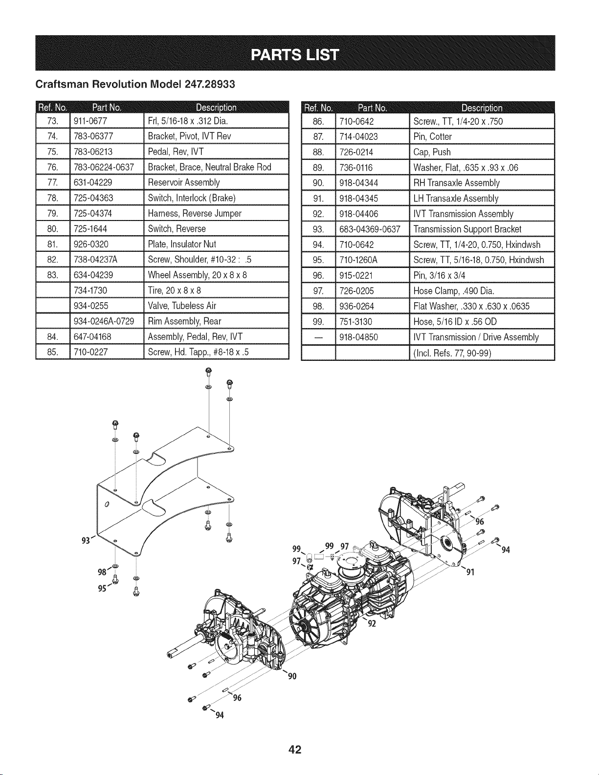
Craftsman Revolution IViodel 247.28933
D = O
911-0677 FrI,5/16-18x .312Dia.
74. 783-06377 Bracket,Pivot,IVT Rev
75. 783-06213 Pedal,Rev,IVT
76. 783-06224-0637 Bracket,Brace,NeutralBrakeRod
77. 631-04229 ReservoirAssembly
78. 725-04363 Switch,Interlock(Brake)
79. 725-04374 Harness,ReverseJumper
80. 725-1644 Switch,Reverse
81. 926-0320 Plate,InsulatorNut
82. 738-04237A Screw,Shoulder,#10-32:.5
83. 634-04239 WheelAssembly,20 x 8 x 8
734-1730 Tire,20 x 8 x 8
934-0255 Valve,TubelessAir
934-0246A-0729 RimAssembly,Rear
84. 647-04168 Assembly,Pedal,Rev,IVT
85. 710-0227 Screw,Hd.lapp., #8-18x .5
m = O
710-0642 Screw.,TT, 1/4-20x .750
87. 714-04023 Pin,Cotter
88. 726-0214 Cap, Push
89. 736-0116 Washer,Fiat,.635x .93x .06
90. 918-04344 RHTransaxleAssembly
91. 918-04345
92. 918-04406
93. 683-04369-0637
94. 710-0642
95. 710-1260A
LHTransaxleAssembly
IVTTransmissionAssembly
TransmissionSupportBracket
Screw,TT, 1/4-20,0.750,Hxindwsh
Screw,TT,5/16-18,0.750,Hxindwsh
96. 915-0221
9_ 726-0205
98. 936-0264
99. 751-3130
-- 918-04850
Pin,3/16 x 3/4
HoseClamp,.490Dia.
FiatWasher,.330x .630x .0635
Hose,5/16 ID x .56 OD
IVTTransmission/ DriveAssembly
(Incl. Refs.77,90-99)
96
42
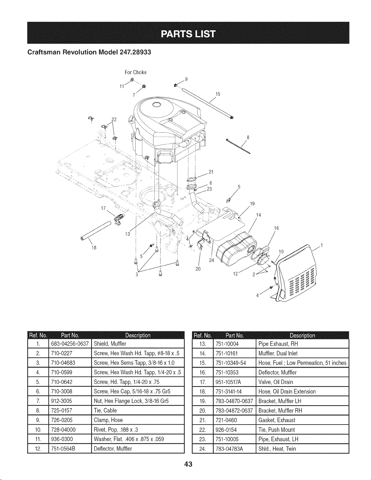
Craftsman Revolution Model 247.28933
22
0
15
I
17 :
18
5 /
/
20
8
14
16
m = O O
683-04256-0637 Shield,Muffler
2. 710-0227 Screw,HexWash Hd. Tapp,#8-18x .5
3. 710-04683 Screw,HexSeresTapp,3/8-16x 1.0
4. 710-0599 Screw,HexWash Hd. lapp, 1/4-20x .5
5. 710-0642 Screw,Hd. lapp, 1/4-20x .75
6. 710-3008 Screw,Hex Cap,5/16-18x .75Gr5
7. 912-3005 Nut, HexFlangeLock,3/8-16Gr5
8. 725-0157 Tie,Cable
9. 726-0205 Clamp,Hose
10. 728-04000 Rivet,Pop,.188x .3
11. J936-0300 . Washer,Fiat, .406x.875 x.059
12. 751-0564B Deflector,Muffler
D = O
751-10004 PipeExhaust,RH
14. 751-10161 Muffler,DualNet
15. 751-10349-54 Hose,Fuel; LowPermeation,51 inches
16. 751-10353 Deflector,Muffler
17. 951-10517A Valve,OilDrain
18. 751-3141-14 Hose,Oil DrainExtension
19. 783-04870-0637 Bracket,MufflerLH
20. 783-04872-0637 Bracket,MufflerRH
21. 721-0460 Gasket,Exhaust
22. 926-0154 Tie, PushMount
23. 751-10005 Pipe,Exhaust,LH
24. 783-04783A Shld.,Heat,Twin
43
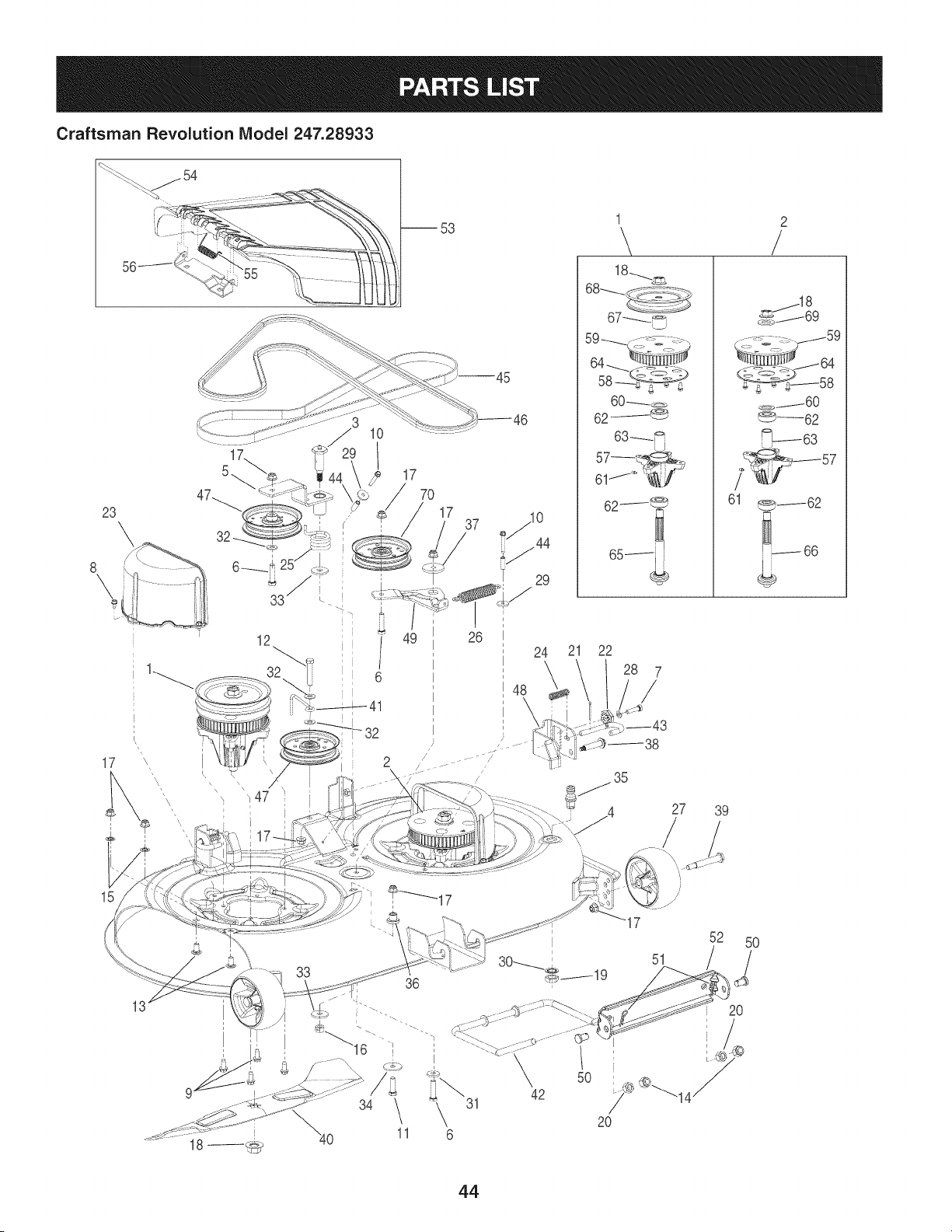
Craftsman Revolution Model 247.28933
23
\
8
\
17
®
21 22
1 2
\ /
18_
60 _D
62/_
<_.y_----60
_--62
_63
7_ 57
61 _62
66
27 39
15
31
6
5O
42
51
20
52 5O
/
20
44

Craftsman Revolution IViodel 247.28933
D = _
918-04512A SpindleAssembly- Drive
2. 918-04516 SpindleAssembly- Driven
3. 638-04012A BoltAssembly,Shoulder
4. 983-04379A-0721 DeckAssembly
5. 683-04425-0721 Bracket,Idler
6. 710-0520 Screw,HexCap,3/16-18x 1.5Gr5
7. 710-0528 Screw,HexCap,5/16-18x 1.25Gr5
8. 710-0599 Screw,HexWash.,1/4-20x .5
9. 710-04484 Screw,HexWash.,5/16-18x .75
10. 710-1325 Screw,HexWash.,1/4-20x 1.625
11. 710-3005 Screw,HexCap,3/8-16x 1.25Gr5
12. 710-3144 Screw,HexCap,3/8-16x 2.0Gr5
13. 710-3178 Screw,Carriage,3/8-16x .75
14. 912-0206 Nut,Hex,1/2-13Gr5
15. 712-0229 Nut,Push,3/8
16. 712-0290 Nut,HexLock,7/16-14
17. 712-04065 Nut,Hex FlangeInsert Lock,3/8-16
18. 712-0417A Nut,HexFlange,5/8-18
19. 912-0641 Nut,Hex,M16-1.5
20. 712-3083 Nut,HexInsertLock,1/2013
21. 914-0470 Pin,Cotter,1/8x 1.25
22. 917-04074 Gear,DeckAdjust
23. 731-06291A Cover,Belt
24. 932-0306A Spring,Compression,.531x 1.75
25. 732-04469 Spring,Torsion,1.10x 1.3
26. 732-0826A Spring,Extension,.865x 4.68
27. 734-04155 Wheel,Deck Ball,5.0
28. 936-0119 Washer,Lock,5/16
29. 936-0176 Washer,Fiat,.265x .938x .12
30. 736-0225 Washer,InternalToothLock,5/8
31. 736-0258 Washer,Fiat,.385x 1.0x .135
32. 936-0300 Washer,Fiat,.406x .875x .059
33. 736-0322 Washer,Fiat,.45x 1.38x .134
34. 936-3039 Washer,Fiat,.406x 2.5 x .164
35. 737-04003D Nozzle,DeckWash
m = O
938-0785 Spacer,Shoulder,1.38x .445x .36
37. 738-04162A Spacer,Shoulder,.884x .190
38. 738-04316 Bolt,Shoulder,.435x 1.76:5/16-24
39. 938-3056 Bolt,Shoulder,.496x 2.5:3/8-16
40. 942-04217 Blade,Timing2 in 1,22.0
41. 747-04530 Rod,BeltKeeper
42. 747-04863 Rod,DeckFrontHanger
43. 747-1116 Rod,DeckRelease
44. 750-0566A Spacer,.26 x .372x 1.03
45. 954-04167 Belt,Timing,.189T
46. 954-04185 V-Belt,TypeA x 89.24
47.
756-04129 Pulley,Idler,4.25 Dia
48. 783-05627-0637 Bracket,DeckHanger/AdjustLH
49. 783-05802-0637 Bracket,Idler
50. 911-0332 Pin,Clevis,.5 x .78
51. 914-04023 Pin,InternalCotter
52. 783-0720C-0637 Bracket,Front DeckRod
53. 631-04254 DeflectorAssembly,Chute
54. 711-04847A Pin,Hinge
55. 732-04372 Spring,Torsion,.44x 2.0
56. 783-05823 Bracket,ChuteMounting
57. 619-04199 Housing,Spindle
Screw,Tri-Plask,1/4-10x .625
Pulley,Timing,56T
Washer,Fiat, .793x 1.24x .06 HT
Fitting,Lube
Bearing,Ball
Spacer,.792x 1.06x 1.86
Plate,TimingPulley
Shaft,Spindle,5.46Long
Shaft,Spindle,4.44Long
Spacer,.735x 1.375xl.066
Pulley,Deck,Timing,6.67Dia
Washer,Fiat, .76x 1.5x .12
Pulley,Idler,3.50 Dia.
58. 710-04065
59. 913-04040A
60. 936-0287
61. 937-3000
62. 941-0919
63. 750-04936
64. 787-01520
65. 938-04292
66. 938-04291
67. 750-04724
68. 756-04372
69. 736-0315
70. 756-04280
45
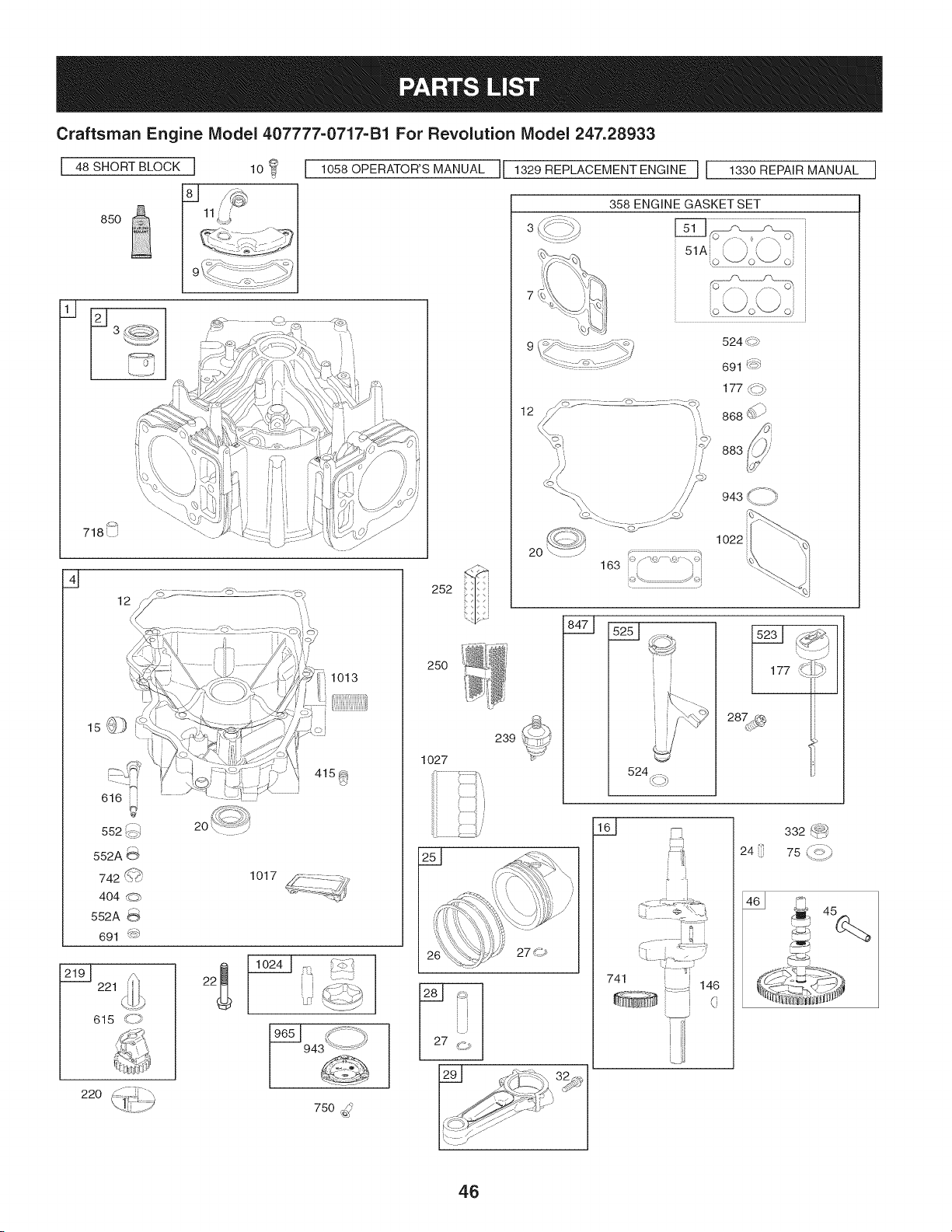
Craftsman Engine Model 407777=0717=B1 For Revolution Model 247.28933
I 48 SHORT BLOCK I
q
850
11L4
_ ...... i ¸
| ......
1058 OPERATOR'S MANUAL
616 i,
552 _,
552A
742 S(_
404
r--,
552A
691 s_
221
615 _=_
1013
i
i
1017 _Z_-_...... _._
7-
t_
7i
252
25O
1O27
2
220 (_))
1 ]
I[ 1329 REPLACEMENT ENGINE ] 1330 REPAIR MANUAL
iL
2O
C= 7:2_::::o ."3s
163 i'_/_ ..... \_"_i
943 \: j
1022
239
251 _
524 ,((::p)
F:::_[
"i • _•i"_
741 l i
::: ::::: 146
i (
24
332 f_@
/ _-_
75 y=i
D- 45
750 :,_
I_ _/Z_ I
46
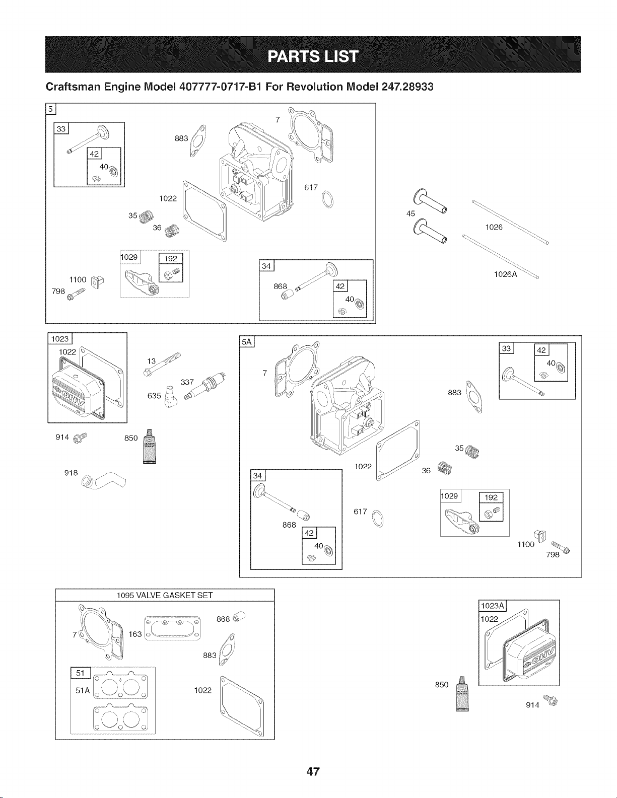
Craftsman Engine IViodel 407777-0717-B1 For Revolution IViodel 247.28933
883
1022
617
1026 _
"_
1026A ""_.'%
914 _ 850
918
635
337
868
1022
617
36
883
®
1022
85O
914 _@
47
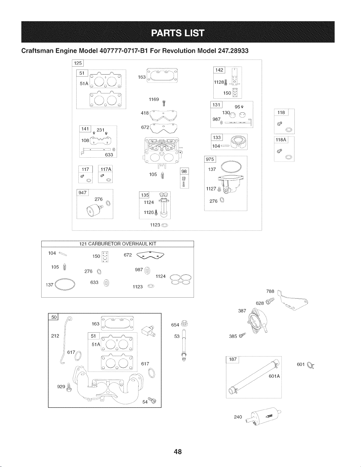
Craftsman Engine Model407777-0717=B1For Revolution Model 247.28933
108 _- _J_'_<"
\_ / \? i
633
163,£ /_._}
y
1169
418 <_ _ .... ,_...
672 \ _' )
_1128_ '_:
15o_,S
987
@
©i ©
276
lOS
1124
1126_
1123 _._
118A
J
137
212
929_
121 CARBURETOR OVERHAUL KIT
150 _ 672
o £j
276 _ 987 _h
\,5_'
1124
633
1123 _-_
_)/.o/ '.,% -\ _4
163
\_ J
°'" o\Jot, jd
617
s-%
654 <_-*_
53 ::bl
387
385 ¢_
601 _,%<
24O
48
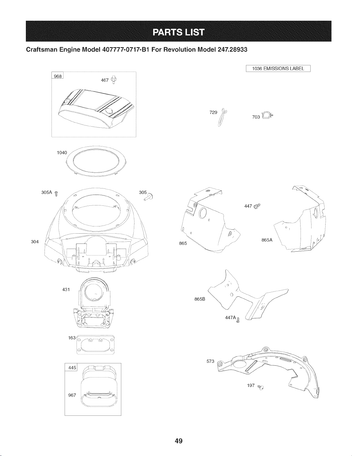
Craftsman Engine IViodel 407777=0717-B1 For Revolution IViodel 247.28933
467 _.>'
U
1036 EMISSIONS LABEL
729 _,d 4_
703 k_.:::,J___
304
305A
_- .............. -. -.
431
i
I
865B
0
447A_
447 (_
/
/
/
/
865A ',,
967
573
49
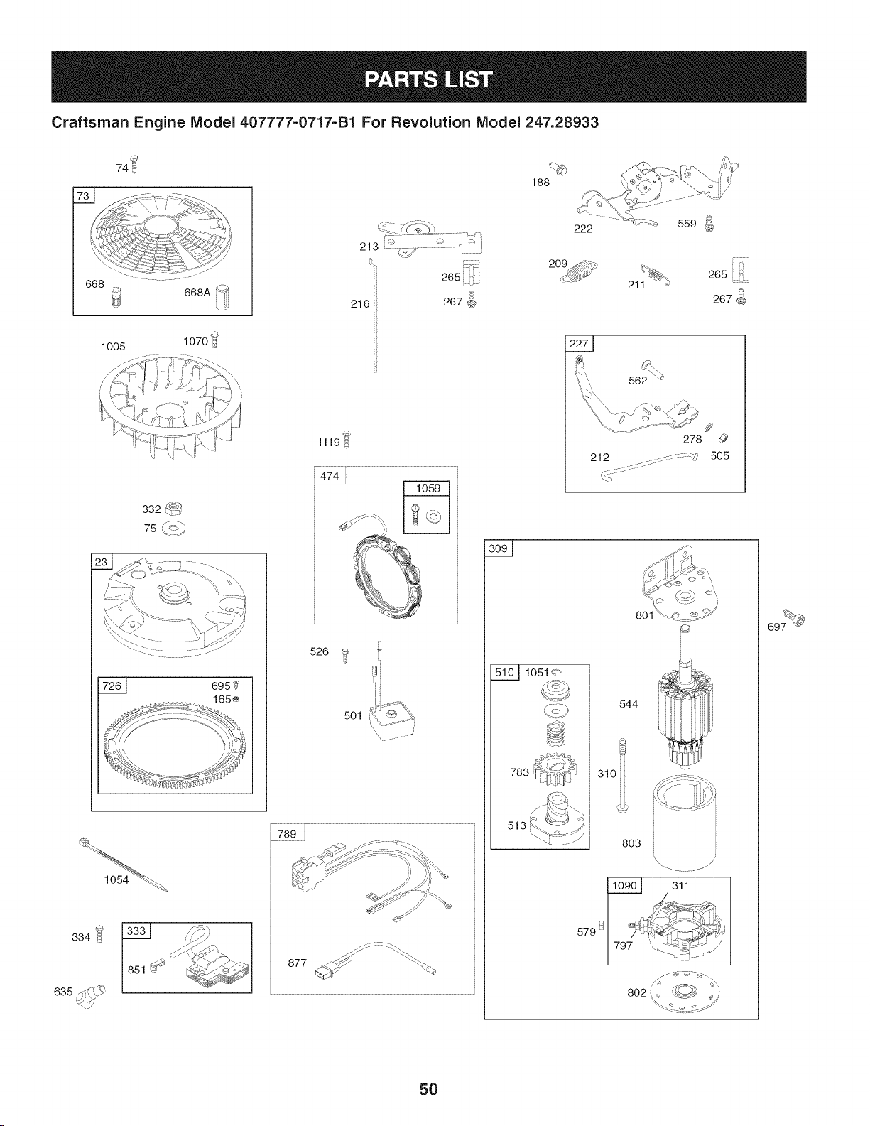
Craftsman Engine IViodel 407777-0717-B1 For Revolution IViodel 247.28933
@
74
188
668
1005
332 _<-_P_
)
213 _.#,j
265
J
216 267
H
1119U
474
526
5Ol_ _.._
789
877 >_' "_._
222 559 ]oJ
@
265 ii_i
267_
562 _
278
212 ......::s- : : :q
::::::::::::::::::::
5O5
801
_1051<"
783
513
544
310
803
311
579 !_
5O

Craftsman Engine IViodel 407777=0717=B1 For Revolution IViodel 247.28933
795118 CylinderAssembly
2 499585 Kit-Bushing/Seal(MagnetoSide)
3. 391086s Seal-Oil(MagnetoSide)
4 796230 Sump-Engine
5 796231 Head-Cylinder(Cylinder#1)
5A 796232 Head-Cylinder(Cylinder#2)
7.+ 693997 Gasket-CylinderHead
8 792185 BreatherAssembly
9 690937 Gasket-Breather
10 697551 Screw(BreatherAssembly)
11 792184 Tube-Breather
12. 697227 Gasket-Crankcase
13 793988 Screw(CylinderHead)
15 690946 Plug-OilDrain
16 796540 Crankshaft
20, 795387 Seal-Oil(PTOSide)
22 694966 Screw(CrankcaseCover/Sump)
23
691053 Flywheel
24 222698s Key-Flywheel
25 793647 PistonAssembly(Standard)
793648 PistonAssembly(.020"Oversize)
26 791787 RingSet(Standard)
791792 RingSet(.020"Oversize)
27 690975 Lock-PistonPin
28 696581 Pin-Piston
29 796209 Rod-Connecting
32 690976 Screw(ConnectingRod)
33 697576 Valve-Exhaust
34 792200 Valve-Intake
35 694865 Spring-Valve(Intake)
36 694865 Spring-Valve(Exhaust)
40 690964 Retainer-Valve
42 499586 Keeper-Valve
45 690977 Tappet-Valve
46 792555 Camshaft
48 698172 Short Block
50 695241 Manifold-Intake
510.+ 795123 Gasket-intake
D = O 0
690950 Gasket-intake
53 690951 Stud(Carburetor)
54 699816 Screw(IntakeManifold)
73 494439 Screen-Rotating
74 698425 Screw(RotatingScreen)
75 691056 Washer(Flywheel)
95 690718 Screw(ThrottleValve)
98 0 699721 Kit-IdleSpeed
1040 694918 Pin-FloatHinge
1050 698537 Valve-FloatNeedle
108 699723 Valve-Choke
117 792296 Jet-Main(Standard)(LeftJet)
117A 842627 Jet-Main(Standard)(RightJet)
118 699457 Jet-Main(HighAltitude)(Left Jet)
118A 699733 Jet-Main(HighAltitude)(RightJet)
121 792455 Kit-CarburetorOverhaul
125 792295 Carburetor
130 690993 Valve-Throttle
131 499805 Kit-ThrottleShaft
133 699724 Float-Carburetor
135 699729 Tube-FuelTransfer
1370 690994 Gasket-FloatBowl
141 699722 Kit-ChokeShaft
142 699726 Nozzle-Carburetor
146 690979 Key-Timing
150 690995 Gasket-Nozzle
163 691001 Gasket-AirCleaner
165 693148 Nut (RingGear)
187 791766 Line-Fuel(CutTo RequiredLength)
188 697551 Screw(ControlBracket)
192 690083 Adjuster-RockerArm
197 697820 Screw(Back Plate)
209 796224 Spring-Governor(Yellow/Black)
211 691019 Spring-GovernedIdle(Orange)
212 695238 Link-Throttle
213 691021 Bracket-ChokeControl
216 691022 Link-Choke
219 793338 Gear-Governor
• Includedin EngineGasketSet, KeyNumber358.
0 Includedin CarburetorOverhaulKit,KeyNumber121.
+ IncludedinValveGasketSet, KeyNumber1095.
51

Craftsman Engine IViodel 407777=0717=B1 For Revolution IViodel 247.28933
690412 Washer(GovernorGear)
221 841026 Cup-Governor
222 796630 Bracket-Control
227 796223 Lever-GovernorControl
231 690718 Screw(ChokeValve)
239 792028 Switch-OilPressure
240 695666 Filter-Fuel
250 690957 Retainer-Breather
252 794389 Collector-Oil
265 691024 Clamp-Casing
267 695314 Screw(CasingClamp)
276 695410 Washer-Sealing
278 792651 Washer(GovernorControlLever)
287 697551 Screw(DipstickTube)
304 796678 Housing-Blower
305 691005 Screw(BlowerHousing)
305A 790690 Screw(BlowerHousingto IntakeElbow)
306 794953 Shield-Cylinder
309 497595 Motor-Starter
310 690323 Screw(Starter Motor)
311 497608 BrushSet
332 691059 Nut(Flywheel)
333 691060 Armature-Magneto
334 691061 Screw(MagnetoArmature)
337 491055s Plug-Spark
358 694012 GasketSet-Engine
385 697551 Screw(Fuel Pump)
387 808656 Pump-Fuel
404 690442 Washer(GovernorCrank)
415 690283 Plug(CrankcaseCover/Sump)
418 690999 Plate-Carburetor
431 792297 Elbow-Intake
445 792105 Filter-AirCleanerCartridge
447 691003 Screw(Air GuideCover)(Short)
447A 697551 Screw(Air GuideCover)(Long)
467 790697 Knob-AirCleaner
474 696457 Alternator
_= " O O
691188 Regulator
505 691029 Nut(GovernorControlLever)
510 696541 Drive-Starter
513 692024 Clutch-Drive
523 1691036 J D!pst!ck
524 691032
525 691037
526 691129
544 692034
552 690552
552A 690553
559 695314
562 690311
573
579
601
Seal-DipstickTube
Tube-Dipstick
•Screw(Regulator)
Armature-Starter
Bushing-GovernorCrank
Bushing-GovernorCrank
Screw(RemoteChoke)
Bolt (GovernorControlLever)
790444 Plate-Back
691029 Nut(StarterCable)
691038 Hose-Clamp(Black)
601A 791850 Hose-Clamp(Green)
615 698290 Retainer-GovernorShaft
616 691045 Crank-Governor
617 697891 SeaI-ORing(intake Manifold)(Red)
628 697551 Screw(FuelPumpBracket)
633 690998 Seal-Choke/ThrottleShaft
635 66538s Boot-SparkPlug
654 690958 Nut(Carburetor)
668 691500 Spacer(RotatingScreen)
668A 691215 Spacer(RotatingScreen)
672 690234 Gasket-CarburetorPlate
691 790574 Seal-GovernorShaft
695 693149 Screw(RingGear)
697 690372 Screw(DriveCap)
703 691010 Clip
718 690959 Pin-Locating(Cylinder)
726 499612 Gear-Ring
729 694123 Clip-Wire
741 690980 Gear-Timing
742 690328 Retainer-ERing
750 796208 Screw(Oil PumpCover)
• includedin EngineGasketSet, KeyNumber358.
O IncludedinCarburetorOverhaulKit, KeyNumber121.
+ IncludedinValveGasketSet, KeyNumber1095.
52

Craftsman Engine IViodel 407777=0717=B1 For Revolution IViodel 247.28933
D = O
695708 Gear-Pinion
788 793145 Bracket-FuelPump
789 698330 Harness-Wiring
797 693167 Nut (BrushRetainer)
798 697890 Screw(RockerArm)
801 691283 Cap-Drive
802 691286 Cap-End
803 Housing-Starter(Servicedby497595
StarterMotorOnly,Reference309)
842 691031 Seal-O Ring(DipstickTube)
847 499602 Dipstick/TubeAssembly
850 100106 Sealant-Liquid(LiquidSealantis inter
changeablewith the RockerCover
Gasketand BreatherGasket)
851 493880s Terminal-SparkPlug
865 691012 Cover-AirGuide(Cylinder#1)
865A 796541 Cover-AirGuide(Cylinder#2)
865B 792286 Cover-AirGuide(Valley)
868o+ 690968 Seal-Valve
877 790544 Wire/Connector-Alternator
883° 690970 Gasket-Exhaust
914 691127 Screw (RockerCover)
918 793147 Hose-Vacuum
929 695239 Screw (ChokeControlBracket)
943 796222 Seal-O Ring(Oil PumpCover)
947 841546 Solenoid-Fuel
965 796221 Cover-OilPump
967 792303 Filter-PreCleaner
968 795120 Cover-AirCleaner
975 793592 Bowl-Float
987 691000 Seal-ThrottleShaft
_= O O
791236 Fan-Flywheel
1013 690954 Nipple-OilFilter
1017 796214 Screen-OilPump
1022.+ 690971 Gasket-RockerCover
1023 793146 Cover-Rocker(Cylinder#1)
1023A 499600 Cover-Rocker(Cylinder#2)
1024 796220 Pump-Oil
1026 690981 Rod-Push(Steel)
690982 Rod-Push(Aluminum)
1027 795890 Filter-Oil
1029 690972 Arm-Rocker
1036 Label-Emissions(Availablefrom a Briggs
& StrattonAuthorizedDealer)
1040 791237 Plate-Trim
1051 691265 Ring-Retaining(StarterMotor)
1054 280275 Tie-Cable
1058 277103 Operator'sManual
1059 698516 Kit-Screw/Washer(Alternator)
1070 791680 Screw(FlywheelFan)
1090 691293 Retainer-Brush
1095 694013 GasketSet-Valve
1100 791959 Pivot-RockerArm
1119 691183 Screw(Alternator)
1123 841653 Seal-ORing(SolenoidRetainer)
1124 690988 Seal-ORing(FuelTransferTube)
1126 690991 Screw(FuelTransferTube)
1127 695407 Screw(Float Bowl)
1128 690990 Screw(CarburetorNozzle)
1169 690990 Screw(CarburetorCoverPlate)
1329 44L7770037 ReplacementEngine
1330 273521 RepairManual
IncludedinEngineGasketSet, KeyNumber358.
0 Includedin CarburetorOverhaulKit,KeyNumber121.
+ IncludedinValveGasketSet, KeyNumber1095.
53

MTD CONSUMER GROUP INC (MTD), the California Air Resources Board (CARB)
and the United States Environment Protection Agency (U. S. EPA)
Emission Control System Warranty Statement
(Owner's Defect Warranty Rights and Obligations)
EMISSIONCONTROLSYSTEMCOVERAGEIS APPLICABLETOCERTIFIEDENGINESPURCHASEDIN CALIFORNIAIN 2005 ANDTHERE-
AFTER,WHICHARE USEDIN CALIFORNIA,ANDTO CERTIFIEDMODELYEAR2005AND LATERENGINESWHICHARE PURCHASEDAND
USEDELSEWHEREIN THE UNITEDSTATES.
Californiaandelsewherein the UnitedStatesEmissionControlDefectsWarrantyCoverage
The CaliforniaAir ResourcesBoard(CARB),U.S. EPAandMTDarepleasedto explaintheemissionscontrol systemwarrantyon your modelyear
2006and latersmalloff-roadengine.In California,new smalloff-roadenginesmustbe designed,builtand equippedto meet theStatesanti-smog
standards.Elsewhereinthe UnitedStates,newnon-road,spark-ignitionenginescertifiedfor model2005and later,mustmeet similarstandardsset
forthby the U. S. EPA.MTDmustwarrantythe emissioncontrolsystemonyourenginefor the periodof timelistedbelow,providedtherehasbeen
noabuse,neglector impropermaintenanceof your smalloff-roadengine.
Youremissioncontrolsystemmayincludepartssuch as the carburetor,fuel-injectionsystem,the ignitionsystem,and catalyticconverter,fuel
tanks,fuel lines,fuel caps,valves,canisters,filters,vaporhoses,clamps,connectors,andotherassociatedemission-relatedcomponents.
Wherea warrantableconditionexists,MTDwill repairyoursmall off-roadengineat no cost to yourincludingdiagnosis,partsand labor.
MANUFACTURER'S WARRANTY COVERAGE:
Thisemissionscontrolsystemis warrantedfor twoyears.If anyemission-relatedpart onyourengineis defective,the part will berepairedor
replacedby MTD.
OWNER'S WARRANTY RESPONSIBILITIES:
As the smalloff-roadengineowner,youare responsibleforthe performanceof the requiredmaintenancelistedinyour Owner'sManual.MTD
recommendsthatyou retainall yourreceiptscoveringmaintenanceson yoursmall off-roadengine,but MTDcan not denywarrantysolelyfor the
lackof receiptsor for yourfailureto ensurethe performanceto allscheduledmaintenance.
As the smalloff-roadengineowner,youshouldhoweverbe awarethat MTDmaydenyyour warrantycoverageif yoursmall off-roadengine or part
hasfaileddue toabuse, neglect,impropermaintenanceor unapprovedmodifications.
Youare responsiblefor presentingyour smalloff-roadengineto an AuthorizedMTDServiceDealeras soonas a problemexists.Thewarranted
repairsshouldbe completedin a reasonableamountof time,notto exceed30 days.
If youhaveanyquestionsregardingyourwarrantyrightsand responsibilities,you shouldcontacta MTDService Representativeat 1-800-800-7310
andaddressis MTDCONSUMERGROUP,RO. Box361131,ClevelandOH,44136-0019.
DEFECTS WARRANTY REQUIREMENTS FOR 1995 AND LATER SMALL OFF-ROAD ENGINES:
Thissectionappliesto 1995andlater smalloff-roadengines.The warrantyperiodbeginson the datethe engineor equipmentis deliveredto an
ultimatepurchaser.
(a) GeneralEmissionsWarrantyCoverage
MTDmustwarrantto the ultimatepurchaserandeachsubsequentpurchaserthat the engineis:
(1)Designed,built,andequippedsoas to conformwith all applicableregulationsadoptedby the Air ResourcesBoardpursuantto itsauthorityin
Chapters1 and 2,Part5, Division26of the Healthand SafetyCode;and
(2) Freefrom defectsin materialsandworkmanshipthatcausethe failureof a warrantedpart to be identicalin all materialrespectsto the partas
describedin theenginemanufacturer'sapplicationfor certificationfora periodof twoyears.
(b)The warrantyonemissions-relatedpartswill be interpretedas follows:
(1)Anywarrantedpart that is not scheduledfor replacementas requiredmaintenancein the writteninstructionsrequiredby Subsection(c)
mustbe warrantedfor the warrantyperioddefinedinSubsection(a)(2). If any such partfails duringthe periodof warrantycoverage,it mustbe
repairedor replacedby MTDaccordingto Subsection(4)below.Anysuch part repairedor replacedunderthewarrantymustbe warrantedfor
the remainingwarrantyperiod.
(2)Any warrantedpartthat is scheduledonlyfor regularinspectioninthe writteninstructionsrequiredby Subsection(c) mustbe warrantedfor
thewarrantyperioddefinedin Subsection(a)(2).A statementin such writteninstructionsto the effectof"repairor replaceas necessary"will
not reducethe periodof warrantycoverage.Anysuch part repairedor replacedunderwarrantymustbe warrantedforthe remainingwarranty
period.
(3) Anywarrantedpartthat whichis scheduledfor replacementas requiredmaintenancein the writteninstructionsrequiredby Subsection(c)
mustbe warrantedfor the periodof time prior to the first scheduledreplacementpointforthat part. If the part fails prior to thefirst scheduled
replacement,the part mustbe repairedor replacedby MTDaccordingto Subsection(4) below.Any suchpart repairedor replacedunder
warrantymustbe warrantedfor the remainderof the periodpriorto the first scheduledreplacementpointfor the part.
(4)Repairorreplacementofanywarrantedpartunderthewarrantyprovisionsofthisarticlemustbeperformedatnochargetotheownerata
warrantystation.
(5)NotwithstandingtheprovisionsofSubsection(4)above,warrantyservicesorrepairsmustbeprovidedatallMTDdistributioncentersthat
arefranchisedtoservicethesubjectengines.
(6)Theownermustnotbechargedfordiagnosticlaborthatleadstothedeterminationthatawarrantedpartisinfactdefective,providedthat
suchdiagnosticworkisperformedatawarrantystation.
(7)Theenginemanufacturerisliablefordamagestootherenginecomponentsproximatelycausedbyafailureunderwarrantyofanywarranted
part.
(8)Throughouttheengine'swarrantyperioddefinedinSubsection(a)(2),MTDwillmaintainasupplyofwarrantedpartssufficienttomeetthe
expecteddemandforsuchparts.
(9)Anyreplacementpartmaybeusedintheperformanceofanywarrantymaintenanceorrepairsandmustbeprovidedwithoutchargetothe
owner.SuchusewillnotreducethewarrantyobligationsofMTD.
(10)Add-onormodifiedpartsthatarenotexemptedbytheAirResourcesBoardmaynotbeused.Theuseofanynon-exemptedadd-onor
modifiedpartsshallbegroundsfordisallowingawarrantyclaimmadeinaccordancewiththisarticle.Theenginemanufacturershallnotbe
liableunderthisarticletowarrantfailuresofwarrantedpartscausedbytheuseofnon-exemptedadd-onormodifiedpart.
(c) MTDwill includea copy of the followingemissionwarrantyparts list with each newengine,usingthoseportionsof the list applicableto the
e__&gine.
(1)FuelMeteringSystem
• Coldstart enrichmentsystem(soft choke)
,,Carburetorandinternalparts
• Fuel Pump
• FuelTank
(2)Air InductionSystem
• Aircleaner
• Intakemanifold
(3) IgnitionSystem
• Sparkplug(s)
• MagnetoIgnitionSystem
(4)ExhaustSystem
Catalyticconverter
• SAI (Reedvalve)
(5) MiscellaneousItemsUsedin AboveSystem
Vacuum,temperature, position,timesensitivevalvesand switches
Connectorsandassemblies
(6) Evaporativecontrol
• Fuel Hosecertifiedfor ARBevaporativeemissionof 2006.
• Fuel HoseClamps
Tetheredfuel cap
Carboncanister
Vaporlines
GD0C-100174Rev.B
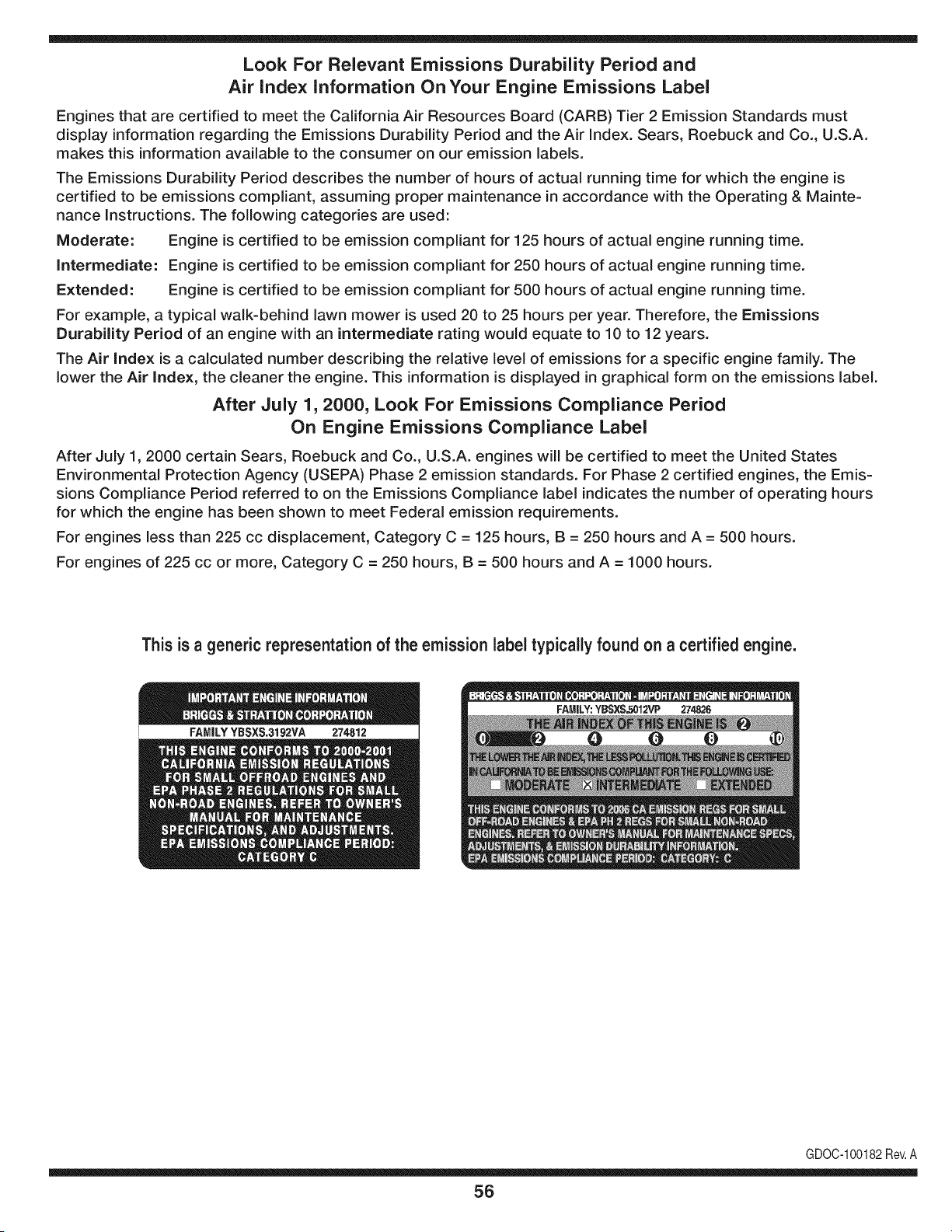
Look For Relevant Emissions Durability Period and
Air index information On Your Engine Emissions Label
Engines that are certified to meet the California Air Resources Board (CARB) Tier 2 Emission Standards must
display information regarding the Emissions Durability Period and the Air Index. Sears, Roebuck and Co., U.S.A.
makes this information available to the consumer on our emission labels.
The Emissions Durability Period describes the number of hours of actual running time for which the engine is
certified to be emissions compliant, assuming proper maintenance in accordance with the Operating & Mainte-
nance Instructions. The following categories are used:
Moderate: Engine is certified to be emission compliant for 125 hours of actual engine running time.
Intermediate: Engine is certified to be emission compliant for 250 hours of actual engine running time.
Extended: Engine is certified to be emission compliant for 500 hours of actual engine running time.
For example, a typical walk-behind lawn mower is used 20 to 25 hours per year. Therefore, the Emissions
Durability Period of an engine with an intermediate rating would equate to 10 to 12 years.
The Air Index is a calculated number describing the relative level of emissions for a specific engine family. The
lower the Air Index, the cleaner the engine. This information is displayed in graphical form on the emissions label.
After July 1,2000, Look For Emissions Compliance Period
On Engine Emissions Compliance Label
After July 1, 2000 certain Sears, Roebuck and Co., U.S.A. engines will be certified to meet the United States
Environmental Protection Agency (USEPA) Phase 2 emission standards. For Phase 2 certified engines, the Emis-
sions Compliance Period referred to on the Emissions Compliance label indicates the number of operating hours
for which the engine has been shown to meet Federal emission requirements.
For engines less than 225 cc displacement, Category C = 125 hours, B = 250 hours and A = 500 hours.
For engines of 225 cc or more, Category C = 250 hours, B = 500 hours and A = 1000 hours.
This is a generic representation of the emission label typically found on a certified engine.
FAMILYYBSXS.3192VA 274812
GDOC-100182Rev.A
56
Congratulationson makinga smart purchase.YournewCraftsman®
productis designedand manufacturedfor yearsof dependableopera-
tion.But likeall products,it mayrequirerepairfromtime to time.That's
whenhavinga RepairProtectionAgreementcan saveyoumoneyand
aggravation.
Here'swhatthe RepairProtectionAgreement*includes:
* Expert service byour 10,000professionalrepairspecialists
* Unlimited service and no charge for partsand laboronall
coveredrepairs
* Product replacement upto $1500ifyourcoveredproductcan't be
fixed
* Discountof 10%from regularpriceof serviceand relatedinstalled
partsnotcoveredby theagreement;also,10%off regularpriceof
preventivemaintenancecheck
* Fast help by phone- we call itRapidResolution- phone support
froma Searsrepresentative.Thinkof usas a "talkingowner's
manual."
Once youpurchasethe Agreement,a simplephonecall isall thatit
takesfor youto scheduleservice.Youcan call anytimedayor night,or
schedulea serviceappointmentonline.
The RepairProtectionAgreementisa risk-freepurchase.If you cancel
for any reasonduringthe productwarrantyperiod,wewill providea full
refund.Or,a proratedrefundanytimeafter the productwarrantyperiod
expires.Purchaseyour RepairProtectionAgreementtoday!
Some limitations and exclusionsapply. For prices and additional
informationin the U.S.A. call 1-800-827-8855.
*Coverage inCanadavaries on some items.For full details call
Sears Canada at 1-800-381-8665.
Sears Installation Service
ForSearsprofessionalinstallationof homeappliances,garagedoor
openers,waterheaters,and othermajorhomeitems,in the U.S.A.or
Canadacall 1-800-4-MY-HOME®.
57
Declaraci6n de garantia ............................ Pagina 58
Practicas operaci6n seguras ..................... Pagina 59
Montaje ...................................................... Pagina 65
Piezas de repuesto estandar y archivos adjuntos ..
................................................................... Pagina 10
Operaci6n .................................................. Pagina 66
Servicio y Mantenimiento .......................... Pagina 74
Almacenamiento fuera de temporada ....... Pagina 87
Soluci6n de problemas .............................. Pagina 88
Acuerdo de protecci6n para reparaciones .... Pagina 93
Etiquetas de seguridad .............................. Pagina 9
Lista de piezas ........................................... Pagina 32
NOmero de servicio ................................... Cubierta
Posterior
Craftsman de Garantia integro
Cuandose operadoy rnantienendeacuerdocontodaslas instruccionessurninistradas,si no fungiblescualquierpartede esteequipo de
equitaci6nfalladebidoa undefectode materialo rnanodeobra dentrode dos a_osa partirde la fechao la cornpra,Ilarne1-800-659-5917para
organizarde forrnagratuitaen lacasade reparaci6n.
El marcoy el ejedelanteroser_reparadosin cargopor un periodode cinco a_osa partirde la fechade cornpraen casodedefectosde material
o rnanodeobra.
TodoIo anteriorla coberturade la garanfiase aplicaa s61o90 diasa parfir de la fechade cornprasi el equipoestAsiemprea caballoufilizado
paraprop6sitoscornercialeso de alquiler.
Entodos loscasos, si la reparaci6nresultairnposible,elequipode equitaci6nserAsustituidodeforrnagratuitacon el rnisrnornodeloo uno
equivalente.
La bateriase sustituyedeforrnagratuitadurante90 dias a partirde lafechade cornpraencasode defectosde materialo rnanode obra
(nuestraspruebasdernuestranqueno va a celebrarun cargo).
Esta garantia cubre_nicamente defectos de material y mano de obra.Sears no pagar_pot:
• FungiNesquese gastadoduranteel usonormal,incluyendoperonolirnitadoalas hojas,bujias,lirnpiezadeair& correas,filtrosy aceite.
• Norrnade serviciosde rnantenirniento,carnbiosde aceite,o sintonice-ups.
• Tire lasustituci6no reparaci6ndepinchazoscausadosporobjetosdesdeel exterior,comoporejemploclavos,espinas,los tocones,o de
vidrio.
• Carnbiode neurn&ticoso ruedasde sustituci6no reparaci6ncornoconsecuenciade desgastenormal,accidentes,o rnalfuncionarnientoo
rnantenirniento.
• Reparacionesquesean necesariasacausade los abusosdel operador,incluyendoperono lirnitadoa losdaSoscausadospor rernolcar
objetosrn&sall&de la capacidadde rnontarel equipo,afectana losobjetosque doblar el marcoo el cig(Je_al,oel excesode velocidaddel
motor.
• Reparacionesquesean necesariasacausade la negligenciadel operador,incluyendoperono lirnitadoa, el_ctricosy rnec&nicosde los
da_oscausadospor elalrnacenarnientoinadecuado,faltade utilizaci6nde la categoriaapropiaday la cantidadde aceite demotor,el
fracasopara rnantenerla cubiertaclarade losdesechosinflarnables,o el fracasopararnantenerla equitaci6nequipode acuerdoalas
instruccionesque figuranen elmanualdeloperador.
• Motor(sisternadecombustible),la lirnpiezao reparacionescausadasporcombustibledeterrninadopuedanestarcontarninadoso oxidado
(rancio).Engeneral,el combustibledebeserutilizadodentrode los 30dias siguientesa su fechadecornpra.
• Normaldesgastey deteriorode los acabadosexteriores,o la etiquetadel productode reernplazo.
Estagaranfias61otendrAvalidezrnientrasel productose utiliceen los EstadosUnidos.
Estagaranfiale otorgaderechoslegalesespedficos,pero ustedpodriagozarde otrosderechosen raz6nde su lugarde residencia.
Sears, Roebuck and Co., Hoffman Estates, IL 60179
Aceitedel motor: SAE30
Combustible: Gasolinasin plorno
Bujia: Champion®RC12YC
Motor: Briggs& StrattonPlatinoV-Twin
NSmerode modelo ..........................................................
N_merode serie ..............................................................
Fechade compra .............................................................
Registrearriba el nQrnerodel rnodelo,elnQrnerode seriey lafecha
decornpra
© Sears Brands,LLC 58
Lapresenciade este sirnboloindicaque setrata de instrucciones
irnportantesde seguridadquese deben respetarpara evitar
poneren peligrosu seguridadpersonaly/o materialy la de otras
personas.Lea y siga todaslas instruccionesdeeste manualantes
de poneren funcionarnientoesta rn_.quina.Si no respetaestas
instruccionespodria provocarlesionespersonales.Cuandoveaeste
sirnbolo,ipresteatenci6na la advertencia!
PROPOSICION 65 DE CALIFORNIA
Elescapedel motordeeste producto,algunosde suscornponentes
y algunoscornponentesdelvehiculocontieneno liberan sustancias
quirnicasqueel estado de Californiaconsideraque puedenproducir
c_.ncer,defectosde nacirnientouotrosproblernasreproductivos.
Losbornesde la bateriay los accesoriosdines contienenplornoy
cornpuestosde plorno,sustanciasquirnicasque seg_nIo estableci-
do pot el Estadode Californiacausanc_.ncery da_osen el sisterna
reproductivo.Ldveselas manos despu_sde estaren contacto
con estoscomponentes.
Estarn_.quinarueconstruidapara seroperadade acuerdocon
las reglasde seguridadcontenidasen estemanual.AI igualque
concualquiertipo deequipornotorizado,un descuidoo error por
partedel operadorpuedeproducirlesionesgraves.Estarn_.quina
es capazde arnputarrnanosy piesy de arrojarobjetoscon gran
fuerza.Deno respetarlas instruccionesde seguridadsiguientesse
puedenproducirlesionesgraveso larnuerte.
Su responsabilidad--Restrinja el usode esta rn_.quina
rnotorizadaalas personasque lean,cornprendany respetenlas
advertenciase instruccionesque aparecenen estemanualyen la
rn_.quina.
iGI.IARI)E ESTASINSTRUCCIONES!
FUNCIONAIVIIENTO GENERAL
• Lea,entienday curnplatodaslas instruccionesincluidasen
la rn_.quinayen los rnanualesantesde rnontarlay utilizarla.
Guardeestemanualenun lugarseguroparaconsultasfuturasy
peri6dicas,asi cornoparasolicitarrepuestos.
• Farniliaricesecontodoslos controlesy con el usoadecuado
delos rnisrnos.Sepac6rnodetenerla rn_.quinay desactivarlos
controlesr_.pidarnente.
• No perrnitanuncaque los ni_osrnenoresde 14a_osutilicen
estarn_.quina.Los ni_osde 14a_osen adelantedeben leer y
entenderlas instruccionesde operaci6ny norrnasdeseguridad
contenidasen este manual,y en la rn_.quinay debenser
entrenadosy supervisadospor unadulto.
• Nuncaperrnitaquelos adultosoperenestarn_.quinasin recibir
antesla instrucci6napropiada.
• Paraayudaraevitarel contactocon las cuchillaso unalesi6npor
algQnobjetoque sea arrojado,rnantengaa los observadores,a
los ayudantes,ni_osy rnascotasalejadosal rnenos25 metrosde
la rn_.quinarnientrasest,. en funcionarniento.Detengala rn_.quina
si alguienentraen lazona.
• Inspeccionerninuciosarnenteel Areadondeutilizar_,el equipo.
Retiretodaslas piedras,palos,cables,huesos,juguetesy otros
objetosextra_osque podrianser recogidosy arrojadospor la
acci6nde las cuchillas.Losobjetosarrojadospor la rn_.quina
puedenproducirlesionesgraves.
• Planifiqueel patr6ndecortedelc_spedque hade seguirpara
evitarla descargade materialhacialoscarninos,las veredas,los
observadores,etc.Eviteadern_.sdescargarmaterialcontralas
paredesy obstruccionesquepodrianprovocarque el material
descargadorebotecontrael operador.
• Paraprotegerselos ojos utilicesiernpreanteojoso antiparras
deseguridadrnientrasoperalarn_.quinao rnientraslaajusta
o repara.Losobjetosarrojadosque rebotanpuedenproducir
lesionesocularesgraves.
• Utilicezapatosde trabajoresistentes,desuelafuerte,asi corno
pantalonesy carnisasajustados.Las prendassueltaso las
alhajaspuedenquedaratrapadasen las piezasrnovibles.Nunca
operela rn_.quinadescalzoo con sandalias.
• Est_atentoa lacortadoray a la direcci6nde la descargade
losaditarnentosy noapuntea nadie.Nuncaoperelacortadora
de c_spedsin queest_nen su lugarapropiadolacubiertade
descargao elcolectorde recortesde cesped.
• Noponga lasrnanoso lospies cercade las piezasrotatoriaso
debajode la plataforrnadecorte. Elcontactocon las cuchillas
puedeproducirla arnputaci6nde rnanosy pies.
• Unacubiertade descargafaltanteo da_adapuedeprovocarel
contactocon lacuchillao lesionespot objetosarrojados.
• Detengala(s)cuchilla(s)cuandoatraviesesenderos,sendaso
carninosde gravay cuandonoest_cortandoel cesped.
• Vigileel tr_.nsitovehicularcuandoest_operandocercadeo en
crucesde carninos.Estarn_.quinanodebe utilizarseen lavia
pQblica.
• Noopereestarn_.quinabajolosefectosdelalcoholode drogas.
• Corteel cespedsolarnentecon luzdediao conunabuenaluz
artificial.
• Nuncatransportepasajeros.
• Desenganchela(s)cuchilla(s)antesdecolocarla rnarchaatr_.s.
Retrocedalentarnente.Siernpremirehaciaabajoy haciaatr_.santes
y rnientrasretrocede,paraevitaraccidentes.
• Reduzcala velocidadantesde dar la vuelta.Operelarn_.quina
suavernente.Evitelaoperaci6nerr_.ticay la velocidadexcesiva.
• Desenganchela(s)cuchilla(s),coloqueelfrenode estaciona-
rniento,detengael motory esperehastaquela(s)cuchilla(s)se
detenga(n)por cornpletoantesde retirarelcolectordec_sped,
vaciarlos recortes,destaparelcanal,retirarrestosde cespedo
desechos,o hacercualquierajuste.
59
• Nuncadeje la rn_.quinaen funcionarnientosinvigilancia.Apague
siernprelascuchillas,coloqueelfrenode rnano,detengael motory
retirela Ilaveantesde bajarsedelvehiculo.
• Tengasurnocuidadoalcargaro descargarla rn_.quinaen un
rernolqueocarni6n.Estaunidadno debeconducirseenascensoo
descensode rarnpas,porquepodrialadearsey provocarlesiones
personalesgraves.En las rarnpaslarn_.quinasedebe ernpujar
rnanualrnenteparacargarlao descargarlacorrectarnente.
• Elsilenciadory el motorse calientany puedencausarquernaduras.
Nolos toque.
• Reviseel espaciolibrepot encirnade lacabezaantesde conducir
bajolas rarnasbajasde _.rboles,cables,cerrarnientosde puertas,
etc.en loscualesel operadorpodriaatorarseo serernpujadofuera
dela rn_.quina,Ioque podriaresultaren lesionesgraves.
• Desenganchetodoslosernbraguesde los accesoriosy presione
totalrnenteel pedaldel frenoantesdeintentararrancarel motor.
• Larn_.quinaest,.diseSadaparacortarc_spedresidencialnormal,
conuna alturanomayora 10".Nointentecortarcespeddernasiado
crecido,seco (porej., pastura)ni pilasde hojassecas.Elc_sped
y las hojassecaspuedenentraren contactoconel escapedel
motory/o acurnularseenla plataforrnade la cortadoradecesped,
convirti_ndoseen unpeligrodeincendio
• Utilicesolarnenteaccesoriosy aditarnentosaprobadosparaesta
rn_.quinapot el fabricantedela rnisrna.Lea,cornprenday siga
todaslasinstruccionesproporcionadasconlosaccesorioso
aditarnentosaprobados.Paraobtenerunalistade losaccesorios
aprobadosy losarchivosadjuntos,Ilarne1-800-659-5917.
• Losdatosestadsticosrnuestranquelosoperadoresde 60 aSos
y rnayoresseven involucradosen un altoporcentajede lesiones
relacionadascontractorescorta cesped.Estosoperadoresdeben
evaluarsu capacidadparaoperarel tractorcortac_spedenforrna
suficienternenteseguraparaprotegersea ellosrnisrnosy a los
dern_.scontralesionesgraves.
Si se presentansituacionesqueno est_.nprevistasen este
manualsea cuidadosoy use el sentidocornQn.Contacto1-800-
659-5917parainforrnaci6ny asistencia.
FUNCIONAiVlIENTO EN PENDIENTES
Las pendientesson unfactorirnportanterelacionadoconaccidentes
porderrapey vuelcosque puedenproducirlesionesgravese incluso
la rnuerte.Laoperaci6nen pendientesrequieremayorprecauci6n.
Si nopuederetrocederen la pendienteo si no se sienteseguro,no
realiceningunaoperaci6ndecorte.
Parasu seguridad,use el indicadorde pendientesque se incluye
cornopartede estemanualpararnedirla pendienteantesde operarla
rn_.quinaen una zonainclinada.Sila pendientees mayorde 15 grados
segQnel rnedidor,no opereesta rn_.quinaenese sector,puespodria
causarlesionesgraves.
HagaIo siguiente:
• Podehaciaarribay abajodelas pendientes,nodeforrnatrans-
versal.Tengacuidadocuandocarnbiede direcci6nal operaren
pendiente.
• Est_atentoa loshoyos,surcos,baches,rocas,uotrosobjetos
ocultos.Elterrenodesniveladopuedevoltearla rn_.quina.Elcesped
altopuedeocultarobst_.culos.
Vayaa bajavelocidad.ElijaunavelocidadIosuficienternentebaja,
de rnodoquenotengaquedetenerseohacercarnbiosrnientras
est,.sobrela pendiente.Losneurn_.ticospodrianperdertracci6n
sobrelaspendientesaQncuandolosfrenosfuncionaranapro-
piadarnente.Siernprernantengala rn_.quinaen carnbiornientras
desciendelaspendientes,parapoderfrenarconel motor.
• Sigalas recornendacionesdel fabricanteparalos pesoso contra-
pesosdelas ruedas,pararnejorarla estabilidadde la rn_.quina.
Pararecornendaciones,Ilarneal 1-800-659-5917.
• Tengaespecialcuidadocon loscolectoresde cespedu otros
aditarnentos.Losrnisrnospuedenrnodificarla estabilidadde la
rn_.quina.
• Hagaquetodoslos rnovirnientosen laspendientesseanlentosy
graduales.Nocarnbierepentinarnentelavelocidadni la direcci6n.
Unfrenadoo carnbiode velocidadrepentinospuedencausarque
el frentede larn_.quinase levantey d_unavolteretahaciaatr_.s,Io
quepodriaproducirlesionesgraves.
• Evitearrancaro detenerseen una pendiente.Si losneurn_.ticos
pierdenlatracci6n,desenganchelascuchillasy descienda
lentarnentela pendiente.
No hagaIo siguiente:
• Nogire sobrelas pendientesarnenosqueseanecesario.Sies
posible,girelentarnentey gradualrnenteduranteel descenso.
• Nocorteel c_spedcercade pozos,hundirnientosoterraplenes.La
cortadoradec_spedpuedevolcarserepentinarnentesiunade las
ruedasest,.sobreelhordede unacantilado,zanjao siun hordese
desrnorona.
• Nointenteestabilizarlarn_.quinaponiendoel pie enel suelo.
• Noutiliceuncolectordecespeden pendientesernpinadas.
• Nopodeel cespedh_rnedo.Unarnenortracci6npodriacausar
derrapes.
• Noparadescender.Elexcesode velocidadpuedehacerqueel
operadorpierdaelcontroldela rn_.quina,ocasionandolesiones
graveseinclusola rnuerte.
• Norernolquecargaspesadasdetr_.sdelosaditarnentos(carritode
basuracargado,podadorade rodillos,etc)en pendientesrnayores
de5 grados.Cuandosedesplazapendienteabajo,el pesoadicional
tiendea ernpujarel tractory puedehacerquese pierdaelcontrol
delrnisrno(porejernplo,el tractorsepuedeacelerar,se reducela
capacidadparafrenary rnaniobrar,losaccesoriospuedenplegarse
cornoun cortaplurnasy hacerqueel tractorvuelque).
NINOS
Puedenocurriraccidentestr_.gicossi el operadornoest,. atentoa la
presenciade niSos.PotIo general,los niSosse sientenatraidospor
estetipo de rn_.quinasy su funcionarniento.Noentiendenlos riesgos
ni los peligros.Nuncaasurnaque los niSosperrnanecer_.nen el rnisrno
lugardonde losvio pot Qltirnavez.
• Mantengaa losniSosfueradel_.reade trabajoy bajoestricta
vigilanciadeunadultoresponsableadern_.sdelpropiooperador.
Est_alertay apaguela rn_.quinasiun niSoingresaal_.rea.
• Antesy rnientrasest,. retrocediendo,mirehaciaatr_.sy cuidequeno
hayaniSos.
NuncatransporteniSos,aQnconla cuchillaapagada.Podriancaerse
y resultarseverarnenteheridoso interferirconlaoperaci6nsegurade
la rn_.quina.
Tengaextrernaprecauci6ncuandoseaproxirnea esquinasciegas,
portales,arbustos,_.rbolesu otrosobjetosquepuedanirnpedirlever
a unniSoquesecruceenel recorridode larn_.quina.
6O
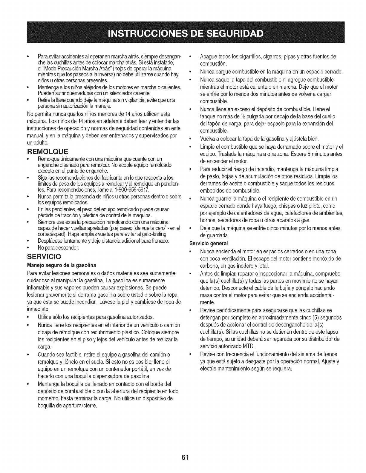
• Paraevitaraccidentesal operaren rnarchaatr_.s,siernpredesengan-
chelascuchillasantesdecolocarrnarchaatr_.s.Siest,. instalado,
el"ModoPrecaucidnMarchaAtr_.s"(hojasdeoperarla rn_.quina,
rnientrasquelospaseosa la inversa)nodebeutilizarsecuandohay
ni_osu otraspersonaspresentes.
• Mantengaa losni_osalejadosde losrnotoresen rnarchao calientes.
Puedensufrirquernadurasconun silenciadorcaliente.
• Retirela Ilavecuandodejela rn_.quinasinvigilancia,evitequeuna
personasinautorizaci6nla rnaneje.
No perrnitanuncaque los ni_osrnenoresde 14a_osutilicenesta
rn_.quina.Losni_osde 14a_osen adelantedeben leer y entenderlas
instruccionesde operaci6ny norrnasde seguridadcontenidaseneste
manual,yen la rn_.quinay deben serentrenadosy supervisadospor
unadulto.
REIVIOLQUE
• Rernolque_nicarnenteconunarn_.quinaquecuenteconun
enganchediseSadopararernolcar.Noacopleequiporernolcado
exceptoen el puntodeenganche.
• SigalasrecornendacionesdelfabricanteenIoque respectaalos
lirnitesdepesode losequiposa rernolcary al rernolqueen pendien-
tes.Pararecornendaciones,Ilarneal 1-800-659-5917.
• Nuncaperrnitala presenciade niSosu otraspersonasdentroosobre
losequiposrernolcados.
• Enlaspendientes,elpesodelequiporernolcadopuedecausar
p_rdidadetraccidny perdidadecontrolde larn_.quina.
• Siernpreuseextralaprecauci6nrernolcandoconunarn_.quina
capazdehacervueltasapretadas(p.ejpaseo"devueltacero"- en el
cortacesped).Hagaarnpliasvueltasparaevitaral gato-knifing.
• Despl_.ceselentarnentey dejedistanciaadicionalparafrenado.
• Noparadescender.
SERVIClO
Manejo seguro de la gasolina
Paraevitarlesionespersonaleso daSosrnaterialessea surnarnente
cuidadosoal rnanipularla gasolina.Lagasolinaes surnarnente
infiarnabley sus vaporespuedencausarexplosiones.Se puede
lesionargravernentesi derrarnagasolinasobreustedo sobrela ropa,
ya que_sta se puedeincendiar. L_.vesela piely c_.rnbiesede ropade
inrnediato.
• Utilices61olos recipientesparagasolinaautorizados.
• NuncaIlenelos recipientesenel interiorde unvehiculoo carnidn
o cajade rernolquecon recubrirnientopl_.stico.Coloquesiernpre
los recipientesen el piso y lejosdel vehiculoantesde realizarla
carga.
• Cuandoseafactible,retireel equipoa gasolinadel carni6no
rernolquey II_neloen elsuelo.Siesto no es posible,Ileneel
equipoen unrernolqueconun contenedorport_.til,envez de
hacerlocon una boquilladispensadoradegasolina.
• Mantengala boquillade Ilenadoencontactoconel hordedel
dep6sitode combustibleocon la aberturadel recipienteen todo
rnornento,hastaterrninarla carga. No utiliceundispositivode
boquilladeapertura/cierre.
• Apaguetodosloscigarrillos,cigarros,pipasy otrasfuentesde
cornbustidn.
• Nuncacarguecombustibleen la rn_.quinaen un espaciocerrado.
• Nuncasaquela tapadel combustibleni agreguecombustible
rnientrasel motorest,.calienteo enrnarcha.Dejequeel motor
seenfrie por Iornenosdos rninutosantesde volvera cargar
combustible.
• NuncaIleneen excesoel dep6sitode combustible.Lleneel
tanqueno rn_.sde 1/2pulgadapor debajode la basedel cuello
del tap6ndecarga,paradejar espaciopara la expansi6ndel
combustible.
• Vuelvaa colocarlatapa dela gasolinay ajQstelabien.
• Lirnpieel combustiblequese hayaderrarnadosobreel motory el
equipo.Trasladela rn_.quinaa otrazona.Espere5 rninutosantes
de encenderel motor.
• Parareducirel riesgode incendio,rnantengala rn_.quinalirnpia
de pasto,hojasy de acurnulacidnde otros residuos.Lirnpielos
derrarnesde aceiteo combustibley saquetodos los residuos
ernbebidosde combustible.
• Nuncaguardela rn_.quinao el recipientedecombustibleen un
espaciocerradodondehayafuego,chispaso luz piloto,corno
porejernplodecalentadoresdeagua,calefactoresde arnbientes,
hornos,secadoresde ropau otrosaparatosa gas.
• Dejeque la rn_.quinase enfriecincorninutospor Iornenosantes
de guardarla.
Servicio general
• Nuncaenciendael motoren espacioscerradosoen unazona
con pocaventilacidn.El escapedel motorcontienernondxidode
carbono,ungas inodoroy letal.
• Antesdelirnpiar,repararo inspeccionarla rn_.quina,cornpruebe
que la(s)cuchilla(s)y todaslas partesenrnovirnientose hayan
detenido.Desconecteel cablede la bujfay p6ngalohaciendo
rnasacontrael motorpara evitarque se enciendaaccidental-
rnente.
• Reviseperi6dicarnenteparaasegurarseque las cuchillasse
detenganpor cornpletoenaproxirnadarnentecinco(5) segundos
despu_sdeaccionarel controlde desenganchede la(s)
cuchilla(s).Si las cuchillasno se detienendentrodeeste lapso
de tiernpo,su unidaddeber_,ser reparadapor su distribuidorde
servicioautorizadoMTD.
• Reviseconfrecuenciaelfuncionarnientodelsisternade frenos
ya queest,. sujetoa desgasteporla operaci6nnormal.Ajuste y
efectQernantenirnientosegQnse requiera.
61
• Reviselos pernosdemontajedela(s) cuchilla(s)y del motora
intervalosfrecuentespara verificarqueest_n bien apretados.
Adem_.s,inspeccionevisualmentela(s) cuchilla(s)en buscade
daSos(por ejemplo,desgasteexcesivo,abolladuras,rajaduras,
etc.). Reemplacela(s)cuchilla(s)Qnicamentecon lascuchillas
defabricantesde equiposoriginales(O.E.M.)listadasen este
manual.Elusode piezasqueno cumplencon las especifi-
cacionesdel equipooriginal podriatenercomoresultadoun
rendimientoincorrectoy adem_.sponeren riesgola seguridad.
• Lascuchillasdelas podadorassonmuy afiladas.Envuelvala
cuchillao utiliceguantesy extremelasprecaucionescuando
efectQemantenimiento.
Mantengatodoslos pernos,tuercasy tornillosbienajustados
paraasegurarsede quela m_.quinase encuentraen condiciones
segurasde operaci6n.
• Nuncaaltereel sistemade enclavamientode seguridadni
otrosmecanismosde seguridad.Controleperi6dicamenteque
funcionencorrectamente.
Despu_sde golpearcon algQnobjetoextraSo,detengael motor,
desconecteelcablede la bujfay conecteel motora masa.
Inspeccioneminuciosamentela m_.quinaparaver si est,. daSada.
Repareel daSoantes de arrancary ufilizarla m_.quina.
Nuncatratede hacerajusteso reparacionesa lam&quina
mientrasel motorest&en marcha.
• Loscomponentesdel colectordec_spedy la cubiertade
descarga,estansujetosa desgastey daSosque podriandejar
expuestaspartesen movimientoo permifirque searrojenobjetos.
Paraprotegersuseguridad,verifiquefrecuentementetodoslos
componentesy reempl_.celosinmediatamentes61ocon piezasde
los fabricantesdel equipooriginal,listadosen estemanual.Eluso
de piezasque nocumplencon las especificacionesdel equipo
originalpodriatenercomo resultadoun rendimientoincorrectoy
adem_.sponeren riesgola seguridad.
• Nocambielaconfiguraci6ndel reguladordel motorni Ioopere
a sobrevelocidad.El reguladordel motorcontrolala velocidad
m_.ximaseguradefuncionamientodel motor.
• Mantengao reemplacelasefiquetasde seguridade instrucciones
segQnseanecesario.
Respetelas normasreferentesa ladisposici6ncorrectay las
reglamentacionessobregasolina,aceite,etc. paraprotegerel
medicambiente.
• SegQnla Comisi6ndeSeguridadde Productospara el Consu-
midorde los EstadosUnidos(CPSC)y la Agenciade Protecci6n
Ambientalde los EstadosUnidos(EPA),esteproductotieneuna
vida Qtilmediade siete(7) aSos,6 270 horasde funcionamiento.
AIfinalizarla vidaOtilmedia,adquierauna m_.quinanuevao haga
inspeccionaranualmente_sta Searspor unou otrodistribuidorde
serviciosparacerciorarsede que todoslos sistemasmec_.nicos
y de seguridadfuncionancorrectamentey no tienenexcesivo
desgaste.Si noIo hace,puedenproducirseaccidentes,lesiones
o muerte.
NO MODIFIQUE EL MOTOR
Paraevitarlesionesgraveso lamuerte,no modifiqueel motorbajo
ningunacircunstancia.Si cambialaconfiguraci6ndel reguladordel
motorel motorpuededescontrolarsey operara velocidadesinsegu-
ras.Nuncacambie la configuraci6ndef_.bricadel reguladordel motor.
AVlSO REFERIDO A EMISIONES
Losmotoresqueest_.ncertificadosy cumplencon las regulaciones
de emisionesfederalesEPAy de CaliforniaparaSORE(Equipos
peque_ostodoterreno)est_.ncertificadosparaoperarcongasolina
comQnsin plomoy puedenincluirlos siguientessistemasde control
de emisiones:Modificaci6nde motor(EM) y catalizadorde tresvias
(TWO)siest_.nequipadosde esa manera.
GUARDACHISPAS
EstamAquinaest,.equipadacon unmotorde combusti6ninternay
nodebe ser utilizadaen o cercade unterrenoagrestecubiertopor
bosque,malezaso hierbaexceptosi el sistemade escapedel motor
est,.equipadocon un amortiguadorde chispasquecumplacon las
leyeslocaleso estatalescorrespondientes,en caso de haberlas.
Si se utilizaunamortiguadorde chispasel operadorIo debemantener
en condicionesde usoadecuadas.Enel Estadode Californialas
medidasanteriormentemencionadassonexigidaspor Icy (Arficulo
4442del C6digode RecursosPOblicosde California).Esposible
queexistanleyessimilaresenotrosestados.Lasleyesfederalesse
aplicanen territoriosfederales.
Puedeconseguirelamortiguadorde chispasparael silenciadora
travesde su distribuidorautorizadode motoreso poni_ndoseen
contactoconel centrode servicioSears.
62
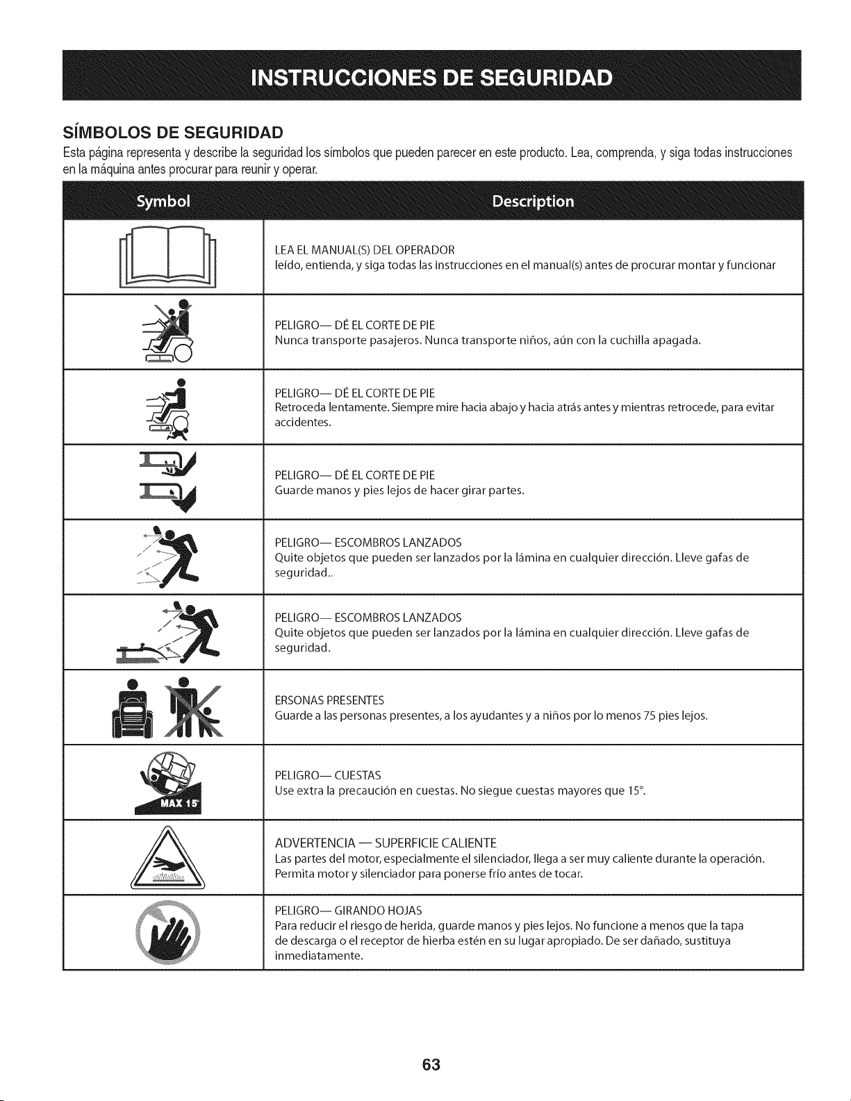
SilVlBOLOS DE SEGURIDAD
Estap&ginarepresentay describela seguridadlos simbolosque puedenpareceren esteproducto.Lea,comprenda,y sigatodas instrucciones
enla m_quinaantesprocurarpara reuniry operar.
0
J
AL
LEA EL MANUAL(S) DEL OPERADOR
leido, entienda, y siga todas las instrucciones en el manual(s) antes de procurar montar y funcionar
PELIGRO-- DE EL CORTE DE PIE
Nunca transporte pasajeros. Nunca transporte ni_os, aun con la cuchilla apagada.
PELIGRO-- DE EL CORTE DE PIE
Retroceda lentamente. Siempre mire hacia abajo y hacia atr_is antes y mientras retrocede, para evitar
accidentes.
PELIGRO-- DE EL CORTE DE PIE
Guarde manos y pies lejos de hacer girar partes.
PELIGRO-- ESCOMBROS LANZADOS
Quite objetos que pueden ser lanzados por la I_imina en cualquier direcci6n. Lleve gafas de
seguridad..
PELIGRO-- ESCOMBROS LANZADOS
Quite objetos que pueden ser lanzados por la I_imina en cualquier direcci6n. Lleve gafas de
seguridad.
ERSONAS PRESENTES
Guarde alas personas presentes, a los ayudantes y a ni_os por Io menos 75 pies lejos.
PELIGRO-- CUESTAS
Use extra la precauci6n en cuestas. No siegue cuestas mayores que 15°.
ADVERTENCIA-- SUPERFICIECALIENTE
Las partes del motor, especialmente el silenciador, Ilega a set muy caliente durante la operaci6n.
Permita motor y silenciador para ponerse frio antes de tocar.
PELIGRO-- GIRANDO HOJAS
Para reducir el riesgo de herida, guarde manos y pies lejos. No funcione a menos que la tapa
de descarga o el receptor de hierba est_n en su lugar apropiado. De ser dahado, sustituya
inmediatamente.
63
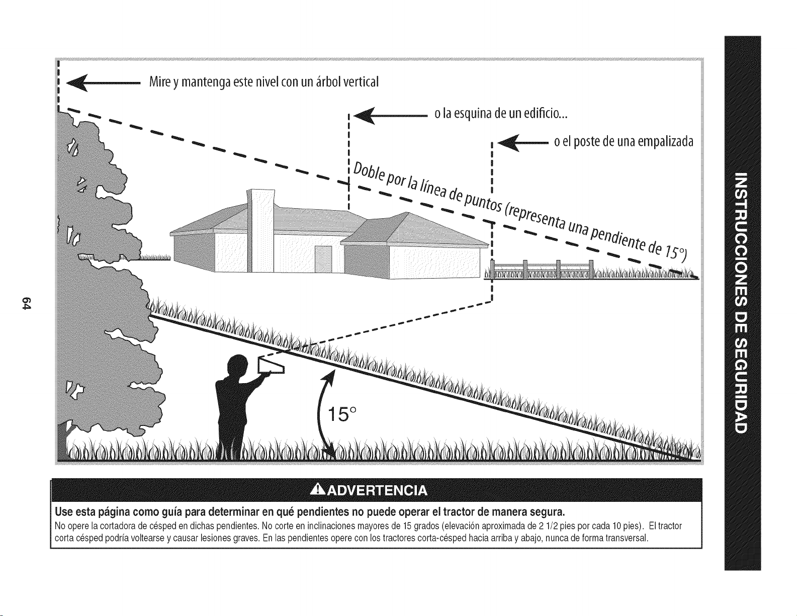
Mireymantenc3aestehive[conun_rbo[vertical
|
...|
15°
Use esta pagina como guia para determinar en qu_ pendientes no puede operar el tractor de manera segura.
No operela cortadorade c_speden dichaspendientes.No corteen inclinacionesmayoresde 15grados(elevaciSnaproximadade 2 1/2pies porcada 10pies). Eltractor
cortac_spedpodrfavoltearsey causarlesionesgraves.Enlas pendientesoperecon lostractorescorta-cespedhaciaarribay abajo,nuncadeformatransversal.
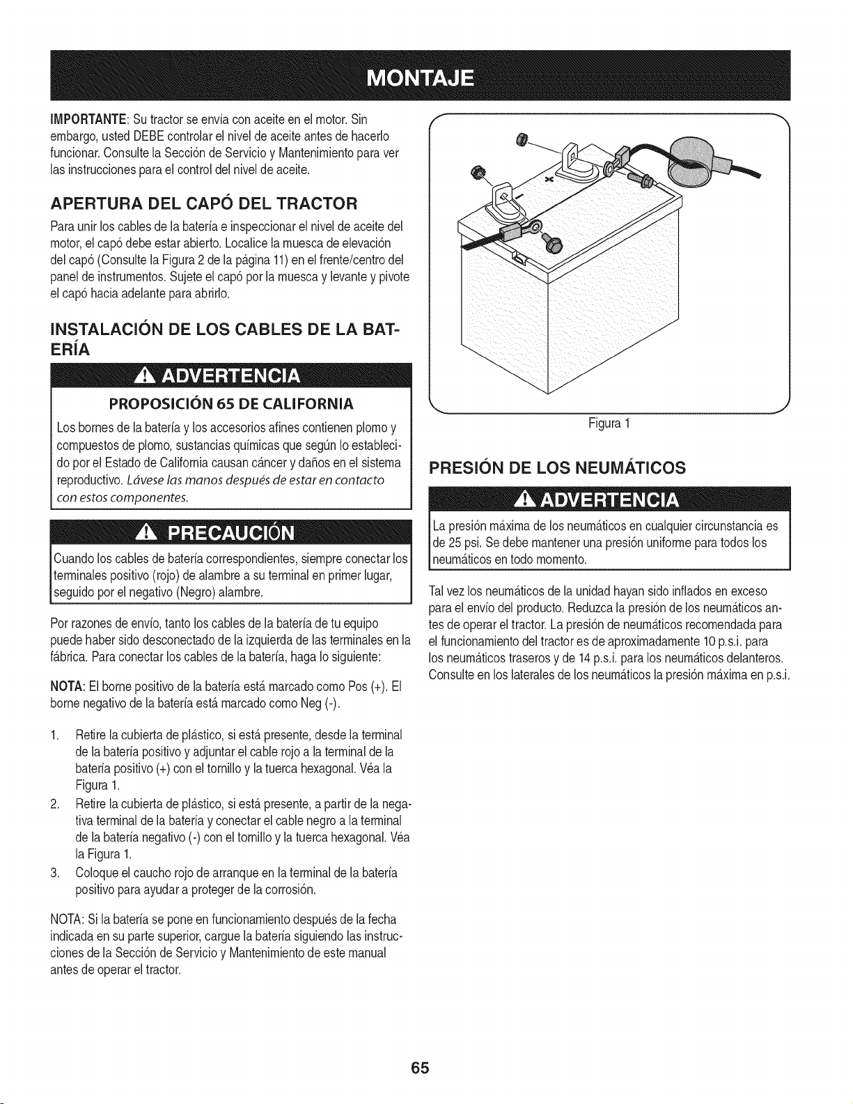
IMPORTANTE:Sutractorseenviaconaceiteenelmotor.Sin
embargo,ustedDEBEcontrolarelniveldeaceiteantesdehacerlo
fundonar.ConsultelaSecci6ndeServMoyMantenirnientoparaver
lasinstrucdonesparaelcontroldelniveldeaceite.
APERTURA DEL CAPO DEL TRACTOR
Paraunir loscablesde la bateriae inspeccionarel nivelde aceite del
motor,el cap6debe estarabierto, Localicela rnuescade elevad6n
delcap6 (ConsultelaFigura2 dela p_.gina11)enel frente/centrodel
panelde instrurnentos.Sujeteel cap6por larnuescay levantey pivote
elcap5 haciaadelanteparaabrNo,
INSTALACIC)N DE LOS CABLES DE LA BAT-
ER{A
PROPOSK:I()N 65 DE CALIFORNIA
Losbornesde la bateriay losaccesoriosafines contienenplornoy
cornpuestosde plorno,sustanciasquirnicasqueseg0nIoestaNeci-
do porel EstadodeCaliforniacausanc_.ncery daSosenel sisterna
reproductivo.Ldveselas manos despu_sde estar en contacto
con estoscomponentes.
f
Figura1
PRESlC)N DE LOS NEUMATICOS
Cuandoloscables de bateriacorrespondientes,siernpreconectarlos
terrninalespositivo(rojo) de alarnbrea su terminalen primerlugar,
segudo pore negatvo (Negro)a arnbre. 1
Porrazonesde envio,tantoloscables de la bateriade tu equipo
puedehabersidodesconectadode la izquierdade lasterrninalesenla
f_.brica.Paraconectarlos cablesde la bateria,hagaIo siguiente:
NOTA:El bornepositivode la bateriaest,. rnarcadocornoPos(+). El
bornenegativode la bateriaest,. rnarcadocornoNeg(-).
LapresiSnmaximade los neurn_.ticosen cualquiercircunstanciaes
de 25psi.Sedebe rnantenerunapresiSnuniforrnepara todos los
neurn_.ticosentodo rnornento.
Talvez los neurn_.ticosde la unidadhayansidoinfiadosen exceso
parael enviodel producto.Reduzcala presiSnde losneurn_.ticosan-
tesde operarel tractor.LapresiSnde neurn_.ticosrecornendadapara
el funcionarnientodel tractores de aproximadarnente10p.s.i,para
los neurn_.ticostraserosy de 14 p.s.i,para los neurn_.ticosdelanteros.
Consulteen los lateralesde losneurn_.ticosla presiSnmaximaen p.s.i.
1. Retirela cubiertadepl_.stico,si est,.presente,desdela terminal
de labater[apositivoy adjuntarel cable rojoa la terminalde la
bateriapositivo(+)con eltornilloy latuercahexagonal.Wa la
Figura1.
2. Retirela cubiertadepl_.stico,si est,.presente,a partirde la nega-
tivaterminalde la bateriay conectarel cablenegroa laterminal
de labaterianegativo(-) con eltornilloy latuercahexagonal.Wa
la Figura1.
3. Coloqueel cauchorojodearranqueen la terminalde la bateria
positivopara ayudara protegerde la corrosiSn.
NOTA:Si la bateriase poneen funcionarnientodespu_sdela fecha
indicadaen su partesuperior,carguela bateriasiguiendolasinstruc-
cionesde la SecciSnde Servicioy Mantenirnientode estemanual
antesde operareltractor.
65
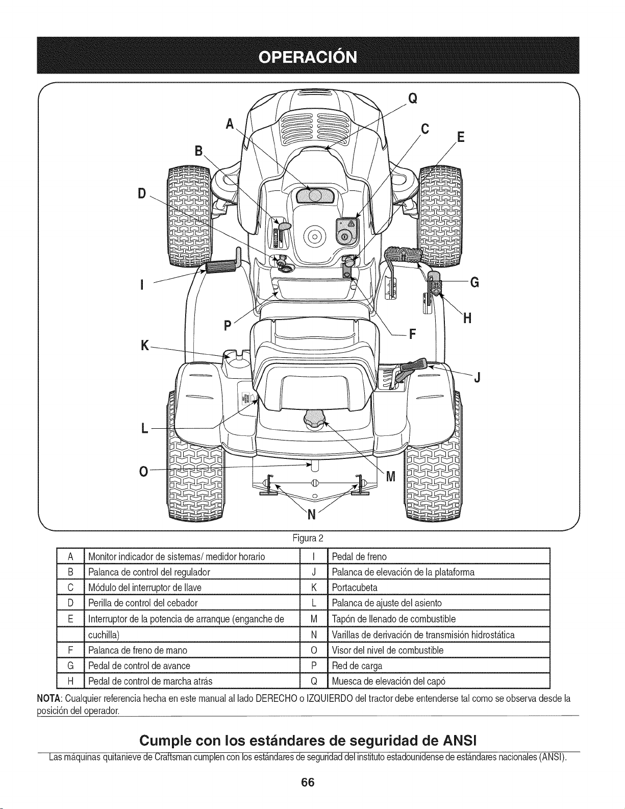
Q
A.. C
E
D
P
L
Figura2
A Monitorindicadorde sistemas/medidorhorario I
B Palancade controldel regulador J
C M6dulodel interruptorde Ilave K
D Perillade controldelcebador L
E Interruptorde la potenciade arranque(enganchede M
cuchilla) N
F Palancade frenode mano 0
G Pedalde controlde avance P
H Pedalde controlde marchaatr_.s Q
Pedaldefreno
Palancade elevaci6nde la plataforma
Portacubeta
Palancade ajustedel asiento
Tap6nde Ilenadode combustible
Varillasde derivaci6nde transmisi6nhidrost_.tica
Visordel nivelde combustible
Redde carga
Muescade elevaci6ndel cap6
NOTA:Cualquierreferenciahechaenestemanualal lado DERECHOo IZQUIERDOdeltractordebe entendersetal como seobservadesdela
posici6ndeloperador.
Cumple con los estandares de seguridad de ANSI
Lasm_,qulnasquitanievedeCraftsmancumplenconlosest_.ndaresdeseguridaddel institutoestadounidensedeest_.ndaresnacionales(ANSI).
66
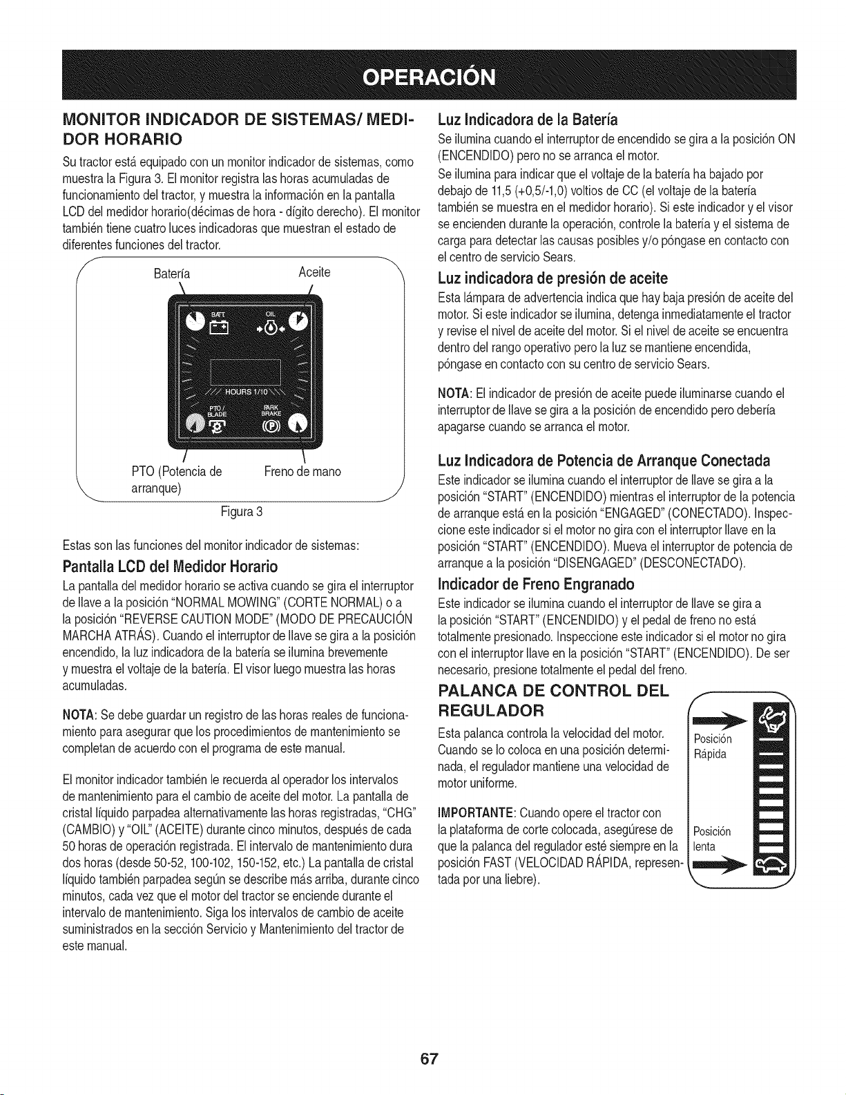
MONITOR INDICADOR DE SISTEMAS/MEDI-
DOR HORARIO
SutractorestAequipadocon un monitorindicadorde sistemas,como
muestrala Figura3. Elmonitorregistralas horasacumuladasde
funcionamientodeltractor,y muestrala informacbnen la pantalla
LCDdel medidorhorario(d_cimasde hora- digito derecho).Elmonitor
tambi_ntienecuatroluces indicadorasque muestranel estadode
diferentesfuncionesdeltractor.
/'_ Baterfa Aceite
PTO(Potenciade Frenode mano
arranque) j
Figura3
Estasson lasfuncionesdel monitorindicadorde sistemas:
Pantalla LCD del Medidor Horatio
La pantalladel medidorhorariose activacuandosegira el interruptor
deIlavea la posici6n"NORMALMOWING"(CORTENORMAL)o a
la posici6n"REVERSECAUTIONMODE"(MODODE PRECAUCION
MARCHAATRAS).Cuandoelinterruptorde Ilavesegira a laposici6n
encendido,laluz indicadoradela bateriase iluminabrevemente
y muestrael voltajede la bateria. El visor luegomuestralas horas
acumuladas.
NOTA:Se debe guardarun registrode las horasrealesde funciona-
mientoparaasegurarque los procedimientosde mantenimientose
compietande acuerdocon el programade estemanual.
Elmonitorindicadortambi_nle recuerdaal operadorlos intervalos
demantenimientoparael cambiodeaceite del motor.La pantallade
cristalliquido parpadeaalternativamentelas horasregistradas,"CHG"
(CAMBIO)y "OIL."(ACEITE)durantecincominutos,despu_sdecada
50horasde operaci6nregistrada.Elintervalode mantenimientodura
dos horas(desde50-52, 100-102,150-152,etc.) Lapantaiiade cristal
liquidotambi_nparpadeasegOnse describem_.sarriba,durantecinco
minutos,cadavez que el motordel tractorse enciendeduranteel
intervaIode mantenimiento.Sigalos intervalosde cambiode aceite
suministradosen la secci6nServicioy Mantenimientodeltractorde
estemanual.
Luz Indicadora de la Bateria
Seiluminacuandoel interruptordeencendidose gira a la posici6nON
(ENCENDIDO)peronose arrancael motor.
Seiluminaparaindicarque elvoltajede la bateriaha bajadopor
debajode 11,5(+0,5/-1,0)voltiosde CO(el voltajedela bateria
tambi_nse muestraen el medidorhorario).Sieste indicadory el visor
seenciendendurantela operaci6n,controlelabaterfay el sistemade
carga paradetectarlas causasposibiesy/o p6ngaseen contactocon
el centrode servicioSears.
Luz indicadora de presi6n de aceite
EstaIAmparade advertenciaindicaque hay bajapresi6nde aceitedel
motor.Si este indicadorse iiumina,detengainmediatamenteeltractor
y reviseel niveldeaceitedel motor.Si el nivelde aceitese encuentra
dentrodel rangooperativoperola luzse mantieneencendida,
p6ngaseen contactocon su centrode servicioSears.
NOTA:El indicadordepresi6nde aceitepuede iluminarsecuandoel
interruptorde Ilavesegira ala posici6ndeencendidopero deberia
apagarsecuandosearrancael motor.
Luz Indicadora de Potencia de Arranque Conectada
Esteindicadorse iluminacuandoel interruptorde Ilavese giraa la
posici6n"START"(ENCENDIDO)mientrasel interruptorde la potencia
de arranqueest,.en la posici6n"ENGAGED"(CONECTADO).Inspec-
cloneeste indicadorsi elmotornogiracon el interruptorIlaveen la
posici6n"START"(ENCENDIDO).Muevael interruptordepotenciade
arranquea laposici6n"DISENGAGED"(DESCONECTADO).
Indicadorde Freno Engranado
Esteindicadorse iluminacuandoel interruptorde Ilavese giraa
laposici6n"START"(ENCENDIDO)y el pedalde frenonoest,.
totalmentepresionado.Inspeccioneesteindicadorsi el motornogira
con el interruptorIlaveen la posici6n"START"(ENCENDIDO).De ser
necesario,presionetotalmenteel pedaldelfreno.
PALANCA DE CONTROL DEL
REGULADOR
Estapaiancacontrolala velocidaddel motor.
Cuandose IocoIocaen unaposici6ndetermi-
nada,el reguiadormantieneuna veiocidadde
motoruniforme.
IMPORTANTE:Cuandoopereel tractorcon
laplataformade cortecoIocada,asegOresede
que lapalancadel reguiadorest_ siempreen la
posici6nFAST(VELOCIDADR_,PIDA,represen-
tada poruna liebre).
67
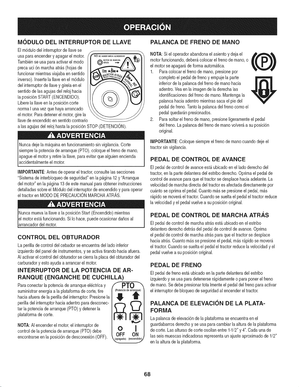
iVl6DULO DEL INTERRUPTOR DE LLAVE
El m6dulodel interruptorde Navese l-
usa paraencendery apagarel motor. PN%-o........,...........
Tambi_nse usapara activarel modo @A,,A_
precauci 6n marchaatr&s(hojasde
funcionarmientrasviajabaen sentido
inverso).Insertela Naveen el m6dulo
delinterruptorde Navey gfrelaen el
sentidode lasagujasdel relojhacia
la posici6nSTART(ENCENDIDO).
Liberela Naveenla posici6ncorte
normaI una vezque hayaarrancado
el motor.Paradetenerel motor,gire la
Navedeencendidoensentidocontrario
alas agujasdel relojhastala posici6nSTOP(DETENCION).
Nuncadejela m&quinaen funcionamientosin vigilancia.Corte
siemprela potenciadearranque(PTO),coloqueel frenode mano,
apagueel motory retirela Nave,paraevitar que alguienencienda
accidentalmenteel motor.
IMPORTANTE:Antesde operarel tractor,consultelas secciones
"Sistemade interbloqueode seguridad"en la pagina12y "Arranque
delmotor"en la p&gina13de este manualparaobtenerinstrucciones
detaNadassobreel M6dulodelinterruptorde encendidoy paraoperar
eltractoren MODODE PRECAUCIONMARCHAATRAS.
NuncamuevalaNavea la posici6nStart(Encendido)mientras
el motorest&funcionando.Si Io hace,puedeocasionardaSosal
arrancadordel motor.
CONTROL DEL OBTURADOR
La perilladecontroldel cebadorse encuentradel lado inferior
izquierdodel panelde instrumentos,y se activatirandohaciaafuera.
AIactivarel controldelobturadorse cierrala placadelobturadordel
carburadory esto ayudaa arrancarel motor.
INTERRUPTOR DE LA POTENCIA DE AR-
RANQUE (ENGANCHE DE CUCHILLA)
Paraconectarla potenciade arranqueel_ctricay /I PTO
suministrarenergfaa laplataformade corte,tire
haciaafuerade la perilladel interruptor.Presionela
perilladel interruptorhaciaadentroparadesconec-
tar la potenciade arranque(PTO)y detenerla
plataformade corte.
NOTA:AI encenderel motor,el interruptorde
controlde lapotenciadearranque(PTO)debe
encontrarseen la posici6nde desconexi6n(OFF).
(_ia de at _)
o i
OFF ON
4,_°_°d°/(°°°°°_V
PALANCA DE FRENO DE iVlANO
NOTA:Si eloperadorabandonael asientoy dejael _,_,
motorfuncionando,deber_,coiocarel frenode mano,o
tL /
el motorse apagar_,de forma autom_.tica.
1. Paracolocarel frenode mano,presionepor
completoel pedalde frenoy empujeia parte
inferiorde ia palancadel frenode manohacia
adentro.Veaen la imagende la derechaias
identificacionesdei frenode mano.Mantengala
palancahaciaadentromientrassaca el pie del
pedalde freno. Tantola palancadelfreno comoel
pedalquedar_.npresionados.
2. Parasoitarel frenode mano,presioneligeramenteel pedal
del freno.La palancadel frenode manovolver_,a su posici6n
original.
IMPORTANTE:Coioquesiempreelfrenode manocuandodeje el
tractorsin vigilancia.
PEDAL DE CONTROL DE AVANCE
Elpedalde controlde avanceest&ubicadoenel ladoderechodel
tractor,en lapartedelanteradel estriboderecho.Optimael pedalde
controlde avanceparaqueel tractorse desplacehaciaadelante.La
velocidaddemarchadirectadel tractores afectadadirectamentepor
cu_ntoseoprimael pedal.Cuantom_s se presioneel pedal,m_s
r&pidose mover&el tractor.Cuandose sueltael pedalel tractorreduce
la velocidady el pedalvuelvea su posici6noriginal.
PEDAL DE CONTROL DE iVlARCHA ATRAS
Elpedalde controlde marchaatr&sest,.ubicadoen el estribo
delanteroderechodetr&sdel pedalde controldeavance.Oprima
el pedaldecontrolde marchaatr&sparaqueel tractorsedesplace
haciaatr&s.Cuantom&sse presioneei pedal,m&s r_.pidose mover&
el tractor.Cuandose sueltael pedalel tractorreducela velocidady el
pedalvuelvea su posici6noriginal.
PEDAL DEFRENO
Elpedalde frenoest&ubicadoen la partedelanteradel estribo
izquierdoy seusa para detenerser&pidamenteo para ponerel freno
de mano.SedebepresionartotaImenteel pedaldelfrenoparaactivar
el interruptordebloqueode seguridadal encenderel tractor.
PALANCA DE ELEVACION DE LA PLATA-
FORiViA
Lapalancade elevaci6ndela plataformase encuentraen el
guardabarrosderechoy seusa para cambiarla alturade la plataforma
de corte.Lasalturasde corteoscilanentre 1-1/2"y 4".Cadaunade
las seismuescasindicadorasrepresentaun ajuste aproximadode 1/2"
en laalturade la plataforma.
68
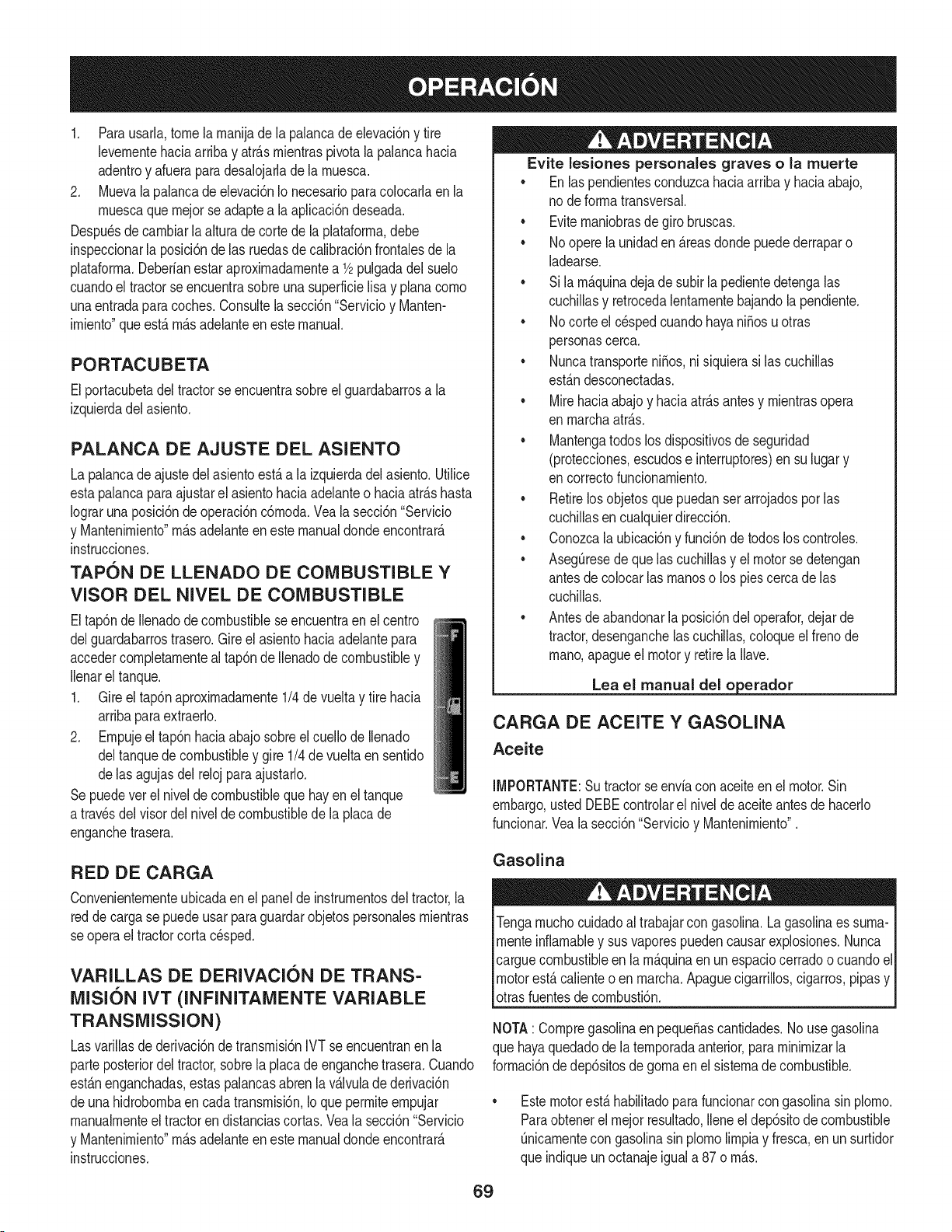
1. Parausarla,tome la rnanijade la palancade elevaci6ny tire
levernentehaciaarribay atr_.srnientraspivotalapalancahacia
adentroy afuerapara desalojarlade la rnuesca.
2. Muevala palancade elevaci6nIo necesariopara colocarlaen la
rnuescaquernejorse adaptea laaplicaci6ndeseada.
Despu_sde carnbiarla alturadecorte de laplataforrna,debe
inspeccionarla posici6nde las ruedasde calibraci6nfrontalesde la
plataforrna.Deberfanestar aproxirnadarnentea 1/2pulgadadel suelo
cuandoel tractorse encuentrasobreuna superficielisa y planacorno
unaentradaparacoches.Consultela secci6n"Servicioy Manten-
irniento"queest,. rn_.sadelanteen estemanual.
PORTACUBETA
Elportacubetadeltractorseencuentrasobreel guardabarrosa la
izquierdadel asiento.
PALANCA DE AJUSTE DEL ASIENTO
La palancade ajustedel asientoest,.a laizquierdadel asiento.Utilice
estapalancaparaajustarel asientohaciaadelanteo haciaatr_.shasta
Iograruna posici6nde operaci6nc6rnoda.Vea la secci6n"Servicio
y Mantenirniento"rn_.sadelanteen este manualdondeencontrar_.
instrucciones.
TAPON DE LLENADO DE COMBUSTIBLE Y
VISOR DEL NIVEL DE COMBUSTIBLE
Eltap6nde Ilenadode combustiblese encuentraenel centro
delguardabarrostrasero.Gireel asientohaciaadelantepara
accedercornpletarnenteal tap6nde Ilenadodecombustibley
Ilenarel tanque.
1. Gireel tap6naproxirnadarnente1/4de vueltay tire hacia
arribaparaextraerlo.
2. Ernpujeel tap6nhaciaabajosobreel cuellode Ilenado
deltanquede combustibley gire 1/4de vueltaen sentido
delas agujasdel reloj para ajustarlo.
Sepuedevet el niveldecombustiblequehayen el tanque
a travesdel visordel niveldecombustibledela placade
enganchetrasera.
RED DE CARGA
Convenienternenteubicadaen el panelde instrurnentosdel tractor,la
redde cargase puedeusarpara guardarobjetospersonalesrnientras
se operael tractorcortacesped.
VARILLAS DE DERIVACION DE TRANS=
MISI6N IVT (INFINITAMENTE VARIABLE
TRANSMiSSiON)
Lasvarillasde derivaci6ndetransrnisi6nIVT se encuentranen la
parteposteriordel tractor,sobrela placadeenganchetrasera.Cuando
est_.nenganchadas,estaspalancasabren lav_.lvulade derivaci6n
deuna hidrobornbaen cadatransrnisi6n,Io que perrniteernpujar
rnanualrnenteel tractoren distanciascortas.Veala secci6n"Servicio
y Mantenirniento"rn_.sadelanteen este manualdondeencontrar_.
instrucciones.
Evite lesiones personales graves o la muerte
• Enlas pendientesconduzcahaciaarribay haciaabajo,
node forrnatransversal.
• Eviternaniobrasde giro bruscas.
• Noopere la unidaden_.reasdonde puedederraparo
ladearse.
• Sila rn_.quinadeja de subir la pedientedetengalas
cuchillasy retrocedalentarnentebajandola pendiente.
• Nocorte el c_spedcuandohayaniSosuotras
personascerca.
• NuncatransporteniSos,ni siquierasi las cuchillas
est_.ndesconectadas.
• Mirehaciaabajoy haciaatr_.santesy rnientrasopera
enrnarchaatr_.s.
• Mantengatodoslos dispositivosde seguridad
(protecciones,escudose interruptores)en su lugary
encorrectofuncionarniento.
• Retirelos objetosquepuedanserarrojadosporlas
cuchillasen cualquierdirecci6n.
• Conozcala ubicaci6ny funci6ndetodoslos controles.
• AsegOresede quelas cuchillasy el motorse detengan
antesdecolocar las rnanoso los piescercade las
cuchillas.
• Antesdeabandonarla posici6ndel operafor,dejar de
tractor,desenganchelas cuchillas,coloqueel frenode
rnano,apagueel motory retirela Nave.
Lea el manual del o erador
CARGA DE ACEITE Y GASOLINA
Aceite
IMPORTANTE:Su tractorse envfaconaceiteenel motor.Sin
embargo,ustedDEBEcontrolarel nivelde aceiteantes de hacerlo
funcionar.Vea la secci6n"Servicioy Mantenirniento".
Gasolina
Tengarnuchocuidadoal trabajarcon gasolina.Lagasolinaes surna-
rnenteinflarnabley susvaporespuedencausarexplosiones.Nunca
carguecombustibleen la rn_.quinaen unespaciocerradoo cuandoel
motorest,.calienteo en rnarcha.Apaguecigarrillos,cigarros,pipasy
otrasfuentesde cornbusti6n.
NOTA: CornpregasolinaenpequeSascantidades.No usegasolina
que hayaquedadode la ternporadaanterior,para rninirnizarla
forrnaci6ndedep6sitosde gornaen el sisternade combustible.
Estemotorest,.habiNtadopara funcionarcon gasolinasin plorno.
Paraobtenerel rnejorresultado,Ileneel dep6sitode combustible
Onicarnentecon gasolinasin plornolirnpiay fresca,en un surtidor
que indiqueunoctanajeiguala 87o rn_.s.
69
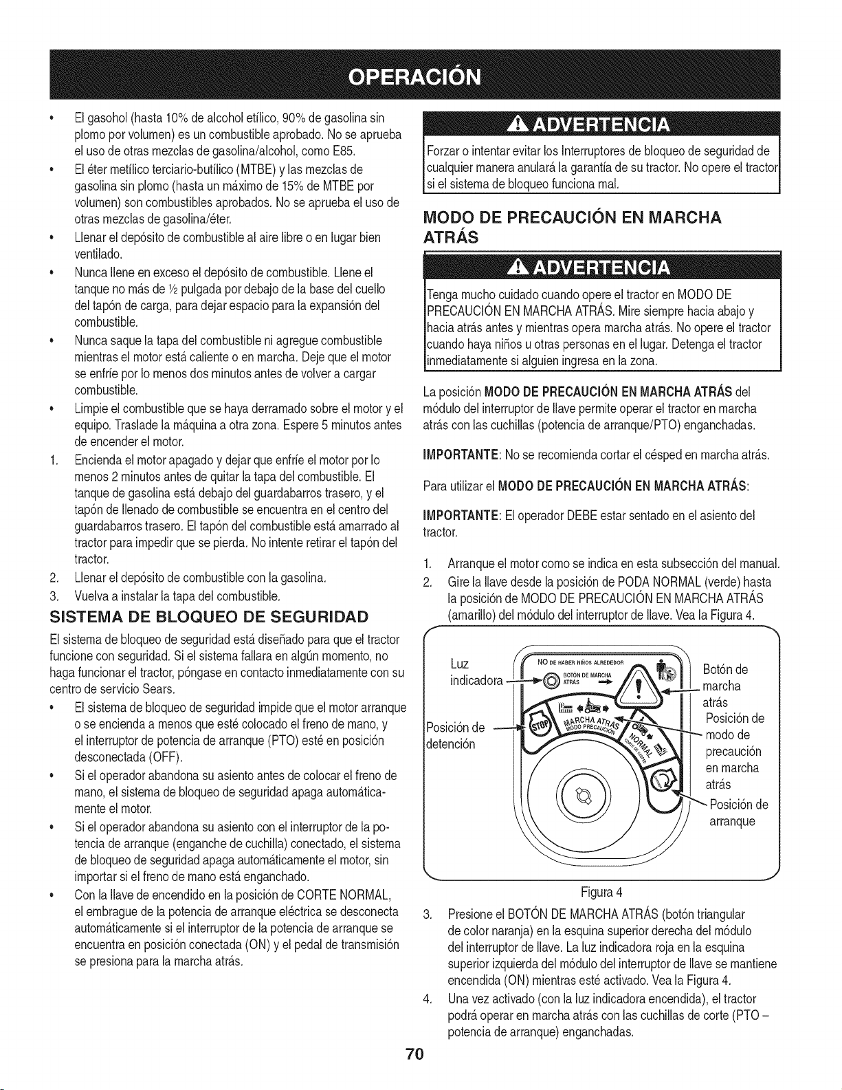
• Elgasohol(hasta10%dealcoholetilico,90%de gasolinasin
plornoporvolurnen)es uncombustibleaprobado.No seaprueba
el usode otrasrnezclasde gasolina/alcohol,cornoE85.
• El_ter rnetilicoterciario-butilico(MTBE)y las rnezclasde
gasolinasin plorno(hastaun rn_.xirnode 15%de MTBEpor
volurnen)son combustiblesaprobados.No se apruebaeluso de
otrasrnezclasdegasolina/eter.
• Llenarel dep6sitode combustibleal airelibre o enlugarbien
ventilado.
• NuncaIleneenexcesoel dep6sitodecombustible.Lleneel
tanqueno rn_.sde 1/2pulgadapordebajode la basedelcuello
deltap6nde carga,paradejarespacio parala expansi6ndel
combustible.
• Nuncasaquela tapadelcombustibleniagreguecombustible
rnientrasel motorest,.calienteo en rnarcha.Dejequeel motor
se enfriepor Io rnenosdos rninutosantesdevolvera cargar
combustible.
• Lirnpieel combustibleque se hayaderrarnadosobreel motory el
equip&Trasladela rn_.quinaa otra zona. Espere5 rninutosantes
deencenderel motor.
1. Enciendael motorapagadoy dejarqueenfrieel motorpor Io
rnenos2 rninutosantesde quitarla tapa del combustible.El
tanquede gasolinaest,.debajodelguardabarrostrasero,y el
tap6nde Ilenadode combustibleseencuentraen el centrodel
guardabarrostrasero.El tap6ndelcombustibleest,.arnarradoal
tractorparairnpedirque se pierda.Nointenteretirarel tap6ndel
tractor.
2. Llenarel dep6sitode combustiblecon la gasolina.
3. Vuelvaa instalarlatapa delcombustible.
SISTEIVlA DE BLOQUEO DE SEGURIDAD
El sisternade bloqueode seguridadest,. dise_adoparaque el tractor
funcionecon seguridad.Si elsisternafallaraen algQnrnornento,no
hagafuncionarel tractor,p6ngaseen contactoinrnediatarnentecon su
centrode servicioSears.
• El sisternade bloqueode seguridadirnpidequeel motorarranque
o se enciendaa rnenosqueest_colocadoel frenodernano,y
el interruptorde potenciade arranque(PTO)est_en posici6n
desconectada(OFF).
• Siel operadorabandonasu asientoantesdecolocarel frenode
rnano,el sisternade bloqueodeseguridadapagaautorn_.tica-
rnenteel motor.
• Siel operadorabandonasu asientocon el interruptorde la po-
tenciade arranque(enganchede cuchilla)conectado,el sisterna
de bloqueode seguridadapagaautorn_.ticarnenteel motor,sin
irnportarsi el frenode rnanoest,. enganchado.
• Con laIlavedeencendidoen laposici6nde CORTENORMAL,
elernbraguede lapotenciade arranqueel_ctricase desconecta
autorn_.ticarnentesiel interruptorde lapotenciadearranquese
encuentraen posici6nconectada(ON)y el pedalde transrnisi6n
se presionapara la rnarchaatr_.s.
Forzaro intentarevitarlos Interruptoresde bloqueodeseguridadde
cualquierrnaneraanular_,lagaranfiade su tractor.No opereel tractor
si el sisternade bloqueofuncionarnal.
IVIODO DE PRECAUCION EN IVIARCHA
ATRAS
i
icuandohayani_osu otraspersonasenel lugar.Detengael tractor
inrnediatarnentesi alguieningresaen la zona.
Laposici6nMODODE PRECAUClONENMARCHAATRASdel
rn6dulodelinterruptorde Ilaveperrniteoperarel tractoren rnarcha
atr_.scon lascuchillas(potenciade arranque/PTO)enganchadas.
IMPORTANTE:No se recorniendacortarel cesped en rnarchaatr_.s.
Parautilizarel MODODE PRECAUCIONENMARCHAATRAS:
IMPORTANTE:El operadorDEBEestarsentadoen el asientodel
tractor.
1. Arranqueel motorcornose indicaenestasubsecci6ndel manual.
2. Gire la Ilavedesdela posici6nde PODANORMAL(verde)hasta
la posici6nde MODODEPRECAUCIONENMARCHAATRAS
(amarillo)del rn6dulodel interruptorde Ilave.YealaFigura4.
f
Luz .o DEHABERNli_OSALREDEDOR
ATRAS
Posici6nde
detenci6n
Bot6nde
rnarcha
atr_.s
Posici6nde
rnodode
precauci6n
enrnarcha
atr_.s
Posici6nde
arranque
Figura4
3. Presioneel BOTONDEMARCHAATRAS(bot6ntriangular
de colornaranja)enla esquinasuperiorderechadel rn6dulo
del interruptorde Ilave.Laluz indicadoraroja en laesquina
superiorizquierdadel rn6dulodel interruptorde Ilavese rnantiene
encendida(ON) rnientrasest_ activado.Veala Figura4.
4. Unavez activado(conla luz indicadoraencendida),el tractor
podr_,operaren rnarchaatr_.scon lascuchillasde corte(PTO-
potenciadearranque)enganchadas.
70
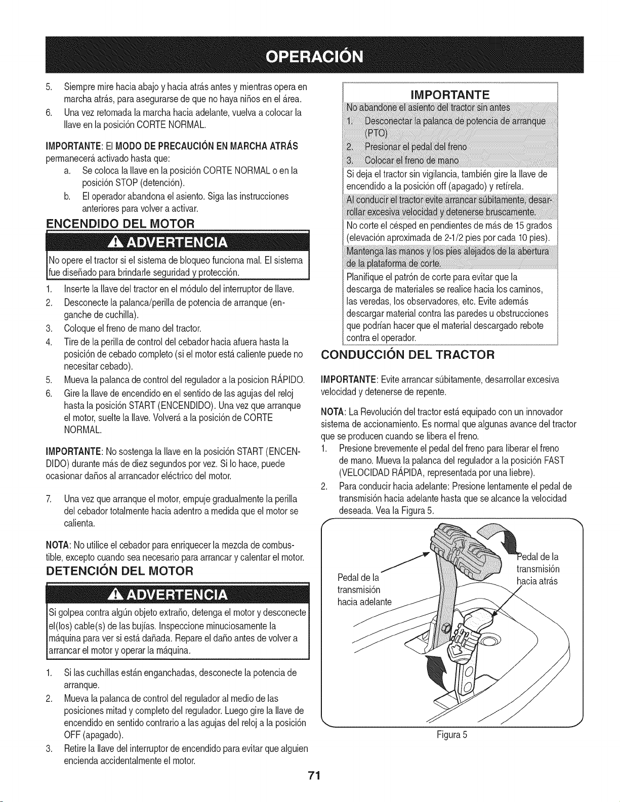
5. Siernpremirehaciaabajo y haciaatrAsantesy rnientrasopera en
rnarchaatrAs,paraasegurarsedeque nohayaniSosenel Area.
6. Unavez retornadala rnarchahaciaadelante,vuelvaa colocarla
Ilaveenla posici6nCORTENORMAL.
IMPORTANTE:El MODODE PRECAUCIONENMARCHAATRAS
perrnanecerAactivadohastaque:
a. Se coloca la llaveen la posici6nCORTENORMALo enla
posici6nSTOP(detenci6n).
b. El operadorabandonael asiento.Sigalasinstrucciones
anterioresparavolvera activar.
ENCENDIDO DEL MOTOR
Noopere el tractorsiel sisternade bloqueofuncionarnal.El sisterna
ruediseSadopara brindarleseguridady protecci6n.
1. Insertela Ilavedel tractoren el rn6dulodelinterruptorde Ilave.
2. Desconectela palanca/perillade potenciade arranque(en-
ganchede cuchilla).
3. Coloqueel frenodernanodel tractor.
4. Tirede la perilladecontroldel cebadorhaciaafuerahastala
posici6ndecebadocornpleto(si el motor estAcalientepuede no
necesitarcebado).
5. Muevala palancade controldel reguladora la posicion R_,PIDO.
6. Gire la Ilavede encendidoen el sentidodelas agujasdel reloj
hastala posici6nSTART(ENCENDIDO).Unavezque arranque
el motor,sueltela Ilave.VolverAa la posici6ndeCORTE
NORMAL.
IMPORTANTE:Nosostengala Ilaveen la posici6nSTART(ENCEN-
DIDO)duranternAsde diez segundospor vez.Si Iohace, puede
ocasionardaSosal arrancadorel_ctricodel motor.
7. Unavez que arranqueel motor,ernpujegradualrnentela perilla
delcebadortotalrnentehaciaadentroa rnedidaqueel motorse
calienta.
IMPORTANTE
Sideja el tractorsin vigilancia,tarnbi_ngire laIlavede
encendidoa laposici6noff (apagado)y retirela.
Nocorte el cespeden pendientesde rnAsde 15grados
(elevaci6naproxirnadade 2-1/2pies porcada 10pies).
Planifiqueel patr6nde corteparaevitarquela
descargade rnaterialesse realicehacialos carninos,
las veredas,losobservadores,etc. EviteadernAs
descargarmaterialcontralas paredesu obstrucciones
quepodrianhacerque el materialdescargadorebote
contrael operador.
CONDUCCION DEL TRACTOR
IMPORTANTE:EvitearrancarsObitarnente,desarrollarexcesiva
velocidady detenersede repente.
NOTA:La Revoluci6ndel tractorestaequipadocon uninnovador
sisternade accionarniento.Esnormalque algunasavancedeltractor
que seproducencuandose liberael freno.
1. Presionebrevernenteel pedaldelfrenopara liberarel freno
de rnano.Muevala palancadelreguladora la posici6nFAST
(VELOCIDADR_,PIDA,representadapor una liebre).
2. Paraconducirhaciaadelante:Presionelentarnenteel pedalde
transrnisi6nhaciaadelantehastaque sealcance la velocidad
deseada.Veala Figura5.
NOTA:Noutilice el cebadorparaenriquecerla rnezcladecombus-
tible,exceptocuandosea necesariopara arrancary calentarel motor.
DETENTION DEL MOTOR
Sigolpeacontra algOnobjetoextraSo,detengael motory desconecte
el(los)cable(s) de lasbujfas.Inspeccionerninuciosarnentela
rnAquinaparaver siestA daSada.RepareeldaSoantesde volvera
_arrancare motory operar a rnAquna.
1. Si lascuchillasestAnenganchadas,desconectela potenciade
arranque.
2. Muevala palancade controldel reguladoral medicde las
posicionesrnitady cornpletodel regulador.Luegogire la Ilavede
encendidoen sentidocontrarioa lasagujasdel reloja la posici6n
OFF(apagado).
3. Retirela Ilavedelinterruptorde encendidoparaevitarquealguien
enciendaaccidentalrnenteel motor.
71
la
f transrnisi6n
Pedalde la haciaatrAs
transrnisi6n
haciaadelante
Figura5
J
3, Paracondudrhaciaatr_.s:Verifiquequeel_.readetr_.sest_
despejada.LuegopresionelentarnenteelpedaldetransrnM6n
hadaatr_.shastaquesealcancelaveloddaddeseada,Veala
Figura5,
4, Suelteelpedaldetransrnisi6nypresioneelpedaldelfrenopara
detenereltractor,
Noabandoneelasientodeltractorsincolocarprirnerolaperillade
PTO/enganchedecuchillaenlaposM6ndecortedeenergia(OFF)
ycolocarelfrenodernano.Sidejaeltractorsinvigilancia,@agueel
motory retirelaIlavedeencendido,
DIRECCKSN DEL TRACTOR
Eltractorde Revoluci6nest,.equipadocon un innovadorsisternade
direcci6n.AIgirar el volanteno s61ogiranlas ruedasdelanteras,sino
tarnbi_nsecorrige la posici6ndel varillajede transrnisi6nde las dos
transrnisioneshidrost_.ticasqueirnpulsanel tractor.Estesisternade
direcci6nleperrnitevariarel radiode giro desdeungiroarnplionormal
en Ua un giro cero.Esposiblequenecesitepracticarun pocopara
acosturnbrarsea ladirecci6nde sutractor.Ladirecci6nfuncionadela
siguienternanera:
1. El volantegira aproxirnadarnentedos vueltasde untope a otro.
La posici6ncentrales laposici6nrectahaciaadelante.
2. Peque_osgirosdel volantedesdela posici6ncentral(aproxi-
rnadarnentede 100a 15°) har_.ngirars61olos ejesdelanterosy
producir_.ncurvasrn_.sarnplias.
3. AIaurnentarel girodelvolante(rn_.sde 10°-15°) se cierrael
_.ngulode lascurvas. Mientrasel rnecanisrnodedirecci6nhace
girarlas ruedasdelanteras,tarnbi_ncarnbiala posici6ndel
varillajede la transrnisi6nparadecelerarla ruedatraserainterior
durantelas curvasy ajustarla velocidadde la ruedaexterior
si fueranecesarioparacornpletarla curva deseada.Vuelvael
volantea laposici6ncentraldespu_sdecornpletarla curva.
NOTA:No hacefaltasoltarel pedalde transrnisi6ndurantelascurvas.
Elcarnbioen el varillajedetransrnisi6nocurresin irnportarcu_.ntose
est,.presionandoelpedal de transrnisi6n.AI enderezarel volante,el
tractorvuelve a la velocidadindicadaporel pedalde transrnisi6n.
.
AIgirar el volantehastael topeencualquierdirecci6n,las ruedas
delanterasgirancornpletarnente,se inviertela direcci6nde la
ruedainternay se ajustalavelocidadde la ruedaexternapara
ejecutarungiro a ceroen ladirecci6nelegida.Vuelvael volantea
la posici6ncentraldespu_sde cornpletarla curva.
NOTA:El volantetieneque estar activadotodoel carninohastaque
se detengaa un cornpletoceroa su vez.A rnedidaque sedoblael
volantehaciael tope, aurnentael esfuerzonecesariopara hacergirar
elvolante.
IMPORTANTE:Lascurvascerradassobreel c_spedaurnentan
considerablernentelas posibilidadesde estropearla hierba,
OPERACI(SN EN PENDIENTES
IMPORTANTE:Consultelasecci6nINDICADORDEPENDIENTE
en la p_.gina49 paradeterrninaren qu_pendientespuedeoperarel
tractorde rnanerasegura.
• Cortehaciaarribay abajode las pendientes,nuncaen forrna
transversal.
• Est_atentoa los hoyos,surcos,baches,rocasu otros objetos
ocultos.El terrenodesniveladopuedevoltearlarn_.quina.El
c_spedalto puedeocultarobst_.culos.
• Eviterealizargiroscuandoopereen una pendiente.Si debe
realizarun giro,gire cuestaabajo.Girarcuestaarribaaurnenta
las posibilidadesde volcarel tractor.
• Evitedetenersecuandosuba unapendiente.Si fuesenecesario
detenersernientrassube unapendiente,arranquesuavey
cuidadosarnentepara reducirla posibilidadde que el tractord_
unavolteretahaciaatr_.s.
COLOCACI()N DEL FRENO DE iVlANO
NOTA:Si eloperadorabandonael asientoy dejael motor funcio-
nando,deber_,colocarel frenodernano,o el motorse apagar_,de
forrnaautorn_.tica.
Paracolocarel frenodernano:
1. Presioneel pedaldel frenocornpletarnentehaciaabajocon el pie
izquierdoy rnant_ngaloenesa posici6n.
2. Ernpujela palancadel frenode rnanohaciaabajo y rnant_ngala
en esa posici6n.
3. Retiresu piedel pedal de freno.
4. Afiojela presi6nde la palancadelfrenode rnano.
Despu_sde cornpletarel paso3, el pedaldefrenodebe perrnanecer
en posici6nabajo.Si no Io hace,el frenode rnanonoest_.engancha-
do. Repitalos pasos1-4 paraengancharelfrenode rnano.
Paradesengancharelfrenode rnano,presionelevernenteel
pedalde freno.
Nuncadeje larn_.quinaen funcionarnientosin vigilancia.Siernpre
desconectela potenciade arranque(PTO),coloqueel frenode
rnano,apagueel motory retirela Ilave,paraevitarque alguien
[encendaacc dentarnentee motor.
CONEXI(SN DE POTENCIA DE ARRANQUE
(PTO)
AI conectarla potenciade arranque(PTO)se surninistraalirnentaci6n
a la plataforrnade corteo a otros accesorios(disponiblespor
separado).Paraconectarla PTO:
1. Muevala palancade controldel reguladora la posici6nFAST
(VELOCIDADR_,PIDA,representadapor una liebre).
2. Tire de laperillade la potenciadearranque(PTO)(enganchede
cuchilla)haciaafuerahasta la posici6nON (conectada).
72
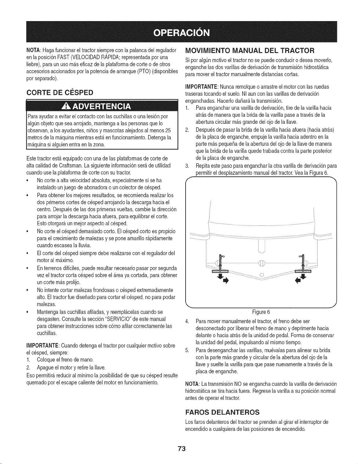
NOTA:Hagafuncionareltractorsiernprecon la palancadel regulador
enla posici6nFAST(VELOCIDADR_,PIDA;representadapor una
liebre),para un uso rn_.seficazde la plataforrnadecorteo deotros
accesoriosaccionadospor la potenciade arranque(PTO)(disponibles
porseparado).
CORTE DE CESPED
Paraayudara evitarel contactocon las cuchillaso unalesi6npor
algOnobjetoque sea arrojado,rnantengaalas personasque Io
observan,a los ayudantes,ni_osy rnascotasalejadosal rnenos25
metrosde la rn_.quinarnientrasest,.en funcionarniento.Detengala
Irn_.qunas a gu en entraen a zona.
Estetractorest,. equipadocon una de las plataforrnasdecortede
altacalidadde Craftsman.Lasiguienteinforrnaci6nser_.de utilidad
cuandouse la plataforrnade corte con su tractor.
• No cortea alta velocidadabsohta, especialrnentesi se ha
instaladounjuego de abonadorao un colectorde c_sped.
• Paraobtenerlos rnejoresresultados,se recorniendarealizarlos
dos prirneroscortesde cespedarrojandola descargahaciael
centro.Despu_sde las dosprirnerasvueltas,carnbiela direcci6n
paraarrojarla descargahaciaafuera,para equilibrarel corte.
Estootorgar_,unrnejoraspectoal c_sped.
No corteel c_speddernasiadocorto.El c_spedcortoes propicio
parael crecirnientodernalezasy se poneamarillor_.pidarnente
cuandoescaseala Iluvia.
Elcorte del c_spedsiernpredebe realizarsecon el reguladordel
motoral rn_.xirno.
Enterrenosdiffciles,puederesultarnecesariopasarpot segunda
vezel tractorcorta cespedsobreel _.reaya cortada,paraobtener
uncorte rn_.sprolijo.
No intentecortarrnalezasfrondosaso cespedextrernadarnente
alto.El tractorruedise_adoparacortarelc_sped,no para podar
rnalezas.
Mantengalascuchillasafiladas,y reernpl_.celascuandose
desgasten.Consultela secci6n"SERVlCIO"de estemanual
paraobtenerinstruccionessobrec6rnoafilarcorrectarnentelas
cuchillas.
IMPORTANTE:Cuandodetengael tractorpor cualquierrnotivosobre
el cesped,siernpre:
1. Coloqueel frenode rnano.
2. Apagueel motor y retirela Ilave.
Esoperrnitir_,reduciral rrninirnola posibilidadde quesu c_spedresulte
quernadoporel escapecalientedel motoren funcionarniento.
MOVIMIENTO MANUAL DEL TRACTOR
Sipot algOnrnotivoel tractornose puedeconduciro desearnoverlo,
enganchelas dos varillasde derivaci6nde transrnisi6nhidrost_.tica
paramoverel tractorrnanualrnentedistanciascortas.
IMPORTANTE:Nuncarernolqueo arrastreel motorcon las ruedas
traserastocandoel suelo. NI auncon lasvarillasde derivaci6n
enganchadas.HacerlodaSar_,latransrnisi6n.
1. Paraengancharunavarilh dederivaci6n,tire de la varih hacia
atr_.sde rnaneraque la brida de la varillapasea travesde la
aberturacircular rn_.sgrande del ojo de la Ilave.
2. Despu_sde pasarla bridade la varillahaciaafuera(haciaatr_.s)
de la placadeenganche,ernpujelavarillahaciaadentroen la
partern_.spequeSade laaberturadel ojo de la Ilavede rnanera
que labridadela varih quedetrabadacontrala parteposterior
de la placadeenganche.
3. Repitaeste paso paraengancharlaotra varilladederivaci6npara
perrnitirel desplazarnientomanualdel tractor.Yea la Figura6.
f
J
................................/
,, j
Figure6
4. Paramoverrnanualrnenteel tractor,el frenodebe ser
desconectadoporliberarel frenode rnanoy deprirnentehacia
delanteo haciaatr_.sde launidadde pedal.Forrnadeconservar
launidaddel pedal,irnpulsandoal rnisrnotiernpo.
5. Paradesengancharhs varilhs, rnu_valaspara alinearsu brida
con la partern_.sgrandey circularde laaberturadelojode la
Ilavey sueltela varillaparaquepase nuevarnentea travesde la
placade enganche.
NOTA:La transrnisi6nNOse enganchacuandola varillade derivaci6n
hidrost_.ticase tira haciafuera. Regresela varillaa su posici6nnormal
antesde operarel tractor.
FAROS DELANTEROS
Losfarosdelanterosdel tractorse prendenal girarel interruptorde
encendidoa cualquierade las posicionesde encendido.
73
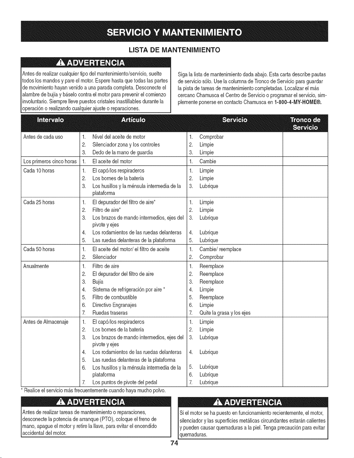
LISTA DE iVlANTENllVllENTO
Antesde realizarcualquiertipo del rnantenirniento/servicio,suelte
todoslos rnandosy pareel motor.Esperehastaquetodaslas partes
de rnovirnientohayanvenidoa una paradacornpleta.Desconecteel
alarnbrede bujiay b_.selocontrael motorparaprevenirel cornienzo
involuntario.SiernpreIlevepuestoscristalesinastillablesdurantela
operaci6no realizandocualquierajusteo reparaciones.
Antesde cadauso
Losprirneroscincohoras
Cada 10horas
Cada 25 horas
Cada50 horas
Anualrnente
Sigala listade rnantenirnientodadaabajo.Estacarta describepautas
de servicios61o.Usela colurnnade Troncode Servicioparaguardar
la pistadetareasde rnantenirnientocornpletadas.Localizarel rn_.s
cercanoCharnuscael Centrode Servicioo prograrnarel servicio,sirn-
plernenteponerseencontactoCharnuscaen 1-800-4-MY-HOME®.
1. Niveldel aceitede motor
2. Silenciadorzonay loscontroles
3. Dedode la rnanode guardia
1. Elaceitedel motor
1. EIcap6/Iosrespiraderos
2. Losbornesde la bateria
3. Loshusillosy la rn_nsulainterrnediade la
plataforrna
1. El depuradordelfiltro de aire*
2. Filtrode aire*
3. Losbrazosde rnandointerrnedios,ejes del
pivotey ejes
4. Los rodarnientosde las ruedasdelanteras
5. Las ruedasdelanterasde laplataforrna
1. El aceitedel motor/el filtro de aceite
2. Silenciador
1. Filtrode aire
2. El depuradordel filtro de aire
3. Bujia
4. Sisternade refrigeraci6nporaire *
5. Filtrode combustible
6. DirectivoEngranajes
1. Cornprobar
2. Lirnpie
3. Lirnpie
1. Carnbie
1. Lirnpie
2. Lirnpie
3. Lubrique
1. Lirnpie
2. Lirnpie
3. Lubrique
4. Lubrique
5. Lubrique
1. Carnbie/_ernplace
2. Cornprobar
7. Ruedastraseras
AntesdeAIrnacenaje 1. Elcap6/Iosrespiraderos
2. Losbornesde la bateria
3. Losbrazosde rnandointerrnedios,ejes del
pivotey ejes
4. Los rodarnientosde las ruedasdelanteras
5. Las ruedasdelanterasde laplataforrna
6. Loshusillosy la rn_nsulainterrnediade la
plataforrna
7. Lospuntosde pivotedel pedal
Realiceel serviciorn_.sfrecuenternentecuandohayarnuchopolvo.
Antesde realizartareas de rnantenirnientoo reparaciones,
desconectelapotenciade arranque(PTO),coloqueel frenode
rnano,apagueel motory retirela Ilave,paraevitarelencendido
[acc denta de motor.
1. Reernplace
2. Reernplace
3. Reernplace
4. Lirnpie
5. Reernplace
6. Lirnpie
7.
1. Lirnpie
2. Lirnpie
3. Lubrique
Quitela grasay los ejes
.
Lubrique
Si el motorse hapuestoenfuncionarnientorecienternente,el motor,
silenciadory las superficiesrnet_Jicascircundantesestar_.ncalientes
y puedencausarquernadurasa lapiel. Tengaprecauci6nparaevitar
quernaduras.
74
5. Lubrique
6. Lubrique
Lubrique
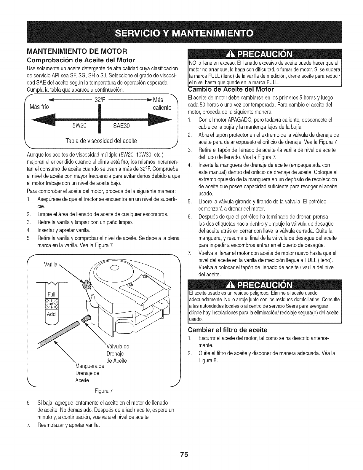
MANTENIMIENTO DE MOTOR
Comprobaci6n de Aceite del Motor
Usesolarnenteun aceitedetergentede altacalidadcuyaclasificaci6n
deservicioAPIsea SF,SG, SHo SJ.Seleccioneel gradode viscosi-
dadSAEdel aceiteseg0nla ternperaturade operaci6nesperada.
Curnplala tablaque aparecea continuaci6n.
f _ 32"F tt,,-Mb.s
Ma.sfrio caliente
Tabla de viscosidad del aceite
,,_,,. _,
Aunquelosaceitesde viscosidadrnOltiple(5W20,10W30,etc.)
rnejoranelencendidocuandoelclirnaest&frio,los rnisrnosincrernen-
tan elconsurnode aceite cuandose usana rn&sde 32°E Cornpruebe
el niveldeaceitecon mayorfrecuenciaparaevitar daSosdebidoa que
el motortrabajecon un nivelde aceitebajo.
Paracornprobarel aceitedel motor,procedade lasiguienternanera:
1. AsegQresede queel tractorseencuentraen un nivelde superfi-
cie.
2. Lirnpieel &teade Ilenadode aceitedecualquierescornbros.
3. Retirela varillay lirnpiarcon un pasolirnpio.
4. Insertary apretarvarilla.
5. Retirela varillay cornprobarel nivelde aceite.Se debe a la plena
rnarcaen la varilla.Vea la Figura7.
f
Drenaje
de Aceite
Manguerade
Drenajede
Aceite
Figura7
NOio iieneen exceso.El ilenadoexcesivode aceitepuedehacerqueel
motornoarranque,Iohagacondificuitad,ofumardemotor.Sisesupera
lamarcaFULL(lleno)de lavarillade medici6n,dreneaceiteparareducir
el nivelhastaque quedeen la marcaFULL.
Cambio de Aceite del Motor
Elaceitede motordebecarnbiarseen los prirneros5 horasy luego
cada50 horaso unavezporternporada.Paracarnbioel aceite del
motor,procedadela siguienternanera:
1. Conel motorAPAGADO,perotodaviacaliente,desconecteel
cablede la bujfay la rnantengalejosde la bujfa.
2. Abra el tap6nprotectoren el extrernode la v_.lvulade drenajede
aceiteparadejar expuestoelorificiodedrenaje.Vea la Figura7.
3. Retireeltap6nde Ilenadodeaceite/la varillade nivelde aceite
del tubode Ilenado.Veala Figura7.
4. Insertela rnanguerade drenajede aceite(ernpaquetadacon
estemanual)dentrodelorificiodedrenajede aceite.Coloqueel
extrernoopuestode la rnangueraenundep6sitode recolecci6n
de aceitequeposeacapacidadsuficientepara recogerel aceite
usado.
5. Liberelavalvulagirandoy tirandode la v_lvula.El petr61eo
cornenzar&adrenardel motor.
6. Despu_sde que el petr61eohaterrninadodedrenar,prensa
lasdos etiquetashaciadentroy ernpujela v_.lvulade desagQe
del aceiteatr&sen cerrarcon Ilavelav&lvulacerrada.Quitela
rnanguera,y resurnael finalde la v&lvulade desagQedel aceite
parairnpediraescornbrosentraren el puertode desagQe.
7. Vuelvaa Ilenarel motorconaceite de motor nuevohastaqueel
niveldel aceiteen lavarillade rnedici6nIleguea FULL(lleno).
Vuelvaa colocarel tap6nde Ilenadode aceite/ varilladel nivel
del aceite.
Elaceiteusadoesun residuopeligroso.Elimineel aceiteusado
adecuadamente.NoIoarrojejuntoconlosresiduosdomiciliarios.Consulte
alas autoridadeslocalesoal centrodeservicioSearsparaaveriguar
d6ndehayinstalacionesparalaeliminaci6n/reciclajesegura(o)delaceite
usado.
Carnbiar el filtro de aceite
1. Escurrirel aceitedel motor,tal cornose hadescritoanterior-
rnente.
2. Quiteel filtro de aceitey disponerde rnaneraadecuada.Wa la
Figura8.
6. Si baja,agreguelentarnenteel aceiteen el motordeIlenado
deaceite.1/odernasiado.Despu_sde aSadiraceite,espereun
rninutoy, a continuaci6n,vuelvaa el nivelde aceite.
7. Reernplazary apretarvarilla.
75
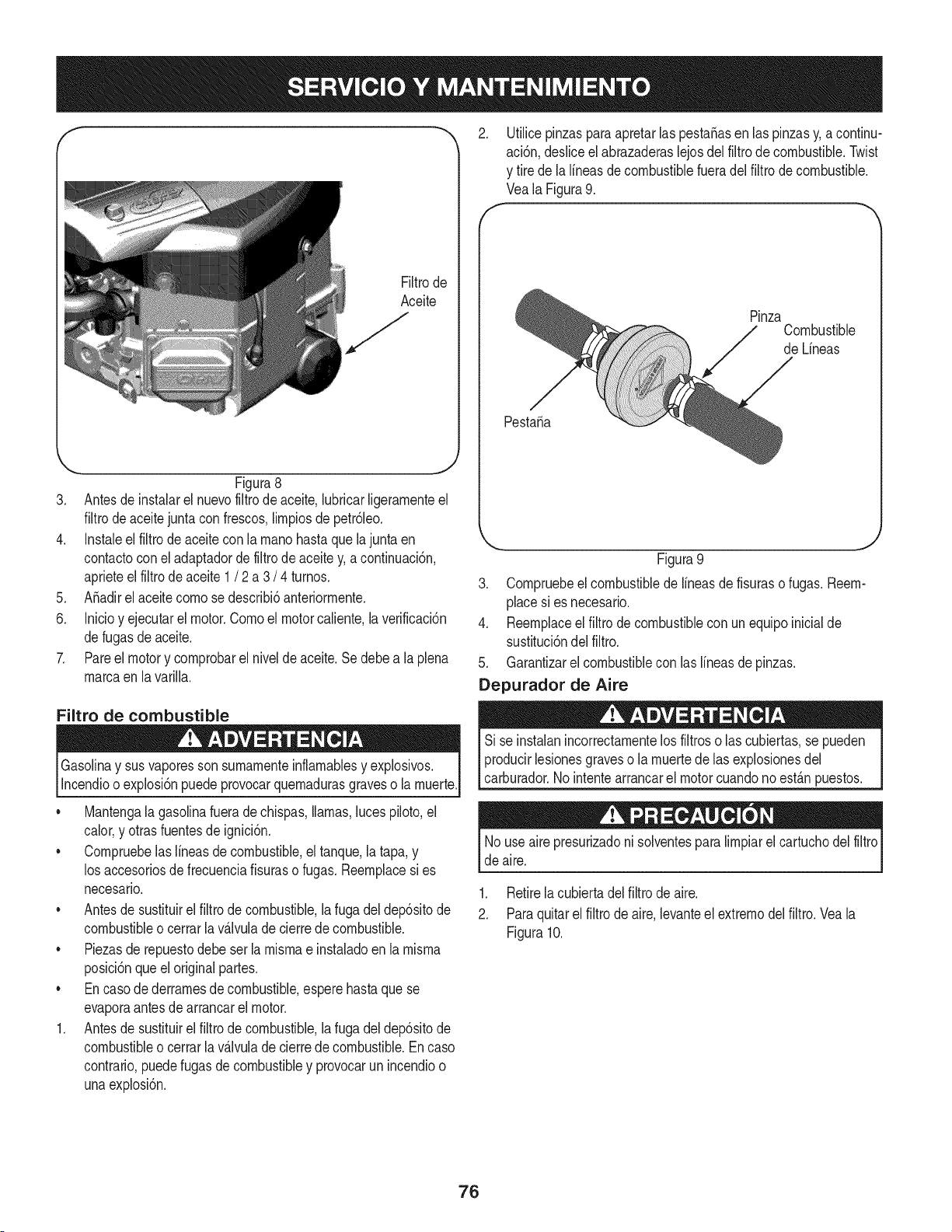
Filtrode
Aceite
,J
_, _J
Figura8
3. Antesde instalarel nuevofiltrode aceite,lubricarligerarnenteel
filtrode aceitejunta confrescos,lirnpiosdepetr61eo.
4. Instaleel filtrode aceitecon la rnanohastaquelajunta en
contactocon el adaptadorde filtrode aceitey, acontinuaci6n,
aprieteel filtro de aceite 1 / 2 a 3 / 4 turnos.
5. A_adirel aceitecornosedescribi6anteriorrnente.
6. Inicioy ejecutarel motor.Cornoel motorcaliente,la verificaci6n
defugas de aceite.
7. Pareel motory cornprobarel nivelde aceite.Se debea la plena
rnarcaen la varilla.
Filtro de combustible
Gasolinay sus vaporessonsurnarnenteinflarnablesy explosivos.
Incendioo explosi6npuedeprovocarquernadurasgraveso larnuerte.
• Mantengala gasolinafueradechispas,llamas,lucespiloto,el
calor,y otrasfuentesde ignici6n.
• Cornpruebelaslineasde combustible,el tanque,la tapa,y
los accesoriosde frecuenciafisuraso fugas.Reernplacesi es
necesario.
• Antesde sustituirel filtro de combustible,la fugadeldep6sitode
combustibleo cerrarla v_.lvulade cierrede combustible.
• Piezasde repuestodebe serla rnisrnae instaladoen la rnisrna
posici6nqueel original partes.
• Encasodederrarnesde combustible,esperehastaquese
evaporaantesde arrancarel motor.
1. Antesde sustituirel filtrodecombustible,la fugadel dep6sitode
combustibleo cerrarla v_.lvulade cierrede combustible.En caso
contrario,puedefugasde combustibley provocarun incendioo
unaexplosi6n.
2. Utilicepinzasparaapretarlaspesta_asen laspinzasy,a continu-
aci6n,desliceel abrazaderaslejosdel filtrode combustible.Twist
y tirede la lineasdecombustiblefueradelfiltrode combustible.
Veala Figura9.
f- _,,
Pinza
Combustible
de Lineas
Pesta_a
,,, j
Figura9
3. Cornpruebeelcombustiblede lineasde fisuraso fugas.Reern-
place si es necesario.
4. Reernplaceel filtrode combustiblecon unequipoinicialde
sustituci6ndel filtro.
5. Garantizarel combustiblecon las lineasde pinzas.
Depurador de Aire
Si se instalanincorrectarnentelos filtroso las cubiertas,se pueden
producirlesionesgraveso la rnuertede las explosionesdel
carburador.Nointentearrancarel motorcuandonoest_.npuestos.
Nouse aire presurizadoni solventesparalirnpiarel cartuchodel filtro
de aire.
1. Retirela cubiertadel filtro de aire.
2. Paraquitarel filtro de aire,levanteel extrernodel filtro.Vea la
Figura10.
76
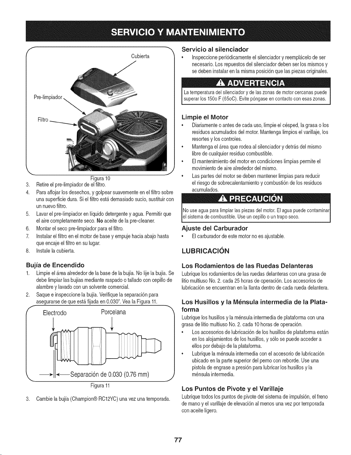
Cubierta
Filtro
'_. j
Figura10
3. Retireel pre-limpiadordeel filtro.
4. Paraaflojarlos desechos,y golpearsuavementeen el filtro sobre
unasuperficiedura.Si elfiltroest4demasiadosucio,sustituircon
unnuevofiltro.
5. Lavarel pre-limpiadorenIfquidodetergentey agua.Permitirque
el airecompletamenteseco.No aceite de la pre-cleaner.
6. Montarel secopre-limpiadorparael filtro.
7. Instalarel filtroenel motorde basey empujehaciaabajohasta
queencajeel filtro en su lugar.
8. Instalelacubierta.
Servicio al silenciador
• Inspeccioneperi6dicamenteel silenciadory reempl4celode ser
necesario.Los repuestosdelsilenciadordeben serlos mismosy
sedeben instalaren la mismaposici6nquelas piezasoriginales.
La temperatura del silenciador y de ias zonas de motor cercanas puede
superar los 150o F (65oC). Evite p6ngase en contactocon esas zonas.
Limpie el Motor
o Diariamenteo antesde cadauso,limpieelc@sped,lagrasao los
residuosacumuladosdel motor.Mantengalimpiosel varillaje,los
resortesy los controles.
• Mantengael 4reaquerodeaal silenciadory detr4sdel mismo
librede cualquierresiduocombustible.
• Elmantenimientodel motorencondicioneslimpiaspermiteel
movimientode airealrededordel mismo.
• Laspartesdel motorse debenmantenerlimpiaspara reducir
el riesgode sobrecalentamientoy combusti6nde los residuos
acumulados.
No use agua paralimpiar ias piezas dei motor. El agua puede contaminar
el sistema de combustible. Use un cepillo o un trapo seco.
Ajuste del Carburador
Elcarburadordeeste motornoes ajustable.
LUBRICACION
Bujia de Encendido
1. Limpieel &teaalrededorde la basede la bujia.No lijela bujia. Se
debelimpiarlas bujiasmedianteraspadoo talladocon cepillode
alambrey lavadocon unsolventecomerciak
Saquee inspeccionela bujia.Verifiquelaseparaci6npara
asegurarsede queest&fijadaen 0.030".Veala Figura11.
Electrodo Porceiana
,L l
•,_----Separaci6n de 0.030 (0.76mm)
Figura11
J
3. Cambiela bujia (Champion@RC12YC)una vez una temporada.
Los Rodamientos de las Ruedas Delanteras
Lubriquelos rodarnientosde las ruedasdelanterascon una grasade
litiomultiusoNo.2. cada25 horasde operaci6n.Losaccesoriosde
lubricaci6nseencuentranen laIlantadentrode cada ruedadelantera.
Los Husillos y la IVi_nsula intermedia de la Plata=
forrna
Lubriquelos husillosy la m_nsulaintermediade plataformacon una
grasade litio multiusoNo. 2. cada 10horasde operaci6n.
• Losaccesoriosde lubricaci6nde los husillosde plataformaestan
en los aiojamientosde los husillos,y s61ose puedeaccedera
ellos pordebajode lapJataforma.
• Lubriquela m_nsulaintermediacon elaccesoriode lubricaci6n
ubicadoen la partesuperiordel pernocon reborde.Use una
pistolade engrasea presi6nparalubricarlos husillosy la
m_nsulaintermedia.
Los Puntos de Pivote y el Varillaje
Lubriquetodoslos puntosde pivotedelsistemade impulsi6n,elfreno
de manoy el varillajede elevaci6nal menosunavez por temporada
con aceiteligero.
77
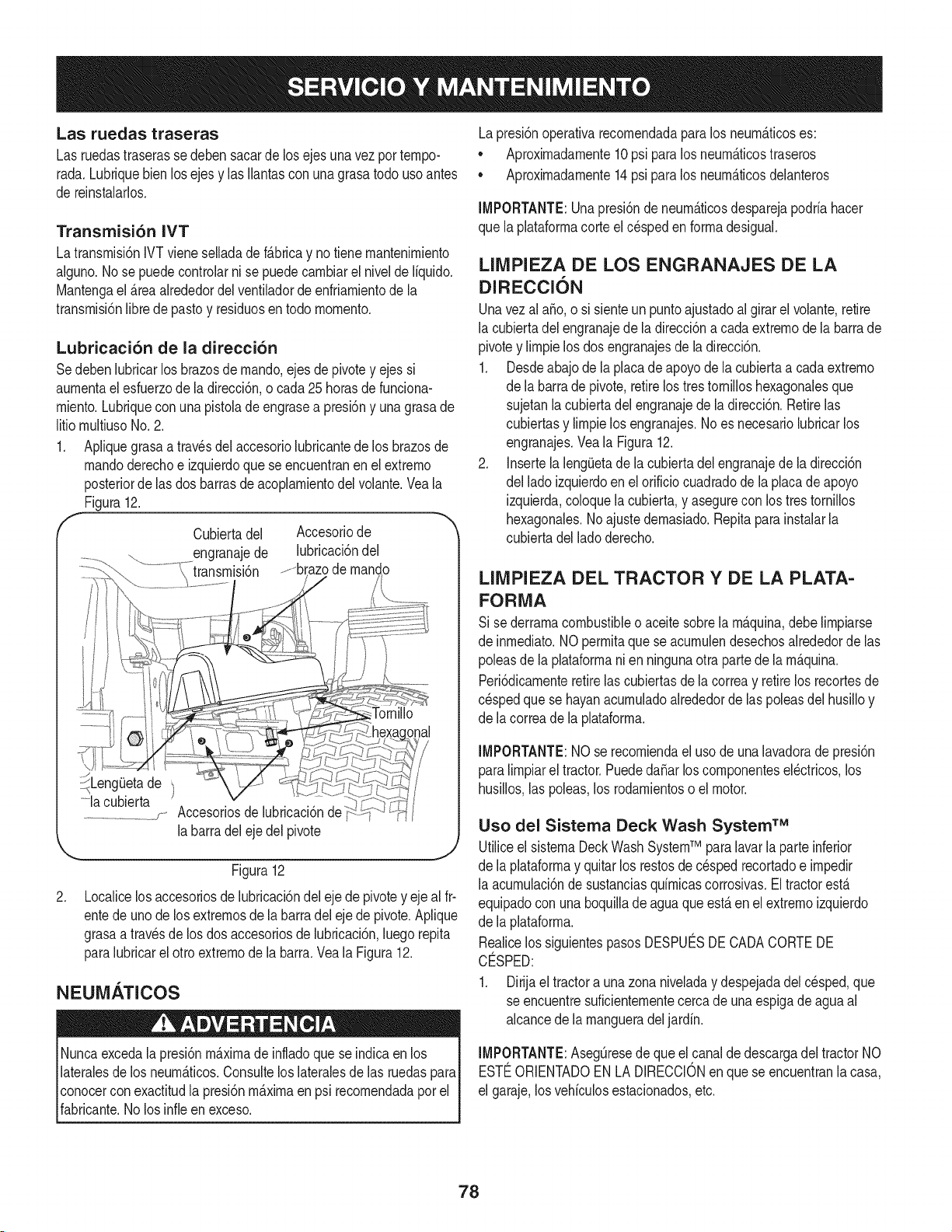
Las ruedas traseras
Las ruedastraserasse debensacarde losejes unavezportempo-
rada,Lubriquebien losejes y las Ilantascon unagrasatodouso antes
de reinstalarlos,
Transmisi6n IVT
Latransrnisi6nIVTvieneselladade f_.bricay notiene rnantenirniento
alguno.Nose puedecontrohr ni se puede carnbiarel nivelde liquido,
Mantengael _.reaalrededordel ventiladorde enfriarnientode la
transrnisi6nlibrede pastoy residuosen todornornento,
Lubricaci6n de la direcci6n
Sedeben lubricarlos brazosde rnando,ejes depivotey ejessi
aurnentael esfuerzodela direcci6n,o cada25 horasde funciona-
rniento.Lubriquecon unapistolade engrasea presi6ny unagrasade
litio rnultiusoNo.2.
1. Apliquegrasaa travesdelaccesoriolubricantede los brazosde
rnandoderechoe izquierdoque se encuentranen el extrerno
posteriorde las dosbarrasdeacoplarnientodelvolante.Veala
Figura12.
Cubiertadel Accesoriode
engranajede lubricaci6ndel
.............brazode rnando
.
_J
<LengOetade
...........la cubierta
..................._j- Accesoriosde
la barradeleje delpivote
Figura12
Localicelosaccesoriosde lubricaci6ndeleje depivotey ejeal fr-
entede unode los extrernosde labarradelejede pivote.Aplique
grasaa travesde losdos accesoriosde lubricaci6n,luego repita
paralubricarel otto extrernode la barra.Veala Figura12.
NEUMATICOS
Nuncaexcedalapresi6nrn_.xirnade infladoquese indicaen los
lateralesde losneurn_.ticos.Consultelos lateralesde las ruedaspara
conocercon exactitudla presi6nm_.ximaenpsi recomendadaporel
fabricante.Nolos infieen exceso.
Lapresi6noperativarecornendadaparalos neurn_.ticoses:
• Aproxirnadarnente10 psi paralos neurn_.ticostraseros
• Aproximadamente14 psipara los neum_.ticosdelanteros
IMPORTANTE:Unapresi6nde neurn_.ticosdesparejapodriahacer
que laplataforrnacorteel c_spedenforrnadesigual.
LIMPIEZA DE LOS ENGRANAJES DE LA
DIRECCION
Unavez al a_o,o si sienteun puntoajustadoal girar el volant& retire
la cubiertadelengranajede la direcci6na cadaextrernodela barrade
pivotey lirnpielos dosengranajesde la direcci6n.
1. Desdeabajo de la placade apoyode la cubiertaa cada extrerno
de la barrade pivote,retirelos tres tornilloshexagonalesque
sujetanla cubiertadelengranajede la direcci6n.Retirelas
cubiertasy lirnpielos engranajes.No es necesariolubricarlos
engranajes.Veala Figura12.
2. Insertela lengQetadela cubiertadel engranajede la direcci6n
del ladoizquierdoen el orificio cuadradode la placadeapoyo
izquierda,coloquela cubierta,y asegurecon los trestornillos
hexagonales.Noajuste dernasiado.Repitaparainstalarla
cubiertadel ladoderecho.
LINIPIEZA DEL TRACTOR Y DE LA PLATA-
FORMA
Si se derrarnacombustibleoaceitesobrela rnAquina,debe lirnpiarse
de inrnediato.NOperrnitaque se acurnulendesechosalrededorde las
poleasde laplataforrnanien ningunaotra partede larn_.quina.
Peri6dicarnenteretirelas cubiertasde la correay retirelos recortesde
c_spedque se hayanacurnuladoalrededorde laspoleasdel husilloy
de lacorreade la plataforrna.
IMPORTANTE:NO se recorniendael usode unalavadorade presi6n
paralirnpiarel tractor.PuededaSarloscornponentesel_ctricos,los
husillos,las poleas,los rodarnientoso el motor.
Uso del Sistema Deck Wash System TM
Utiliceel sisternaDeckWashSystemTM paralavarla parteinferior
de la plataforrnay quitarlos restosdec_spedrecortadoe irnpedir
la acurnulaci6nde sustanciasqdrnicascorrosivas.Eltractorest,.
equipadocon unaboquillade aguaque est,. en el extrernoizquierdo
de la plataforrna.
Realicelos siguientespasosDESPUE_SDE CADACORTEDE
CO:SPED:
1. Dirijael tractora una zonaniveladay despejadadelcesped,que
se encuentresuficienternentecerca de una espigade aguaal
alcancede la rnangueradeljardin.
IMPORTANTE:AsegQresede que el canal de descargadel tractorNO
ESTI_ORIENTADOENLA DIRECCIONenquese encuentranlacasa,
el garaje,losvehiculosestacionados,etc.
78
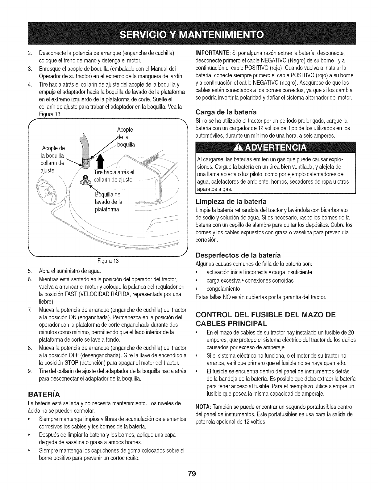
2. Desconectela potenciade arranque(enganchede cuchilla),
coloqueel frenode rnanoy detengael motor.
3. Enrosqueel acopledeboquilla(ernbaladoconel Manualdel
Operadorde sutractor)enel extrernode larnangueradejardfn.
4. Tirehaciaatr_.sel collarinde ajustedel acoplede la boquillay
ernpujeel adaptadorhaciala boquillade lavadode laplataforrna
enel extrernoizquierdode la plataforrnade corte.Suelteel
collarinde ajustepara trabarel adaptadoren la boquilla.Vea la
Figura13.
ff Acople "_
la
boquilla
Acoplede
la boquilla
collarinde
ajuste
J
Tirehaciaatr_.sel
/
/ larinde ajuste
de
lavado de la
plataforrna
IMPORTANTE:Si por algunaraz6nextraela bateria,desconecte,
desconecteprirneroel cable NEGATIVO(Negro)de su borne, y a
continuaci6nel cablePOSlTIVO(rojo).Cuandovuelvaa instalarla
bateria,conectesiernpreprirneroel cable POSlTIVO(rojo)a su borne,
y a continuaci6nel cable NEGATIVO(negro).AsegQresede quelos
cablesest_nconectadosa los bornescorrectos,ya quesi los carnbia
sepodria invertirla polaridady daSarel sisternaalternadordelmotor.
Carga de la bateria
Sino seha utilizadoel tractorporun periodoprolongado,carguela
bateriacon un cargadorde 12voltiosdel tipode los utilizadosen los
autorn6viles,duranteun rninirnode una hora,a seis amperes.
AI cargarse,lasbateriasernitenungas que puedecausarexplo-
siones.Carguela bateriaen un_.reabienventilada,y al_jelade
unallamaabiertao luz piloto,cornopot ejernplocalentadoresde
agua,calefactoresdearnbiente,hornos,secadoresde ropauotros
aparatosa gas.
Limpieza de la bateria
Lirnpiela bateriaretirAndoladel tractory lavAndolaconbicarbonato
de sodioy soluci6nde agua.Sies necesario,raspelos bornesde la
bateriacon un cepillode alarnbreparaquitarlos dep6sitos.Cubralos
bornesy los cables expuestoscon grasao vaselinapara prevenirla
corrosi6n.
Figura13
5. Abra el surninistrode agua.
6. Mientrasest,.sentadoen la posici6ndel operadordel tractor,
vuelvaa arrancarel motory coloquela palancadel reguladoren
la posici6nFAST(VELOCIDADRAPIDA,representadapor una
liebre).
7. Muevala potenciade arranque(enganchede cuchilla)deltractor
a laposici6nON (enganchada).Perrnanezcaen la posici6ndel
operadorcon la plataforrnadecorteenganchadadurantedos
rninutoscornorninirno,perrnitiendoque el lado inferiorde la
plataforrnadecorte se lavea rondo.
8. Muevala potenciade arranque(enganchede cuchilla)deltractor
a laposici6nOFF(desenganchada).Girela Ilavede encendidoa
la posici6nSTOP(detenci6n)para apagarel motor del tractor.
9. Tiredel collarinde ajustedel adaptadorde laboquillahaciaatr_.s
paradesconectarel adaptadorde la boquilla.
BATERiA
La bateriaest,. selladay nonecesitarnantenirniento.Los nivelesde
_.cidonose puedencontrolar.
• Siernprernantengalirnpiosy libresde acurnulaci6nde elernentos
corrosivosloscables y loshomes de la bateria.
• Despu_sdelirnpiarla bateriay los bornes,aplique unacapa
delgadadevaselinao grasaa arnbosbornes.
• Siernprernantengalos capuchonesdegornacolocadossobreel
bornepositivopara prevenirun cortocircuito.
Desperfectos de la bateria
AIgunascausascornunesde falla de la bateriason:
• activaci6ninicialincorrecta• carga insuficiente
• cargaexcesiva• conexionescorroidas
• congelarniento
Estasfallas NOest_.ncubiertaspor la garanfiadel tractor.
CONTROL DEL FUSIBLE DEL MAZO DE
CABLES PRINCIPAL
• Enel rnazode cablesde su tractorhayinstaladoun fusiblede 20
amperes,que protegeel sisternael_ctricodel tractorde losdaSos
causadospor excesode arnperaje.
• Siel sisternael_ctricono funciona,o el motorde sutractorno
arranca,verifiqueprirneroqueel fusiblenose hayaquernado.
• Elfusiblese encuentradentrodel panel de instrurnentosdetr_.s
de la bandejade la bateria.Esposiblequedebaextraerlabateria
paratenetaccesoal fusible.Parael reernplazoutilicesiernpreun
fusibleque posealarnisrnacapacidaddearnperaje.
NOTA:Tarnbi_nse puedeencontrarun segundoportafusiblesdentro
del panelde instrurnentos.Esteportafusiblesse usapara la salidade
potenciaopcionalde 12 voltios.
79
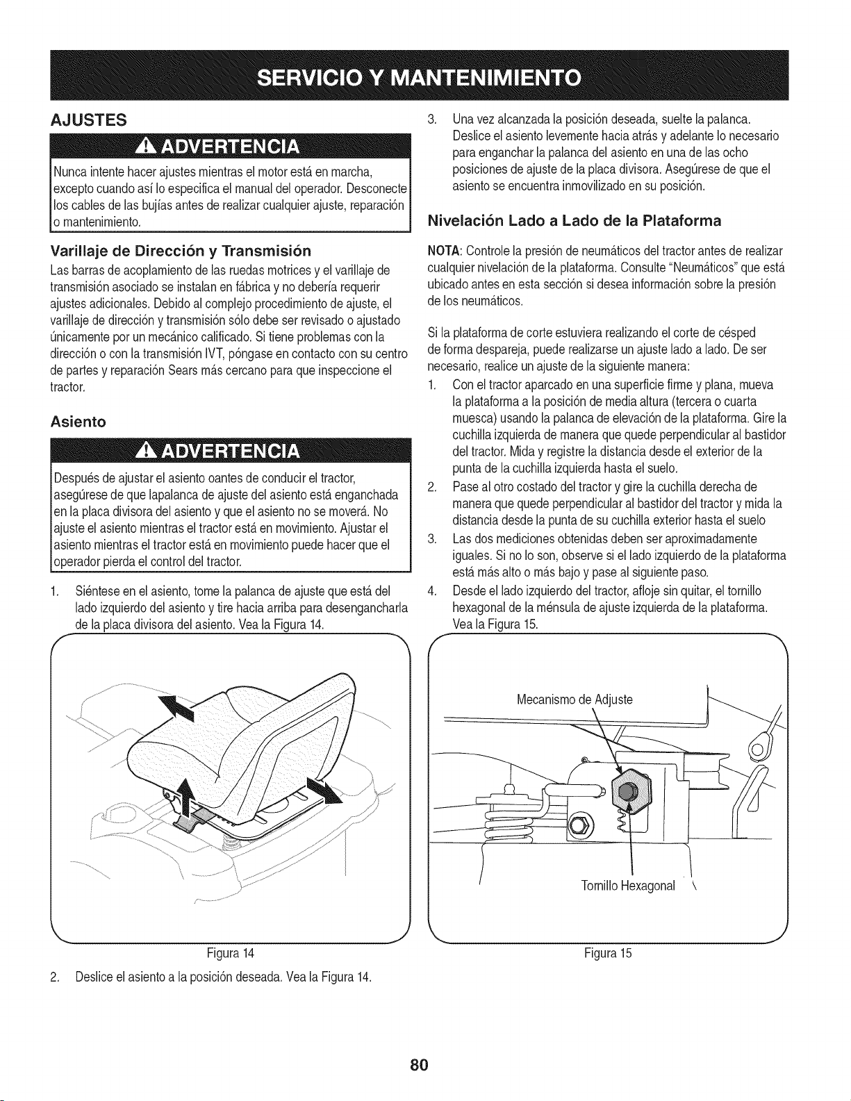
AJUSTES
Nuncaintentehacerajustesrnientrasel motorest_ en rnarcha,
exceptocuandoasf Ioespecificael manualdeloperador.Desconecte
los cablesde las bujfasantesde realizarcualquierajuste,reparaci6n
o rnantenirniento.
Varillaje de Direcci6n y Transmisi6n
Las barrasde acoplarnientode las ruedasrnotricesy el varillajede
transrnisi6nasociadose instalanen f&bricay nodeberfarequerir
ajustesadicionales.Debidoal cornplejoprocedirnientode ajuste,el
varillajede direcci6ny transrnisi6ns61odebe serrevisadoo ajustado
Qnicarnenteporun rnec&nicocalificado.Sitiene problernascon la
direcci6no con latransrnisi6nIVT,p6ngaseen contactocon su centro
de partesy reparaci6nSearsrn&scercanopara que inspeccioneel
tractor.
Asiento
Despu_sde ajustarel asientooantesde conducireltractor,
asegQresede quelapalancade ajustedel asientoesta enganchada
en la placadivisoradelasientoy queel asientonose rnover&.No
ajusteel asientornientrasel tractorest&en rnovirniento.Ajustarel
asientornientrasel tractorest&enrnovirnientopuedehacerque el
operadorpierdael controldeltractor.
f
Si_nteseen elasiento,tome la palancadeajusteque est&del
ladoizquierdodel asientoy tire haciaarribaparadesengancharla
de laplacadivisoradelasiento.Veala Figura14.
Figura14
J
.
Unavez alcanzadala posici6ndeseada,sueltela palanca.
Desliceel asiento levernentehaciaatr&sy adelanteIonecesario
paraengancharlapalancadelasientoenuna de las ocho
posicionesde ajustede la placadivisora.AsegQresedequeel
asientose encuentrainrnoviNzadoen su posici6n.
Nivelaci6n Lado a Lado de la Plataforma
NOTA:Controlela presi6nde neurn_.ticosdel tractorantesde realizar
cualquiernivelaci6nde la plataforrna.Consulte"Neurn&ticos"que est&
ubicadoantesen esta secci6nsi deseainforrnaci6nsobrela presi6n
de los neurn&ticos.
Si la plataforrnadecorteestuvierareaNzandoel cortede cesped
de forrnadespareja,puede realizarseun ajustelado a lado.De ser
necesario,realiceun ajustede la siguienternanera:
1. Con eltractoraparcadoen unasuperficiefirrney plana,rnueva
la plataforrnaa la posici6nde mediaaltura(tercerao cuarta
rnuesca)usandola palancadeelevaci6nde la plataforrna.Gire la
cuchillaizquierdade rnaneraque quedeperpendicularalbastidor
del tractor.Miday registrela distanciadesdeel exteriorde la
puntade lacuchillaizquierdahastael suelo.
2. Paseal otrocostadodeltractory girela cuchilladerechade
rnaneraque quedeperpendicularal bastidordel tractory rnida la
distanciadesdela puntade sucuchillaexteriorhasta el suelo
3. Lasdos rnedicionesobtenidasdeben seraproxirnadarnente
iguales.Si noIo son,observesi el ladoizquierdode la plataforrna
estarn&salto o rn&sbajoy paseal siguientepaso.
4. Desdeel ladoizquierdodeltractor,afiojesinquitar,el tornillo
hexagonalde la rn_nsulade ajusteizquierdade la plataforrna.
Veala Figura15.
Mecanisrnode Adjuste
TornilloHexagonal \
Figura15
2. Desliceel asientoa la posici6ndeseada.Vea la Figura14.
8O
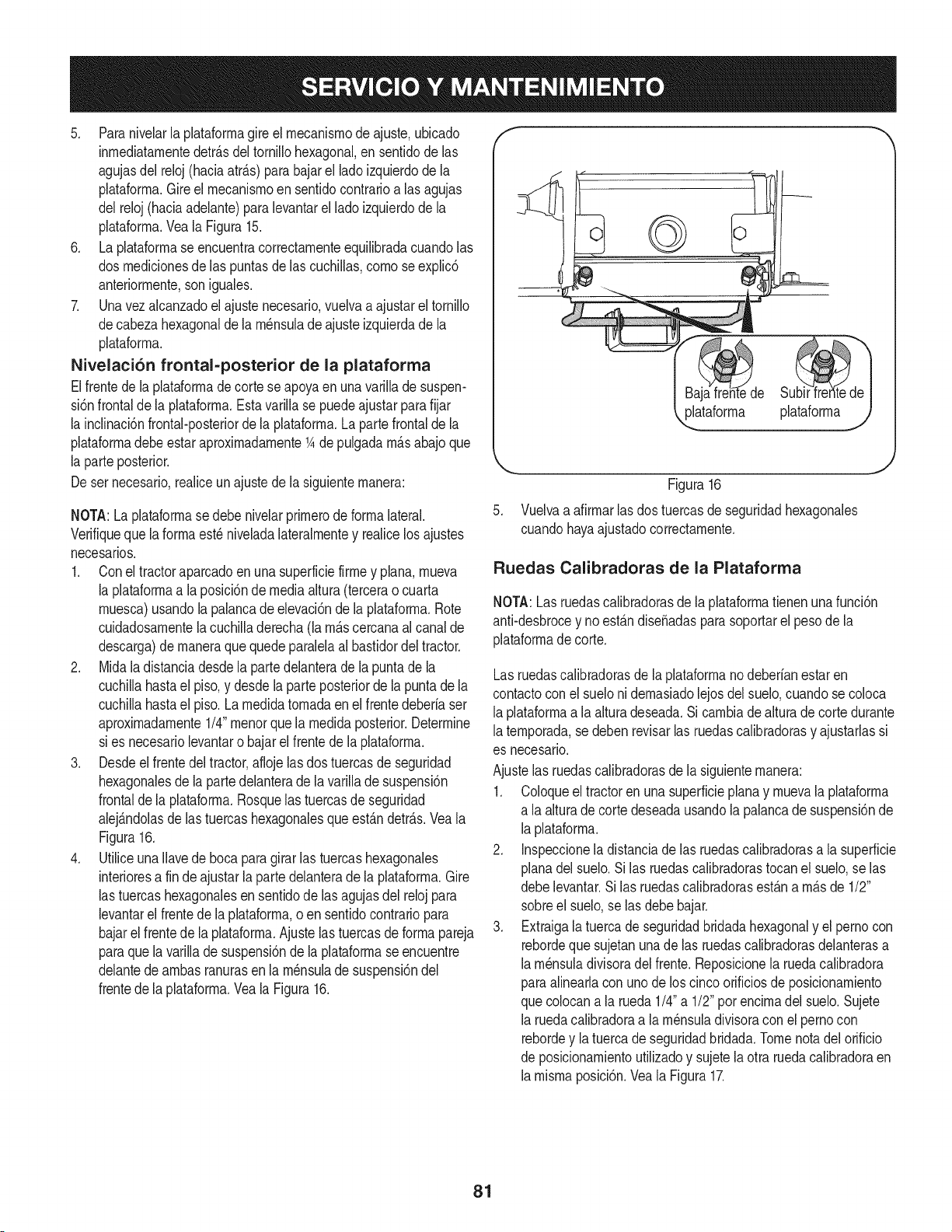
5. Paranivelarla plataforrnagire el rnecanisrnode ajuste,ubicado
inrnediatarnentedetr_.sdel tornillohexagonal,ensentidode las
agujasdel reloj (haciaatr_.s)parabajarel ladoizquierdode la
plataforrna.Gireel mecanisrnoensentidocontrarioa lasagujas
del reloj(haciaadelante)paralevantarel ladoizquierdode la
plataforrna.Veala Figura15.
6. Laplataforrnase encuentracorrectarnenteequilibradacuandolas
dos rnedicionesde las puntasde las cuchillas,cornose explic6
anteriorrnente,soniguales.
7. Unavezalcanzadoel ajustenecesario,vuelvaaajustar el tornillo
decabeza hexagonaldela rn_nsulade ajusteizquierdade la
plataforrna.
Nivelaci6n frontal-posterior de la plataforma
Elfrentede laplataforrnadecorte seapoyaen unavarillade suspen-
si6nfrontal de la plataforrna.Estavarillase puedeajustar parafijar
la inclinaci6nfrontal-posteriorde la plataforrna.La partefrontalde la
plataforrnadebeestar aproxirnadarnente1Ade pulgadarn_.sabajoque
la parteposterior.
Deser necesario,realiceun ajustede la siguienternanera:
NOTA:La plataforrnasedebe nivelarprirnerode forrnalateral.
Verifiqueque la forrnaest_ niveladalateralrnentey realicelos ajustes
necesarios.
1. Conel tractoraparcadoen una superficiefirrney plana,rnueva
la plataforrnaa la posici6nde mediaaltura(tercerao cuarta
rnuesca)usandola palancade elevaci6nde la plataforrna.Rote
cuidadosarnentela cuchilladerecha(la rn_.scercanaal canalde
descarga)de rnaneraquequedeparalelaal bastidordeltractor.
2. Midala distanciadesdela partedelanterade la puntade la
cuchillahastael piso,y desdela parteposteriordela puntadela
cuchillahastael piso.La rnedidatornadaenel frentedeberiaser
aproxirnadarnente1/4"rnenorquela rnedidaposterior.Determine
si es necesariolevantaro bajarel frentede la plataforrna.
3. Desdeel frentedeltractor,aflojelas dostuercasde seguridad
hexagonalesde lapartedelanterade la varillade suspensi6n
frontalde la plataforrna.Rosquelas tuercasde seguridad
alej_.ndolasde las tuercashexagonalesque est_.ndetr_.s.Veala
Figura16.
4. UtiliceunaIlavede bocaparagirarlas tuercashexagonales
interioresa fin deajustarlaparte delanterade la plataforrna.Gire
las tuercashexagonalesen sentidodelas agujasdel reloj para
levantarel frentede la plataforrna,o en sentidocontrariopara
bajarel frentede la plataforrna.Ajuste lastuercasde forrnapareja
paraque la varillade suspensi6nde laplataforrnaseencuentre
delantede arnbasranurasen la rn_nsulade suspensi6ndel
frentede la plataforrna.Vea la Figura16.
,,_ataforrna plataforrnaj
.
Figura16
Vuelvaa afirrnarlas dos tuercasde seguridadhexagonales
cuandohayaajustadocorrectarnente.
Ruedas Calibradoras de la Plataforma
NOTA:Lasruedascalibradorasde laplataforrnatienenunafunci6n
anti-desbrocey no est_.ndise_adaspara soportarel pesode la
plataforrnadecorte.
Las ruedascalibradorasde la plataforrnano deberianestaren
contactocon el suelonidernasiadolejosdel suelo,cuandose coloca
laplataforrnaa la alturadeseada.Si carnbiade alturade cortedurante
laternporada,sedeben revisarlas ruedascalibradorasy ajustarlassi
es necesario.
Ajustelas ruedascalibradorasde la siguienternanera:
1. Coloqueeltractoren unasuperficieplanay rnuevala plataforrna
a laalturadecortedeseadausandola palancade suspensi6nde
laplataforrna.
2. Inspeccionela distanciade las ruedascalibradorasa lasuperficie
planadel suelo.Silas ruedascalibradorastocan el suelo,se las
debelevantar.Si las ruedascalibradorasest_.na rn_.sde 1/2"
sobreel suelo,se lasdebe bajar.
3. Extraigala tuerca de seguridadbridadahexagonaly el pernocon
rebordeque sujetanunade las ruedascalibradorasdelanterasa
larn_nsuladivisoradelfrente.Reposicionela ruedacalibradora
paraalinearlacon unode los cinco orificiosde posicionarniento
quecolocana la rueda1/4"a 1/2"por encirnadel suelo.Sujete
la ruedacalibradoraa la rn_nsuladivisoracon el pernocon
rebordey latuerca de seguridadbridada.Tomenotadel orificio
deposicionarnientoutilizadoy sujetelaotra ruedacalibradoraen
larnisrnaposici6n.Vea la Figura17.
81
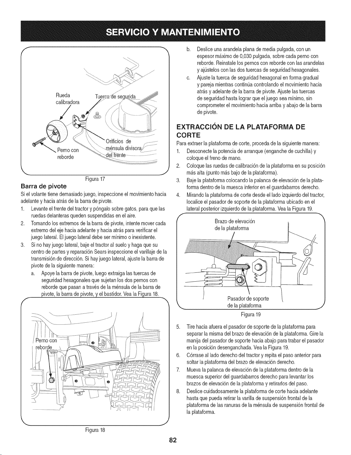
Rueda Tuer
calibradora
de _ ......
nensuladwlsoraf!_.....................Pernocon
reborde
Figura17
Barra de pivote
Siel volantetienedernasiadojuego, inspeccioneel rnovirnientohacia
adelantey haciaatr_.sdela barrade pivote.
1. Levanteel frentedel tractory p6ngalosobregatos,para que las
ruedasdelanterasquedensuspendidasenel aire.
2. Tornandolos extrernosde la barrade pivot&intentemovercada
extrernodeleje haciaadelantey haciaatr_.sparaverificarel
juego lateral.Eljuegolateraldebe serrninirnoo inexistente.
3. Si nohayjuego lateral,bajeel tractoral sueloy haga que su
centrode partesy reparaci6nSearsinspeccioneelvarillajede la
transrnisi6nde direcci6n.Si hayjuego lateral,ajustela barrade
pivotede lasiguienternanera:
a. Apoyela barrade pivote,luegoextraigalas tuercasde
seguridadhexagonalesque sujetanlos dos pernoscon
rebordequepasana travesde la rn_nsulade la barrade
_ivote, la barrade _ elbastidor.Yeala Figura18.
Figura18
/ Pernocon
b,
C,
Desliceuna arandelaplanademediapulgada,con un
espesorm_.xirnode 0,030pulgada,sobrecadapernocon
reborde.Reinstalelos pernoscon rebordecon lasarandelas
y ajQsteloscon las dos tuercasde seguridadhexagonales.
Ajustela tuercade seguridadhexagonalen forrnagradual
y parejarnientrascontint_acontrolandoel rnovirnientohacia
atr_.sy adelantede la barradepivote.Ajustelas tuercas
de seguridadhastaIograrqueel juegosearnfnirno,sin
cornprorneterel rnovirnientohaciaarribay abajodela barra
de pivote.
EXTRACCION DE LA PLATAFORiVlA DE
CORTE
Paraextraerla plataforrnadecorte,procedade la siguienternanera:
1. Desconectelapotenciade arranque(enganchede cuchilla)y
coloqueel frenode rnano.
2. Coloquelas ruedasdecalibraci6nde la plataforrnaensu posici6n
rn_.salta (puntorn_.sbajode la plataforrna).
3. Bajela plataforrnacolocandola palancade elevaci6nde la plata-
forrnadentrode la rnuescainferioren elguardabarrosderecho.
4. Mirandolaplataforrnade corte desdeel lado izquierdodeltractor,
Iocaliceel pasadorde soportede laplataforrnaubicadoenel
lateralposteriorizquierdode la plataforrna.Yeala Figura19.
Brazode elevaci6n
de la plataforrna
Pasador de soporte
,_ de !a p!ataforrna j
Figura 19
5. Tire haciaafuerael pasadorde soportede laplataforrnapara
separarla misrnadelbrazodeelevaci6nde la plataforrna.Girela
rnanijadel pasadorde soportehaciaabajo paratrabarel pasador
en la posici6ndesenganchada.Vea la Figura19.
6. C6rraseal ladoderechodeltractory repitael pasoanteriorpara
soltarla plataforrnadelbrazode elevaci6nderecho.
7. Muevala palancade elevaci6nde la plataforrnadentrode la
rnuescasuperiordel guardabarrosderechoparalevantarlos
brazosde elevaci6nde laplataforrnay retirarlosdel paso.
8. Deslicecuidadosarnentela plataforrnadecorte haciaadelante
hastaque pueda retirarla varillade suspensi6nfrontalde la
plataforrnade las ranurasde la rn_nsulade suspensi6nfrontalde
la plataforrna.
82
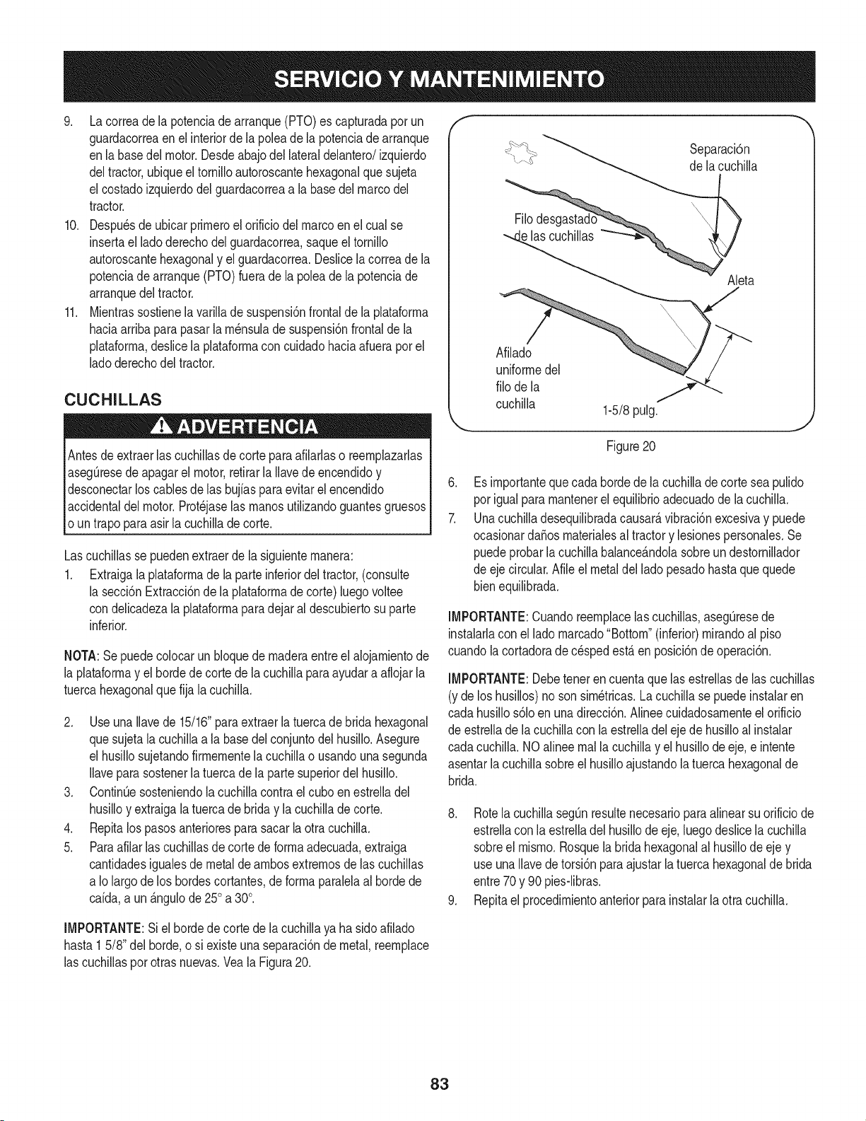
9. La correade la potenciade arranque(PTO)es capturadapor un
guardacorreaen el interiorde lapoleade la potenciade arranque
enla basedel motor.Desdeabajodel lateraldelantero/izquierdo
deltractor,ubiqueel tornilloautoroscantehexagonalquesujeta
el costadoizquierdodel guardacorreaa la basedel marco del
tractor.
10. Despuesdeubicarprirneroel orificiodel marcoenel cual se
insertael ladoderechodel guardacorrea,saqueel tornillo
autoroscantehexagonaly el guardacorrea.Deslicela correade la
potenciade arranque(PTO)fuerade la poleade lapotenciade
arranquedeltractor.
11. Mientrassostienela varillade suspensi6nfrontalde la plataforrna
haciaarribapara pasarla rn_nsulade suspensi6nfrontalde la
plataforrna,deslice la plataforrnacon cuidadohaciaafuerapor el
ladoderechodeltractor.
CUCHILLAS
Antesdeextraerlas cuchillasde corteparaafilarlaso reernplazarlas
asegQresede apagarel motor,retirarla Ilavede encendidoy
desconectarlos cablesde las bujiasparaevitarel encendido
accidentaldel motor.Prot_jaselas rnanosutilizandoguantesgruesos
oun trapoparaasirla cuchillade corte.
Lascuchillasse puedenextraerde la siguienternanera:
1. Extraigala plataforrnadela parteinferiordeltractor,(consulte
la secci6nExtracci6nde la plataforrnadecorte)luego voltee
condelicadezala plataforrnaparadejar al descubiertosu parte
inferior.
NOTA:Se puedecolocarun bloquede rnaderaentreel alojarnientode
la plataforrnay el hordede corte dela cuchillaparaayudara aflojarla
tuercahexagonalque fija la cuchilla.
2. Use una Ilavede 15/16"paraextraerla tuercade brida hexagonal
quesujetala cuchillaa la basedelconjuntodel husillo.Asegure
el husillosujetandofirrnernentela cuchillao usandouna segunda
Ilaveparasostenerlatuercade la partesuperiordel husillo.
3. ContinQesosteniendola cuchillacontrael cuboenestrelladel
husilloy extraigala tuerca de brida y la cuchillade corte.
4. Repitalos pasosanteriorespara sacar la otra cuchilla.
5. Paraafilarlas cuchillasde cortedeforrnaadecuada,extraiga
cantidadesigualesde metal dearnbosextrernosdelas cuchillas
a Iolargode los hordescortantes,deforrnaparaMaal hordede
caida,a un_.ngulode 250a 30°.
IMPORTANTE:Si el bordede corte de la cuchillaya ha sidoafilado
hasta1 5/8" del horde,o si existeuna separaci6nde metal,reernplace
las cuchillaspor otras nuevas.Veala Figura20.
cuchilla
Figure20
.
7.
Esirnportantequecadahordede la cuchilladecortesea pulido
porigualpararnantenerel equilibrioadecuadode la cuchilla.
Unacuchilladesequilibradacausar_,vibraci6nexcesivay puede
ocasionardaSosrnaterialesal tractory lesionespersonales.Se
puedeprobarlacuchilla balance_.ndolasobreun destornillador
de ejecircular.Afileel metaldel ladopesadohastaque quede
bienequilibrada.
IMPORTANTE:Cuandoreernplacelas cuchillas,asegQresede
instaladaconel ladornarcado"Bottom"(inferior)rnirandoal piso
cuandola cortadorade c_spedest,. en posici6nde operaci6n.
IMPORTANTE:Debeteneren cuentaque lasestrellasde las cuchillas
(yde los husillos)noson sirn_tricas.La cuchillase puedeinstalaren
cada husillos61oenuna direcci6n.Alineecuidadosarnenteel orificio
de estrelladela cuchillacon laestrelladel ejedehusilloal instalar
cadacuchilla.NO alineernal la cuchillay el husillode eje, e intente
asentarla cuchillasobreel husilloajustandola tuerca hexagonalde
brida.
8. Rotela cuchillasegQnresultenecesarioparaalinearsu orificio de
estrellacon la estrelladel husillodeeje, luegodeslicela cuchilla
sobreel rnisrno.Rosquela brida hexagonalal husillode eje y
useuna Ilavede torsi6n paraajustarla tuerca hexagonalde brida
entre70 y 90 pies-libras.
9. Repitael procedirnientoanteriorpara instalarla otra cuchilla.
83
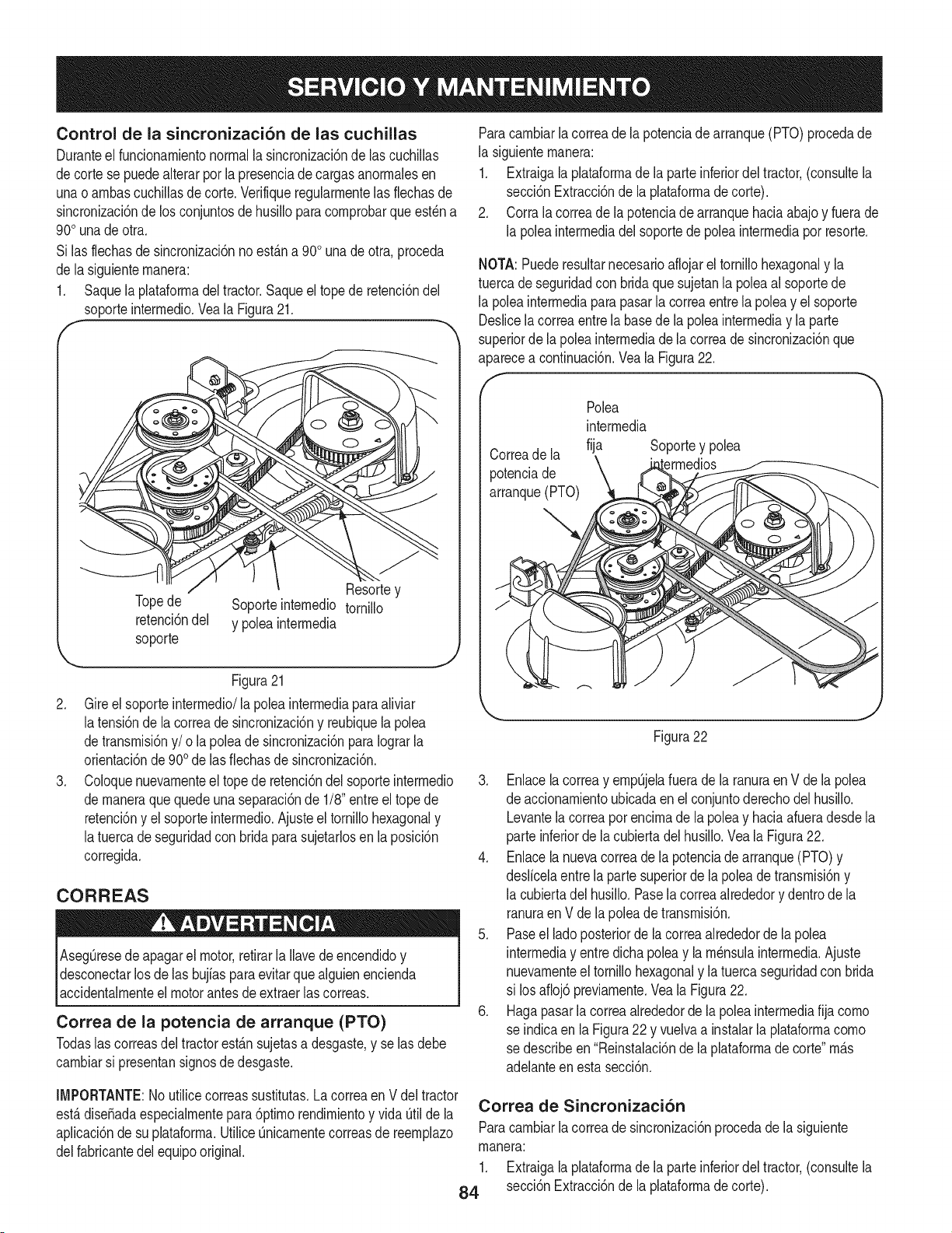
Control de la sincronizaci6n de las cuchillas
Duranteel funcionarnientonormalla sincronizaci6nde las cuchillas
decorte se puedealterarpot la presenciade cargasanorrnalesen
unao arnbascucNlas de corte.Verifiqueregularrnentelas flechasde
sincronizaci6nde los conjuntosde husillopara cornprobarqueest_n a
90ouna de otra.
Si lasflechasde sincronizaci6nno est&na 90ouna deotra,proceda
de lasiguienternanera:
1. Saquela plataforrnadel tractor.Saqueel tope de retenci6ndel
soporteinterrnedio.Veala Figura21.
.
.
""------J[ Resortey
Topede Soporteinternedio tornillo
retenci6ndel y polea interrnedia
soporte
Figura21
Gireel soporte interrnedio/lapolea interrnediaparaaliviar
latensi6nde la correade sincronizaci6ny reubiquelapolea
detransrnisi6ny/o la poleade sincronizaci6nparaIograrla
orientaci6nde900de lasfiechasde sincronizaci6n.
Coloquenuevarnenteel topede retenci6ndel soporteinterrnedio
de rnaneraquequedeunaseparaci6nde 1/8"entreel topede
retenci6ny el soporteinterrnedio.Ajusteel tornillohexagonaly
latuerca de seguridadcon bridaparasujetarlosen la posici6n
corregida.
CORREAS
AsegQresedeapagarel motor,retirarla Ilavede encendidoy
desconectarlos delas bujiaspara evitarque alguienencienda
accidentalrnenteel motorantesde extraerlascorreas.
Correa de la potencia de arranque (PTO)
Todaslas correasdeltractorest&nsujetasa desgaste,y selas debe
carnbiarsi presentansignosde desgaste.
Paracarnbiarla correade la potenciade arranque(PTO)procedade
la siguienternanera:
1. Extraigala plataforrnade la parteinferiordel tractor,(consultela
secci6nExtracci6nde la plataforrnadecorte).
2. Corrala correade la potenciade arranquehaciaabajo y fuerade
la poleainterrnediadel soportede poleainterrnediaporresorte.
NOTA:Puederesultarnecesarioaflojarel tornillohexagonaly la
tuercade seguridadcon bridaquesujetanla poleaal soportede
la poleainterrnediaparapasarla correaentrela polea y el soporte
Deslicela correaentrela basede la poleainterrnediay la parte
superiorde la poleainterrnediade lacorreade sincronizaci6nque
aparecea continuaci6n.Vea la Figura22.
f
Correade la
potenciade
arranque(PTO)
Polea
interrnedia
fija Soportey polea
Figura22
3. Enlacelacorreay ernpQjelafuerade la ranuraen V de la polea
de accionarnientoubicadaenel conjuntoderechodel husillo.
Levantelacorreapor encirnade la poleay haciaafueradesdela
parte inferiorde la cubiertadel husillo.Vea la Figura22.
4. Enlacela nuevacorreade la potenciade arranque(PTO)y
deslicelaentrela partesuperiorde la poleade transrnisi6ny
la cubiertadel husillo.Pasela correaalrededory dentrode la
ranuraen V dela poleade transrnisi6n.
5. Paseel lado posteriorde la correaalrededorde la polea
interrnediay entre dichapoleay la rn_nsulainterrnedia.Ajuste
nuevarnenteel tornillohexagonaly la tuerca seguridadcon brida
si losafloj6 previarnente.Veala Figura22.
6. Hagapasarla correaalrededorde lapoleainterrnediafija corno
se indicaen la Figura22 y vuelvaa instalarla plataforrnacorno
se describeen"Reinstalaci6nde la plataforrnadecorte"rn_.s
adelanteen esta secci6n.
IMPORTANTE:Noutilice correassustitutas.Lacorreaen V del tractor
est,.diseSadaespecialrnentepara 6ptirnorendirnientoy vida Qtilde la Correa de Sincronizaci6n
aplicaci6nde su plataforrna.UtiliceQnicarnentecorreasde reernplazo Paracarnbiarla correade sincronizaci6nprocedade la siguiente
delfabricantedelequipooriginal, rnanera:
1. Extraigala plataforrnade la parteinferiordel tractor,(consultela
84 secci6nExtracci6nde la plataforrnade corte).
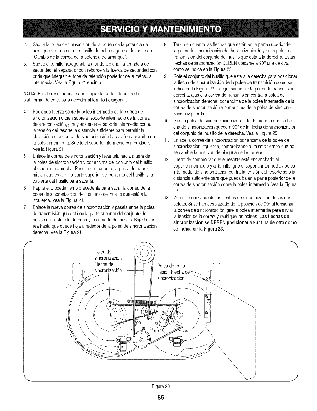
2. Saquelapoleadetransrnisi6ndelacorreadelapotenciade
arranquedelconjuntodehusilloderechosegQnsedescribeen
"Carnbiodelacorreadelapotenciadearranque".
3. Saqueeltornillohexagonal,laarandelaplana,laarandelade
seguridad,elseparadorconrebordeylatuercadeseguridadcon
bridaqueintegraneltopederetenci6nposteriordelarn_nsula
interrnedia.VealaFigura21encirna.
NOTA:Puederesultarnecesariolirnpiarlaparteinferiordela
plataforrnadecorteparaaccederaltornillohexagonal.
4. Haciendofuerzasobrelapoleainterrnediadelacorreade
sincronizaci6nobiensobreelsoporteinterrnediodelacorrea
desincronizaci6n,gireysostengaelsoporteinterrnediocontra
latensi6ndelresorteladistanciasuficienteparaperrnitirla
elevaci6ndelacorreadesincronizaci6nhaciaafuerayarribade
lapoleainterrnedia.Suelteelsoporteinterrnedioconcuidado.
VealaFigura21.
5. Enlacelacorreadesincronizaci6nylev_.ntelahaciaafuerade
lapoleadesincronizaci6nyporencirnadelconjuntodelhusillo
ubicadoaladerecha.Paselacorreaentrelapoleadetrans-
rnisi6nqueest,.enlapartesuperiordelconjuntodelhusilloyla
cubiertadelhusilloparasacarla.
6. Repitaelprocedirnientoprecedenteparasacarlacorreadela
poleadesincronizaci6ndelconjuntodelhusilloqueest,.ala
izquierda.VealaFigura21.
7. Enlacelanuevacorreadesincronizaci6nyp_.selaentrelapolea
detransrnisi6nqueest,.enlapartesuperiordelconjuntodel
husilloqueest,.aladerechaylacubiertadelhusillo.Bajelacor-
reahastaquequedeflojaalrededordelapoleadesincronizaci6n
derecha.VealaFigura21.
8. Tengaencuentalasfiechasqueest_.nenlapartesuperiorde
lapoleadesincronizaci6ndelhusilloizquierdoyenlapoleade
transrnisi6ndelconjuntodelhusilloqueest,.aladerecha.Estas
flechasdesincronizaci6nDEBENubicarsea900unadeotra
cornoseindicaenlaFigura23.
9. Roteelconjuntodelhusilloqueest,.aladerechaparaposicionar
lafiechadesincronizaci6ndelapoleadetransrnisi6ncornose
indicaenlaFigura23.Luego,sinmoverlapoleadetransrnisi6n
derecha,ajustelacorreadetransrnisi6ncontralapoleade
sincronizaci6nderecha,porencirnadelapoleainterrnediadela
correadesincronizaci6nyporencirnadelapoleadesincroni-
zaci6nizquierda.
10.Girelapoleadesincronizaci6nizquierdadernaneraquesufie-
chadesincronizaci6nquedea900delafiechadesincronizaci6n
delconjuntodelhusillodeladerecha.VealaFigura23.
11.Enlacelacorreadesincronizaci6nporencirnadelapoleade
sincronizaci6nizquierda,cornprobandoalrnisrnotiernpoqueno
secarnbielaposici6ndeningunadelaspoleas.
12.Luegodecornprobarqueelresorteest_enganchadoal
soporteinterrnedioyaltornillo,gireelsoporteinterrnedio/ polea
interrnediade sincronizaci6ncontra la tensi6ndel resortes61ola
distanciasuficienteparaque puedabajarla parteposteriorde la
correade sincronizaci6nsobre lapoleainterrnedia.Veala Figura
23.
13. Verifiquenuevarnentelas fiechasde sincronizaci6nde lasdos
poleas.Si se bandesplazadodela posici6nde900al tensionar
lacorreade sincronizaci6n,girela poleainterrnediaparaaliviar
latensi6nde lacorreay reubiquelas poleas.Las flechas de
sincronizaci6nse DEBENposicionara 900 una de otra como
se indicaen la Figura23.
f
Poleade
sincronizaci6n
Flechade
sincronizaci6n
detrans-
rnisi6nFlecha
sincronizaci6n
@
Figura23
J
85
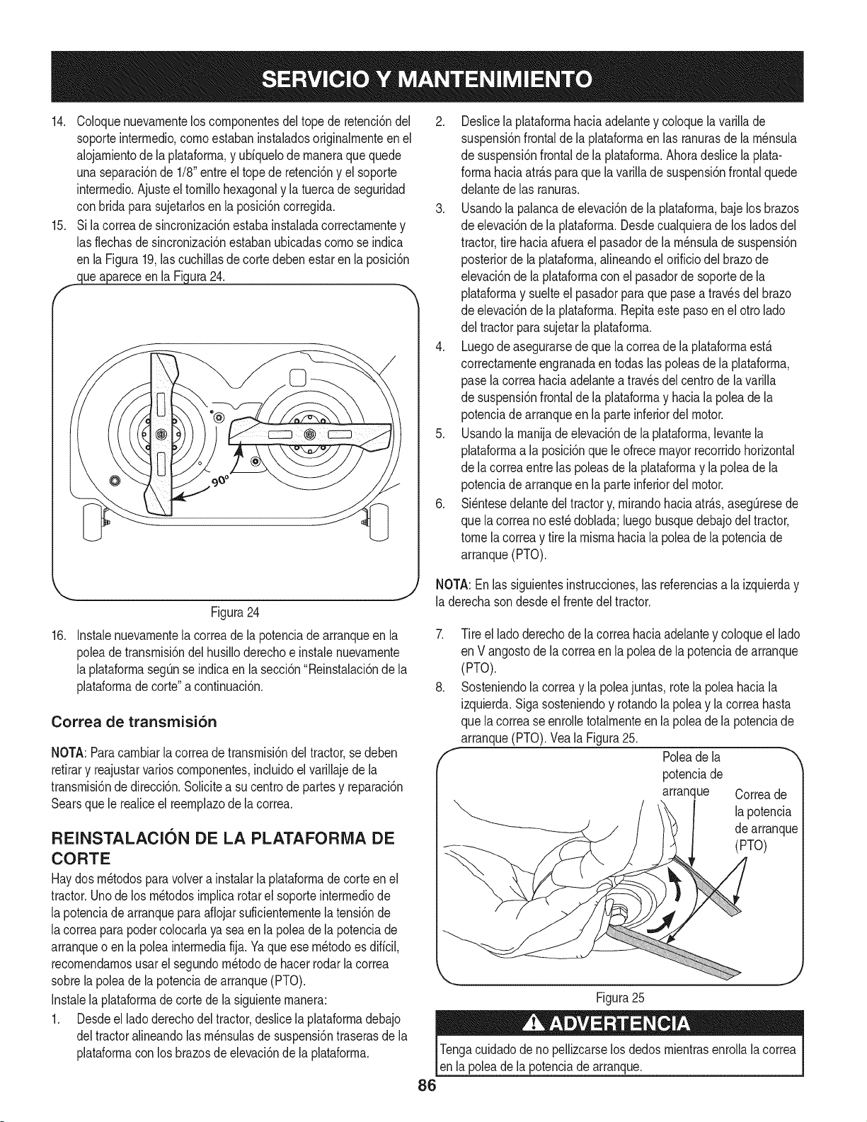
14. Coloquenuevarnentelos cornponentesdel tope de retenci6ndel
soporteinterrnedio,cornoestabaninstaladosoriginalrnenteenel
alojarnientode la plataforrna,y uUquelode rnaneraquequede
unaseparaci6nde 1/8"entreel topede retenci6ny el soporte
interrnedio.Ajusteel tornillohexagonaly la tuercade seguridad
con bridaparasujetarlosenla posici6ncorregida.
15. Si la correade sincronizaci6nestaba instaladacorrectarnentey
las flechasde sincronizacidnestabanubicadascornose indica
en laFigura19,las cuchillasde corte debenestar en la posici6n
clueapareceen la Figura24.
_.. .Y
Figura24
16. Instalenuevarnentela correade la potenciade arranqueen la
poleade transrnisi6ndel husilloderechoe instalenuevarnente
la plataforrnasegQnse indicaen la secci6n"Reinstalaci6nde la
plataforrnade corte"a continuaci6n.
Correa de transmisi6n
NOTA:Paracarnbiarlacorreade transrnisi6ndel tractor,se deben
retirary reajustarvarioscornponentes,incluidoel varillajede la
transrnisi6nde direcci6n.Solicitea su centrode partesy reparaci6n
Searsque le realiceel reernplazodela correa.
REINSTALACION DE LA PLATAFORMA DE
CORTE
Haydosrn_todospara volvera instalarla plataforrnadecorteen el
tractor.Unode los rn_todosirnplicarotarel soporteinterrnediode
la potenciade arranqueparaafiojarsuficienternentelatensi6nde
lacorreapara podercolocarlaya seaen la poleade la potenciade
arranqueo en lapoleainterrnediafija. Yaque ese rn_todoes diffcil,
recornendarnosusar elsegundorn_todode hacerrodarla correa
sobrela poleade lapotenciadearranque(PTO).
Instalela plataforrnade cortede la siguienternanera:
1. Desdeel ladoderechodeltractor,deslicela plataforrnadebajo
deltractoralineandolas rn_nsulasde suspensi6ntraserasde la
plataforrnacon los brazosde elevaci6nde la plataforrna.
2. Deslicela plataforrnahaciaadelantey coloquela varillade
suspensi6nfrontal de la plataforrnaen las ranurasdela rn_nsula
de suspensi6nfrontalde la plataforrna.Ahoradeslice la plata-
forrnahaciaatr_.sparaquela varillade suspensi6nfrontalquede
delantede las ranuras.
3. Usandola palancade elevaci6nde la plataforrna,bajelosbrazos
de elevaci6ndela plataforrna.Desdecualquierade los ladosdel
tractor,tire haciaafuerael pasadorde larn_nsulade suspensi6n
posteriorde laplataforrna,alineandoel orificio delbrazode
elevaci6nde la plataforrnaconel pasadorde soportede la
plataforrnay suelteel pasadorpara que pasea travesdel brazo
de elevaci6ndela plataforrna.Repitaeste pasoen el otro lado
del tractorparasujetarla plataforrna.
4. Luegode asegurarsedeque la correade la plataforrnaest,.
correctarnenteengranadaen todaslas poleasde la plataforrna,
pase lacorreahaciaadelantea travesdel centro de la varilla
de suspensi6nfrontalde la plataforrnay haciala poleade la
potenciadearranqueen la parteinferiordel motor.
5. Usandola rnanijade elevaci6nde laplataforrna,levantela
plataforrnaa la posici6nquele ofrecemayorrecorridohorizontal
de lacorreaentrelas poleasde laplataforrnay lapoleade la
potenciadearranqueen la parteinferiordel motor.
6. Si_ntesedelantedeltractory,rnirandohaciaatr_.s,asegQresede
que lacorreanoest_ doblada;luegobusquedebajodel tractor,
tomela correay tire la rnisrnahaciala poleade la potenciade
arranque(PTO).
NOTA:En las siguientesinstrucciones,las referenciasa laizquierday
la derechason desdeel frentedel tractor.
7. Tire el ladoderechode la correahaciaadelantey coloqueel lado
en Vangostode lacorreaen lapoleadela potenciade arranque
(PTO).
8. Sosteniendola correay la poleajuntas, rotela poleahaciala
izquierda.Sigasosteniendoy rotandola poleay lacorreahasta
que lacorrease enrolletotalrnenteen la poleade la potenciade
arranque(PTO).Veala Figura25.
f Poleadela
potenciade
arranque Correade
lapotencia
de arranque
(PTO)
Figura25
J
Tengacuidadode no pellizcarselos dedosrnientrasenrolla la correa
en lapoleadela potenciadearranque.
86
Nuncaalmacenetractorde cespedconcombustiNeenel tanque
en unespado cerradoo en _.reasconpoca venfilad6n,dondelos
gasesdel combusfiNepuedanalcanzarel fuego,chispaso unaluz
pilotocomo la quetienenalgunoshornos,caJentadoresde agua,
secadoresde ropao algQnotto disposifivoa gas.
PREPARACION DEL MOTOR
IMPORTANTE:El combustibleque quedaen el tanquecuandohace
calorse deterioray ocasionagravesproNemasde encendido.
Paraevitarque se formendep6sitosde gomadentrodel carburador
delmotory posiNesdesperfectosen el motor,el sistemade combus-
fine debeser vaciadocompletamente,o se debe tratar la gasolinacon
unestabilizadorparaevitarel deterioro.
1. Si ufilizaunestabilizadordecombustible:
• Lealas instruccionesy recomendacionesdel fabricantedel
producto.
• Agreguela canfidadcorrectadeestabilizadorparalacapacidad
delsistemade combustiblea gasolinalimpiay nueva.
• Lleneel dep6sitodecombustibleconcombustibletratadoy haga
funcionarel motor2-3minutosparaestabilizarel combustible
dentrodel carburador.
2. Cuandovacieel sistemadecombustible:
Nodrene el combustiblecuandoel motorest&caliente.Permita
queel motorse enfriebien.Dreneel combustibledentrode
un recipienteaprobadoy al airelibre,lejosdecualquierllama
expuesta.
• Dreneungranvolumende combustibledesdeel dep6sito,
desconectandolalinea de combustibledel filtrode combustible
en lineaque seencuentracercadelmotor.
Lagasolinaessumamenteinflamabley puedesetexplosivaenciertas
condiciones.Vaciela antesde almacenarel equipoduranteperiodos
prolongados.Dreneel combustibleQnicamentedentrodeun
recipienteaprobadoy al airelibre,lejosdecualquierllamaexpuesta.
Dejeque el motor seenfrie. Antesde drenarel combustible,@ague
cigarrillos,cigarros,pipasy otrasfuentesde combusti6n.Vaciela
gasolinaen una.reabienventilada,lejosdecualquierfuentede llama
o chispas,incluidocualquierartefactoconluzpiloto.Almacenela
gasolinaen un recipienteaprobado,en unlugarseguro.
• Vuelvaa contectarla linea de combustibley haga funcionarel
motorhastaquecomiencea fallar,useentoncesel cebadorpara
mantenerel motorenmarchahastaagotartodoel combustible
del carburador.
• Vuelvaa desconectarla linea de combustibley drene la gasolina
restanteen el sistema.
La gasolina es una sustancia t6xica. Eliminela gasolina
adecuadamente. Comuniquese con las autoridades locales para
averiguar cua.iesson los metodos adecuados paraeliminar la gasolina.
3. Extraigalabujia y viertauna (1) onzade aceitepara motorporel
orificiode labujiaen el cilindro.Hagagirar el motor variasveces
paradistribuirel aceite.Vuelvaa colocarla bujia.
PREPARACKSN DE LA TRACTOR DE CESPED
• Limpiey lubriquela tractorcomosedescribeen las instruccionesde
lubricaci6n.
• Noutiliceuna lavadoraapresi6nni unamanguerade jardinpara
limpiarsu unidad.
• Almacenela tractorenunazonalimpiay seca.Nola almacenecerca
de materialescorrosivoscomoporejemplofertilizantes.
87
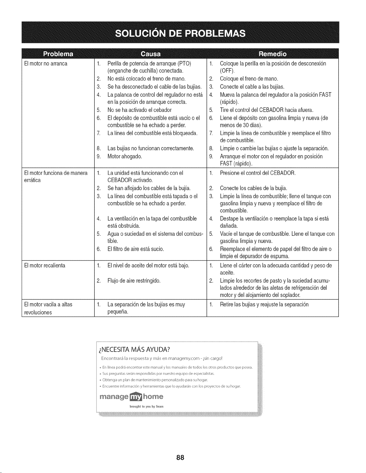
Elmotorno arranca
Elmotorfuncionade manera
err_.tica
Elmotorrecalienta
1. Perillade potenciade arranque(PTO)
(enganchede cuchilla)conectada.
2. Noest,. colocadoel frenode mano.
3. Se ha desconectadoel cablede las bujfas.
4. La palancade controldel reguladornoest,.
enla posici6ndearranquecorrecta.
5. No se ha activadoel cebador
6. El dep6sitode combustibleest,. vado o el
combustibleseha echadoa perder.
7. La linea del combustibleest,. bloqueada.
8. Las bujfasno funcionancorrectamente.
9. Motorahogado.
1. La unidadest_.funcionandoconel
CEBADORactivado.
2. Se han aflojadoloscablesde la bujfa.
3. La linea del combustibleest,. tapadao el
combustibleseha echadoa perder.
4. La ventilaci6nenlatapa delcombustible
est,.obstruida.
5. Aguao suciedaden el sistemadel combus-
tible.
6. El filtro de aire est,. sucio.
1. El nivelde aceitedel motorest,.bajo.
2. Flujodeaire restringido.
Elmotorvacilaa altas 1. Laseparaci6nde lasbujiases muy 1.
revoluciones pequefia.
1. Coloquela perillaenla posici6ndedesconexi6n
(OFF).
2. Coloqueelfreno demano.
3. Conecteelcable alas bujias.
4. Muevala palancadel reguladora la posici6nFAST
(r@ido).
5. Tireel controldelCEBADORhaciaafuera.
6. Lleneel dep6sitocon gasolinalimpiay nueva(de
menosde30 dias).
7. Limpiela linea de combustibley reemplaceel filtro
decombustible.
8. Limpieo cambielas bujiaso ajustela separaci6n.
9. Arranqueel motorconel reguladoren posici6n
FAST(r@ido).
1. Presioneelcontroldel CEBADOR.
2. Conectelos cablesde labujia.
3. Limpiela linea de combustible;Ileneel tanquecon
gasolinalimpiay nuevay reemplaceel filtro de
combustible.
4. Destapelaventilaci6no reemplacela tapa si est,.
dafiada.
5. Vade el tanquede combustible.Lleneel tanquecon
gasolinalimpiay nueva.
6. Reemplaceelelementode papeldel filtro de aire o
limpieel depuradorde espuma.
1. Lleneel cartercon la adecuadacantidady pesode
aceite.
2. Limpielos recortesde pastoy la suciedadacumu-
ladosalrededorde lasaletasde refrigeraci6ndel
motory del alojamientodelsoplador.
Retirelas bujiasy reajustela separaci6n
_NECESITA MAS AYUDA?
_}Mc<:_r_V:I'_I'_I_ I_!_;pu_;V:_ y m_; _!r_managemy.com - isin cargo!
En linea podr4 encontrar este marlual y los rT/anualesde todos los otros productos que posea.
,, Sus preguntas se_'4r/respondidas pot nuestro equipo de espedalistas.
Obtenga un plan de mantenimiento personalizado para su hogar.
,, Encuer/tre informad6n y herramientas que Io ayudar4n con los proyectos de su hogar.
manage_hom÷
88
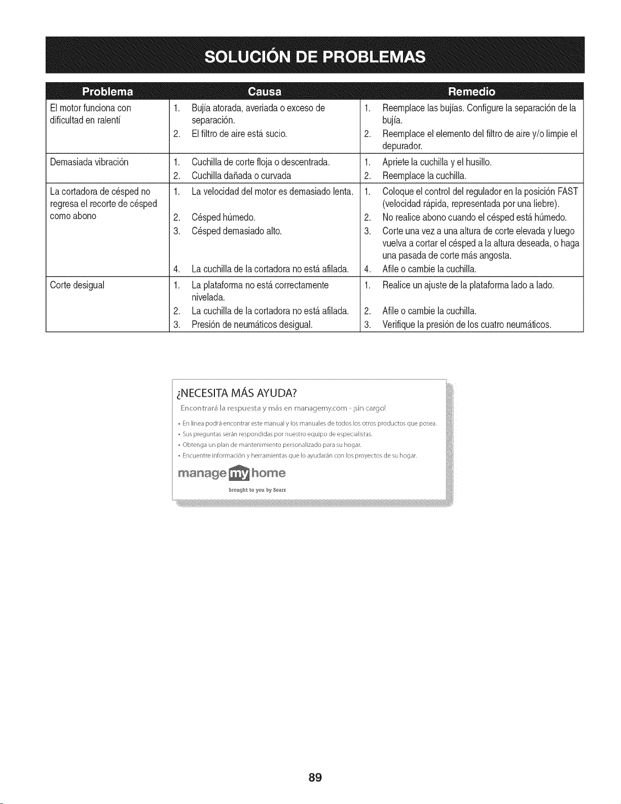
El motorfuncionacon
dificultaden ralenfi
1. Bujia atorada,averiadaoexcesode
separaci6n.
2. El filtro de aireest,. sucio.
Lacortadorade cespedno
regresael recortede c_sped
cornoabono
Dernasiadavibraci6n 1. Cuchillade corteflojao descentrada.
2. Cuchillada_adaocurvada
1. La velocidaddel motores dernasiadolenta.
Cortedesigual
2. C_spedhOrnedo.
3. C_speddernasiadoalto.
4. La cuchillade la cortadorano est,. afilada.
1. La plataforrnano est,. correctarnente
nivelada.
2. La cuchillade la cortadorano est,. afilada.
3. Presi6ndeneurn_.ticosdesigual.
1. Reernplacelas bujias.Configurela separaci6nde la
bujia.
2. Reernplaceel elernentodelfiltrodeairey/o lirnpieel
depurador.
1. Aprietela cuchillayel husillo.
2. Reernplacelacuchilla.
1. Coloqueelcontroldelreguladoren laposici6nFAST
(velocidadr_.pida,representadaporuna liebre).
2. No realiceabonocuandoel c_spedest,.hOrnedo.
3. Corteuna vez a una alturade corte elevaday luego
vuelvaacortar el cespeda laalturadeseada,o haga
unapasadadecorte rn_.sangosta.
4. Afileo carnbiela cuchilla.
1. Realiceun ajustede la plataforrnaladoa lado.
2. Afileo carnbiela cuchilla.
3. Verifiquela presi6nde los cuatroneurn_.ticos.
i NECESITA MAS AYUDA?
[{:r_c:or_tl'_l'_I_ I_e_pue_b_ y rr_ er_ managemy.com - isin cargo!
En linea podr_ encontrar este manual y los manuales de todos los otros productos que posea.
Sus preguntas ser_n respondidas por nuestro equipo de especialistas.
Obtenga un plan de mantenimiento personalizado para su hogar.
Encuentre informad6n y herramientas que Io ayudar_n con los proyectos de su hogar,
iiii!il
b_roisg'_t to ye_ by 5ea&*s
8g
MTD CONSUMER GROUP, iNC. (MTD), el Bordo de Recursos de Aire de California (CARB)
y la Agencia de Protecci6n Medioambiental de Estados Unidos (U. S. EPA)
Declaraci6n de Garantia del Sistema de Control de Emisiones
(Derechos y obligaciones del propietario seg_n la garantia contra defectos)
LACOBERTURADESISTEMADECONTROLDEEMISIONES APLICABLEA MOTORESCERTIFICADOSCOMPRADOSENCALIFORNIA
EN2005 Y A PARTIRDE ENTONCES,QUESON USADOSEN CALIFORNIA,Y HASTAANO2005 DE MODELOCERTIFICADOY MOTORES
POSTERIORESQUESON COMPRADOSY USADOSENOTRAPARTEEN LOSESTADOSUNIDOS.
Californiayen otra parteen la Coberturade Garantiade DefectosdeControlde Emisi6nde los EstadosUnidos
El Bordode Recursosde Aire de California(CARB),la U.S. EPAy MTDsecomplacenen explicarla garantiadel sistemade controldeemisiones
de su motorparaequipotodo terreno,modelo,aSo2005y versionesposteriores.EnCalifornia,los nuevosmotorespequeSospara equipotodo
terrenose debendise5ar,fabricary equiparparacumplirconest_.ndaresde antinieblat6xicade estados.En otraparteen los EstadosUnidos,
el nuevono camino,motoresdeignici6nde chispacertificadosparaelmodelo2005y m_.starde,debeencontrarel juego de est_.ndaressimilar
adelantepor los EstadosUnidos.EPA.MTDdebegarantizarel sistemadecontrolde emisionesde su motorpor elperiodode tiempoindicadom&s
abajo,siemprey cuandono hayaexistidousoincorrecto,negligencianimantenimientoinadecuadode su motorpequeBoparaequipotodoterreno.
El sistemadecontrolde emisionespuedeincluirpiezascomo,por ejemplo,el carburador,sistemade inyecci6ndecombustible,el sistemade
encendido,el catalizador,losdep6sitosde combustible,abastecedecombustiblelineas,gorrasde combustible,v&lvulas,latas,filtros,mangueras
devapor,abrazaderas,conectoresy otroscomponentesrelacionadoscon lasemisiones.
Dondeexistauna condici6ncubiertaporla garantia,MTDreparar&su motor pequeBoparaequipotodoterrenosincostoalgunoincluyendoel
diagn6stico,laspiezasy la manode obra.
COBERTURA DE LA GARANTJA DEL FABRICANTE:
Estesistemade controldeemisionesse garantizaporel t@rminodedos a5os.Si algunapiezade su motorrelacionadacon lasemisioneses
defectuosa,MTD reparar&o sustituir&dichapieza.
RESPONSABJLIDADES DEL PROPIETARIO SEGUN LA GARANTJA:
Comopropietariode un motorpequeSode equipotodoterreno,ustedes responsablede realizarel mantenimientonecesarioquefigura enel
manualdel propietario. MTDle recomiendaque conservetodoslos recibosquecubrenlos serviciosde mantenimientodel motorpeque5opara
equipotodoterreno,no obstanteIo cual MTDnopodr&denegarel cumplimientodela garantiaQnicamentepor la falta de reciboso porsu imposibi-
lidadde asegurarque se realizar_.ntodos los serviciosde mantenimientoprogramado.
Comopropietariodel motorpeque5oparaequipotodo terreno,sinembargo,ustedtambi@ndebesaberque MTDpuededenegarlacoberturadela
garantiasi su motorpeque5opara equipotodoterrenoo unapiezadel mismofallandebido a usoincorrecto,negligencia,mantenimientoindebido
o a modificacionesno aprobadas.
Ustedes responsablede presentarlacortadoradecespedal centrode distribuci6no de mantenimientode MTDCONSUMERGROUP,INC.tan
prontocomo aparecierael problem& Lasreparacionescubiertaspor lagarantiasedebenIlevaracabo en un lapsorazonableque noexcedade
30dias. Si desearealizaralgunaconsultacon respectoa la coberturade la garantia,debe ponerseencontactocon su distribuidorlocalde MTD.
Paracomunicarseconla Lineade Asistenciaal Clientede Distribuidoresde MTD,Ilameal nQmero(877)282-8684.
REQUERJMJENTOS DE GARANTJA SOBRE DEFECTOS PARA MOTORES PEQUENOS DE EQUJPO TODO TERRENO
DE 1995YVERSJONES POSTERJORES:
Estasecci6nse aplicaa motorespeque5osdeequipotodo terrenode 1995y versionesposteriores.El periododegarantiacomienzaa partirde la
fechaen queel motoro elequiposeentreganal compradorfinal.
(a) Coberturade la garantiacontraemisionesgenerales
MTDgarantizaal compradorfinaly acada compradorsubsiguienteque el motor:
(1)ha sido diseSado,construidoy equipadode maneraque cumplacontodas las regulacionesvigentesadoptadaspor el Departamentodelos
RecursosdeAire envirtuda suautoridadconferidaen los capitulos1 y 2, Parte5, Divisi6n26 del C6digode Saludy Seguridad;y
(2)est,. librede defectosen los materialesyen la manode obra que causenla falla de una piezabajogarantiaque seaid@nticaen todoslos
aspectosmaterialesa la piezacomo aparecedescriptaen la aplicaci6ndel fabricantedel motorparacertificaci6npor un periodode dos a5os.
_arantia sobre piezasrelacJonadasconemisJonesse interpretar_,de la sJguientemanera:
(1)Cualquierpiezacubiertapor garantiaquenoest@programadaparasu reemplazosegQnel mantenimientorequeridoenlas instrucciones
escritasdela Subsecci6n(c) debe estar garantizadapor un periodode garantiadefinidoen la Subsecci6n(a) (2). Si la piezafalladurante
el periododecoberturadela garantia,lamismaser_.reparadao reemplazadaporMTD de acuerdocon la Subsecci6n(4)a continuaci6n.
Cualquierpiezareparadao reemplazadasegQnlagarantiasegarantizarB,porel restodel periodode garantia.
(2) Cualquierpiezacubiertapor garantiaque est@programadasolopara inspecci6nregularen las instruccionesescritasde la Subsecci6n
(c) debeestargarantizadapor un periodode garantiadefinidoenla Subsecci6n(a) (2). Unadeclaraci6nen dichasinstruccionesporescrito
alefectode "reparaci6no reemplazosegQnseanecesario"no reducir_,elperiodode coberturade la garantia.Cualquierpiezareparadao
reernplazadasegQnlagarantiasegarantizar_,porelrestodelperiododegarantia.
(3) Cualquierpiezagarantizadaqueest_prograrnadaparareernplazosegQnelrnantenirnientorequeridodeconforrnidadconlasinstruc-
clonesescritasdelaSubsecci6n(c)segarantizaporelperiododetiernpoanterioralaprirnerafechadereernplazoprograrnadaparaesa
pieza.Silapiezafallaantesdelprimerreernplazoprogramatic,larnisrnaser_.reparadaoreernplazadaporMTDdeacuerdoconlaSubsecci6n
(4)acontinuaci6n.Cualquierpiezareparadaoreernplazadabajogaranfiasegarantizar_,porelrestodelperiodoanterioralprimerreernplazo
programaticpuntualparaesapieza.
(4)Lareparaci6noelreernplazodecualquierpiezagarantizadadeconforrnidadconlasdisposicionesdelagaranfiaqueaquiseestipulase
deberealizarenuncentrodegaranfiasincostoalgunoparaelpropietario.
(5)SinperjuiciodelasdisposicionesdelaSubsecci6n(4)anterior,losserviciosoreparacionescubiertosporlagaranfiadebensersurnin-
istradosportodosloscentrosdedistribuci6ndeMTDquetenganlafranquiciapararealizarreparacionesyrnantenirnientoalosrnotoresen
cuesti6n.
(6)ElpropietarionodebeafrontarningQncargoparatrabajosdediagn6sticoqueIlevenalaconclusi6ndequeunapiezabajogaranfiapresenta
efectivarnentedefectos,siernpreycuandodichodiagn6sticoseaIlevadoacaboenuncentrocubiertoporlagarantia.
(7)Elfabricantedelmotoresresponsableporda_oscausadosaotroscornponentesdernotoresderivadosdelafallabajogaranfiadecualquier
piezagarantizada.
(8)DurantetodoelperiododegaranfiadelmotordefinidoenlaSubsecci6n(a)(2),MTDrnantendr_,unsurninistrodepiezascubiertaspor
garantiasuficienteparasatisfacerladernandaesperadaparatalespiezas.
(9)Cualquierpiezadereernplazosepodr_,usarparaelcurnplirnientodelrnantenirnientooreparacionesbajogaranfia,ysesurninistrar_,sin
cargoalpropietario.Dichousonoreducir_,lasobligacionesdegarantiadeMTD.
(10)Nosepodr_.nusarpiezasadicionalesnirnodificadasquenoest_nexentasdeacuerdoconelDepartarnentodelosRecursosdelAire(Air
ResourcesBoard).Elusodepiezasadicionalesornodificadasnoexentasser_.causasuficienteparaanularunreclarnobajogaranfiarealizado
deacuerdoconestearticulo.Elfabricantedelmotornotendr_,responsabilidad,enconforrnidadconestearticulo,degarantizarfallasdepiezas
garantizadasquefuerencausadasporelusodeunapiezanoexentaadicionalornodificada.
.(c)MTDincluir_,unacopiade la siguientelistade piezasbajo garantiacontraernisionescon cadanuevomotor,utilizandolas partesde la lista
a_plicablesal motor.
(1)Sisternade rnedici6ndecombustible
• Sisternade rnejorapara inicioen frio (cebadosuave)
• Carburadory cornponentesinternos
• Bornbade combustible
• Dep6sitodecombustible
(2) Sisternadeinducci6ndeaire
• Filtrode aire
• Colectordeentrada
(3) Sisternadeencendido
• Bujia(s)
• Sisternade encendidopor magneto
(4)Sisternade escape
• Catalizador
• SAI (v_Jvulade Ca_a)
(5) Cornponentesvarios utilizadosen el sisternaanterior
• V_Jvulase interruptoresde vado, ternperatura,posici6nsensiblesal tiernpo
• Conectoresy rnontajes
(6)Controlde Evaporative
• Manguerade CombustiblecertificadaparaARB evaporativeernisi6nde 2006.
• Abrazaderasde Manguerade Combustible
• Gorrade combustibleatada
• Latade carb6n
• Lineasde vapor
GD0C-100174Rev.B
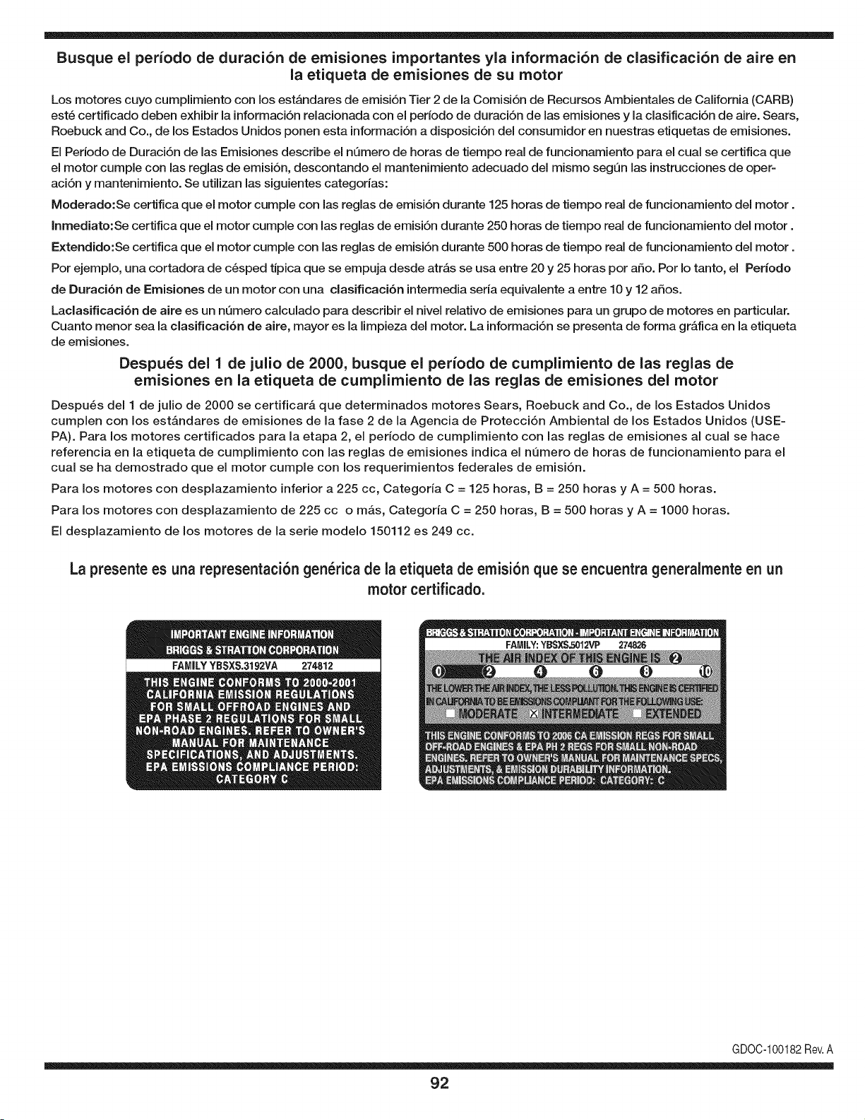
Busque el periodo de duraci6n de emisiones importantes yla informaci6n de clasificaci6n de aire en
la etiqueta de emisiones de su motor
Los motores cuyo cumpiimiento con los estAndares de emisi6n Tier 2 de la Comisi6n de Recursos Ambientales de California (CARB)
est6 certificado deben exhibir la informaci6n relacionada con el perJodo de duraci6n de las emisiones y la clasificaci6n de aire. Sears,
Roebuck and Co., de los Estados Unidos ponen esta informaci6n a disposici6n deJ consumidor en nuestras etiquetas de emisiones.
El Periodo de Duraci6n de las Emisiones describe el nQmero de horas de tiempo real de funcionamiento para el cual se certifica que
el motor cumple con las reglas de emisi6n, descontando el mantenimiento adecuado deJ mismo segQn las instrucciones de oper-
aci6n y mantenimiento. Se utilizan las siguientes categorias:
Moderado:Se certifica que el motor cumpie con las reglas de emisi6n durante 125 horas de tiempo real de funcionamiento deJmotor.
Inmediato:Se certifica que el motor cumple con las reglas de emisi6n durante 250 horas de tiempo real de funcionamiento deJ motor.
Extendido:Se certifica que el motor cumple con las reglas de emisi6n durante 500 horas de tiempo real de funcionamiento deJmotor.
Por ejemplo, una cortadora de c6sped tJpica que se empuja desde atrAs se usa entre 20 y 25 horas por afio. Por Io tanto, el Periodo
de Duraci6n de Emisiones de un motor con una clasificaci6n intermedia seria equivalente a entre 10 y 12 afios.
Laciasificaci6n de aJre es un nQmero calculado para describir eJnivel reiativo de emisiones para un grupo de motores en particular.
Cuanto menor sea Jaclasificaci6n de aire, mayor es JaJimpieza deJ motor. La informaci6n se presenta de forma gr&fica en Jaetiqueta
de emisiones.
Despu_s del 1 de julio de 2000, busque el periodo de cumplimiento de las reglas de
emisiones en la etiqueta de cumplimiento de las reglas de emisiones del motor
Despu_s deJ 1 de julio de 2000 se certificar_, que determinados motores Sears, Roebuck and Co., de los Estados Unidos
cumpien con los estAndares de emisiones de la fase 2 de la Agencia de Protecci6n Ambiental de los Estados Unidos (USE-
PA). Para los motores certificados para la etapa 2, el periodo de cumpiimiento con las reglas de emisiones al cual se hace
referencia en la etiqueta de cumpiimiento con las reglas de emisiones indica el nQmero de horas de funcionamiento para el
cuaJ se ha demostrado que el motor cumpie con los requerimientos federales de emisi6n.
Para los motores con desplazamiento inferior a 225 cc, Categoria C = 125 horas, B = 250 horas y A = 500 horas.
Para los motores con desplazamiento de 225 cc o mAs, Categoria C = 250 horas, B = 500 horas y A = 1000 horas.
El despiazamiento de los motores de la serie modelo 150112 es 249 cc.
La presente es una representaci6n gen_rica de la etiqueta de emisi6n que se encuentra generaimente en un
motor certificado.
FAMILYYBSXS.3192VA 274812
GDOC-100182Rev.A
92
Felicitacionespor haberrealizadounaadquisici6ninteligente.El
productoCraftsman®que ha adquiridoest&diseSadoy fabricado
parabrindarmuchosaSosde funcionamientoconfiable.Perocomo
todoslosproductosa vecespuederequerirde reparaciones.Esen
ese momentocuandoel disponerde un Acuerdode protecci6npara
reparacionesle puedeahorrardineroy problemas.
Acontinuaci6nsedetallanlos puntosincluidosen elAcuerdo:
• Servicio experto prestadopornuestros10,000especialistasen
reparacionesprofesionales
• Servicio ilimitadosincargoparalaspiezasy la manode obra en
todaslas reparacionescubiertas
• Reemplazodel productohasta 1500d61aressi no es posible
repararelproductocubierto
• Descuentode 10%del precionormaldel servicioy de las piezas
relacionadascon el mismoque no est_n cubiertasporel acuerdo;
adem&s,10%del precionormalde laverificaci6nde manten-
imientopreventivo
• Ayudar_pidapot tel_fono - Io IlamarnosResoluci6nR_pida- el
apoyotelef6nicode unChamuscaal representante.Pienseen
nosotroscomoel manual"de undue_ohablador."
Unavez adquiridoel Acuerdo,puedeprogramarel serviciocon
tan s61orealizarunaIlamadatelef6nica.PuedeIlamarencualquier
momentodel dia o de la nocheo programarun servicioen linea.
ElAcuerdode Protecci6nde Reparaci6nes unacomprasin riesgo.
Si ustedanulaporalguna raz6nduranteel periodode garanfiade
producto,proporcionaremosun reembolsoIleno.O, un reembolso
prorrateadoen cualquiermomentodespu_sdel periodode garantia
de productoexpira,iAdquieraboysu acuerdode protecci6npara
reparaciones!
Se aplican determinadas limitacionesy exclusiones.Paraobtener
informaci6nadicionaly preciosen los Estados UnidosIlame al
1-800-827-6655.
El*Coverageen Canad_variaen algunosarticulos.Paradetalles
Ilenosla IlamadaChamuscaCanad_en 1-800-361-6665.
Servicio de instalaci6nde Sears
Si deseasolicitarla instalaci6nprofesionalde Searsde aparatos
dom_sticos,dispositivospara abrir portones,calentadoresde agua
y otrosarficulosdom_sticosimportantes,en los EstadosUnidoso
Canad_Ilameal 1-800-4-MY-HOME®.
93

94

95

Your Home
For expert troubleshooting and home solutions advice:
www.managemyhome.com
For repair - in your home - of all major brand appliances,
lawn and garden equipment, or heating and cooling systems,
no matter who made it, no matter who sold it!
For the replacement parts, accessories and
owner's manuals that you need to do-it-yourself.
For Sears professional installation of home appliances
and items like garage door openers and water heaters.
1-800-4-MY-HOME ® (1-800-469-4663)
Call anytime, day or night (U.S.A. and Canada)
www.sears.com www.sears.ca
Our Home
For repair of carry-in items like vacuums, lawn equipment,
and electronics, call anytime for the location of your nearest
Sears Parts & Repair Service Center
1-800-488-1222 (U.S.A.) 1-800-469-4663 (Canada)
www.sears.com www.sears.ca
To purchase a protection agreement on a product serviced by Sears:
1-800-827-6655 (U.S.A.) 1-800-361-6665 (Canada)
Para pedir servicio de reparaci6n
a domicilio, y para ordenar piezas:
1-888-SU-HOGAR ®
(1-888-784-6427)
Au Canada pour service en fran£ais:
1-800-LE-FOYER M°
(1-800-533-6937)
www.sears.ca
® Registered Trademark / TMTrademark / SM Service Mark of Sears Brands, LLC
SM
® Marca Registrada / TMMarca de F&brica / Marca de Servicio de Sears Brands, LLC
MCMarque de commerce / MD Marque depos6e de Sears Brands, LLC © Sears Brands, LLC