Loading ...
Loading ...
Loading ...
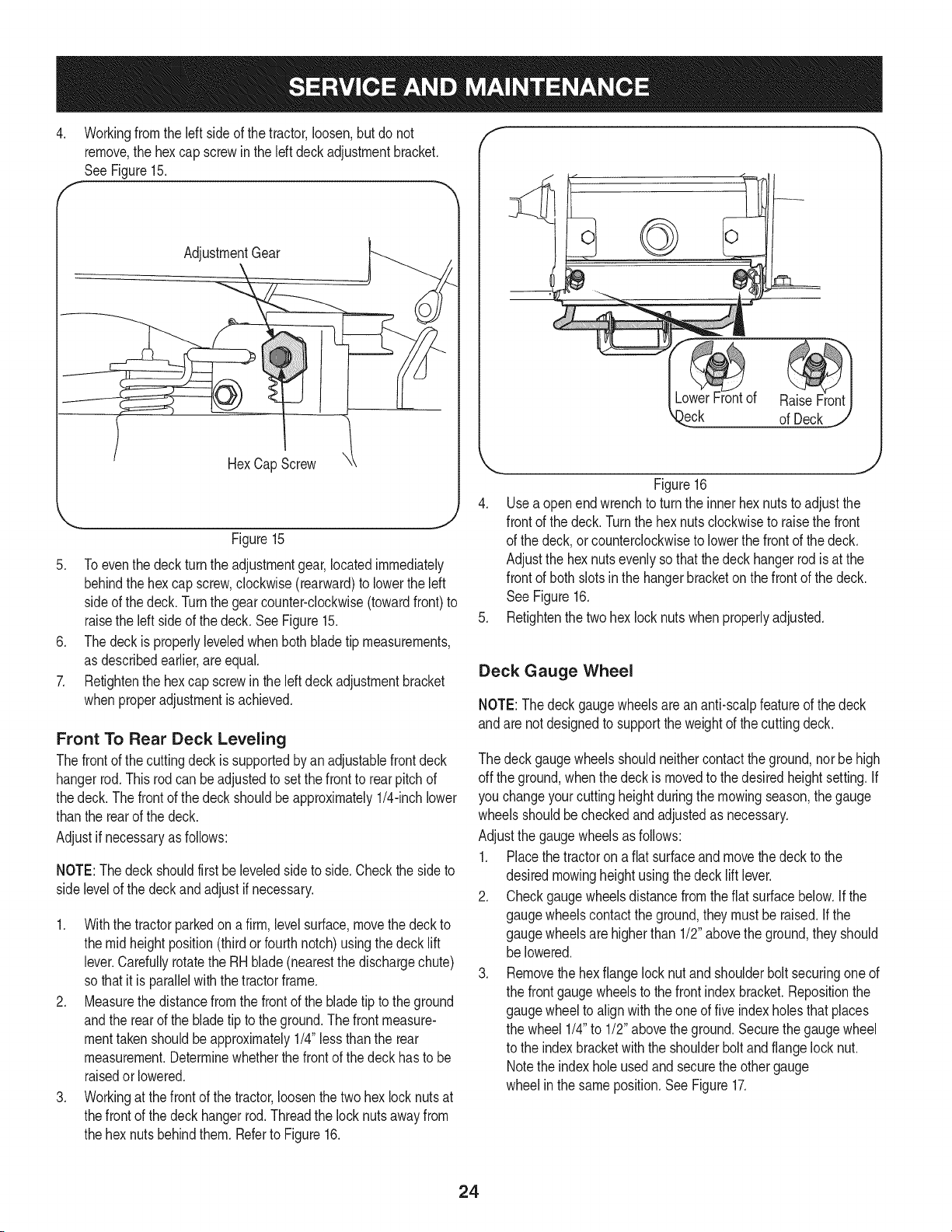
4. Workingfrom the left side of the tractor,loosen,but do not
remove,the hexcap screwin the leftdeckadjustmentbracket.
SeeFigure15.
AdjustmentGear
HexCapScrew
Figure15
5. Toeventhe deckturnthe adjustmentgear,locatedimmediately
behindthe hexcap screw,clockwise(rearward)to lowerthe left
sideof the deck.Turnthe gearcounter-clockwise(towardfront) to
raisethe left sideof the deck.SeeFigure15.
6. Thedeckis properlyleveledwhenbothblade tip measurements,
as describedearlier,are equal.
7. Retightenthe hexcap screwin the left deck adjustmentbracket
whenproperadjustmentis achieved.
Front To Rear Deck Leveling
Thefrontof the cuttingdeckissupportedby an adjustablefrontdeck
hangerrod.This rodcanbeadjustedto setthe frontto rearpitchof
thedeck. Thefrontof the deckshouldbeapproximately1/4-inchlower
thanthe rearof the deck.
Adjustif necessaryas follows:
NOTE:Thedeckshouldfirst beleveledsideto side.Checkthe sideto
side levelof the deck and adjust if necessary.
1. Withthe tractorparkedon a firm,levelsurface,movethe deckto
the midheightposition(thirdor fourthnotch)usingthedeck lift
lever.Carefullyrotatethe RH blade(nearestthe dischargechute)
so thatit is parallelwiththe tractorframe.
2. Measurethe distancefromthe frontof the bladetip to the ground
andthe rearof the bladetip to the ground.The frontmeasure-
menttakenshouldbeapproximately1/4"less thanthe rear
measurement.Determinewhetherthefrontof the deckhasto be
raisedor lowered.
3. Workingat the front of the tractor,loosenthe two hex lock nutsat
thefrontof the deckhangerrod. Threadthe locknutsawayfrom
the hexnutsbehindthem.Referto Figure16.
f
)eck of Deck
Figure16
4. Usea openendwrenchto turnthe innerhexnutsto adjustthe
frontof the deck.Turnthe hexnutsclockwiseto raisethe front
of the deck,or counterclockwiseto lowerthe frontof the deck.
Adjustthe hexnutsevenlysothatthe deckhangerrod isat the
frontof both slotsinthe hangerbracketon the frontof the deck.
See Figure16.
5. Refightenthe twohex locknutswhenproperlyadjusted.
Deck Gauge Wheel
NOTE:The deckgaugewheelsareananti-scalpfeatureof the deck
andare notdesignedto supportthe weightof the cuttingdeck.
The deckgaugewheelsshouldneithercontactthe ground,nor behigh
off the ground,whenthe deck is movedto thedesiredheightsetting.If
you changeyourcuttingheightduringthe mowingseason,the gauge
wheelsshouldbe checkedandadjustedas necessary.
Adjustthe gaugewheelsasfollows:
1. Placethe tractorona fiatsurfaceandmovethe deckto the
desiredmowingheightusingthe decklift lever.
2. Checkgaugewheelsdistancefromthe flat surfacebelow.If the
gaugewheelscontacttheground,theymustbe raised.Ifthe
gaugewheelsare higherthan 1/2"abovethe ground,theyshould
be lowered.
3. Removethe hexflangelocknut andshoulderbolt securingone of
the frontgaugewheelsto the frontindexbracket.Repositionthe
gaugewheelto alignwiththe oneof fiveindexholesthatplaces
the wheel 1/4"to 1/2" abovethe ground.Securethegauge wheel
to the indexbracketwith the shoulderbolt andflangelocknut.
Notethe indexholeusedandsecurethe othergauge
wheelin the sameposition.See Figure17.
24
Loading ...
Loading ...
Loading ...