IDEAL STEEL HYBRID
MODEL 210a
Rev 06/2020
Woodstock Soapstone Company, Inc.
66 Airpark Road, West Lebanon, NH 03784
Toll Free 1-800-866-4344 • www.woodstove.com
Tested To UL 1482-2011 7th Edition
Listed By PFS Corporation
GEAR HEAD STOVES
BY WOODSTOCK SOAPSTONE COMPANY
OWNER’S MANUAL
Tested and Listed by

OUR PROMISE
We are sure you will enjoy your new stove. During the first six months that you own it, test
its performance and experience the comfortable warmth of soapstone. If you are not thor-
oughly delighted with the beauty, quality, and energy efficiency of your stove, you may
return it for a full refund, including the cost of return freight. This is the best consumer pro-
tection plan in the industry.
EPA APPROVAL
This Manual describes the installation and operation of: the Model 210a Ideal Steel Hybrid
Catalytic Wood Stove
The Model 210a Ideal Steel Hybrid Catalytic Wood Stove meets the U.S. Environmental
Protection Agency’s May 2020 cordwood emissions standards. Under specific test conditions,
this stove has been shown to deliver heat at rates ranging from 9,324 to 43263 BTU/hr., and
average emissions of 0.89 grams/hr.
The Steel Hybrid contains a catalytic combustor, which needs periodic inspection and replace-
ment for proper operation. It is against the law to operate this woodstove in a manner incon-
sistent with the operating instructions in this manual, or if the catalytic element is deactivated
or removed.
LISTING TO UL #1482-2011
The Model 210a Ideal Steel Hybrid Catalytic Wood Stove has been tested to UL Standard
#1482 7th edition 2011 for safety, and is listed by PFS Corporation. UL Standard #1482 is the
standard for testing solid fuel heating appliances which is universally recognized by all
national building regulatory agencies (SBCC, BOCA, ICBO) and individual states.
Please Note: Tested and Listed for US installations only
LIMITED WARRANTY
Your Woodstock Soapstone Stove will be carefully inspected before shipment. We will
replace any part which is defective in material or workmanship, free of cost, for a period of
one year from the date of purchase. If a defect is discovered, please contact Woodstock
Soapstone Company, Inc. for instructions regarding return or replacement of the defective
part.
CATALYTIC COMBUSTOR
WARRANTY
The catalytic combustor in your Ideal Steel Hybrid Catalytic Wood Stove is fully warranted
for three years from the date of purchase against any defect in workmanship or materials that
prevent the combustor from functioning when installed and operated properly. The catalytic
combustor is additionally warranted for three years from the date of purchase for any deteri-
oration in the stainless steel substrate material. For instructions regarding return or replace-
ment of the catalytic combustor, please contact:
Woodstock Soapstone Company, Inc.
66 Airpark Road
West Lebanon, NH 03768
Phone: 1-800-866-4344 • Web: www.woodstove.com
GEAR HEAD STOVES
Gear Head Stoves is a division of Woodstock Soapstone Co., which is specifically ‘geared’ to
designing and building high efficiency, low emission, and more affordable wood stoves. The
first Gear Head Stove, The Ideal Steel Hybrid, was the grand prize winner of the 2013 Wood
Stove Design Challenge competition, which judged on efficiency, emissions, affordability,
innovation, and user friendliness. The affordable steel construction, hybrid burn technology,
and Geared 2U custom designs make each stove uniquely affordable and efficient, as well as
uniquely yours.
Tested and Listed by

MODEL 210a
IDEAL STEEL HYBRID CATALYTIC
TABLE OF CONTENTS
WARRANTY INFORMATION/CERTIFICATIONS............ Inside Cover
EPA Certification, UL Listing, Warranty, Catalytic Combustor Warranty
INTRODUCTION
Ideal Steel Hybrid Wood Stove Explained
INSTALLATION......................................... .............. 1-13
Installation, Location, Chimneys, Fireplace Installation, Clearance Table, Wall
Protection, Floor Protection, Setting up Your Stove
OPERATION............................................................14-18
Seasoning Your Stove, Starting a Fire and Establishing Draft, Engaging the
Catalytic Combustor, Reloading & Overnight Burning, Ash Removal, Surface
Thermometer, Overfiring, Daily Use, The Fall-Away Handle, Firewood
CATALYTIC COMBUSTOR........................................ 19-21
How your Combustor Works, Inspection & Cleaning, Replacement, Catalytic
Probe Thermometer, Frequently Asked Questions, Catalytic Combustor
Warranty Information
MAINTENANCE..................................................... 22-23
Stove, Stone & Glass Cleaning, Gasket Replacement, Routine Checks, End-Of-
Season Maintenance, Creosote
TROUBLESHOOTING............................................... 24-25
SAFETY................................................................. 26-27
Overview, Installation, Smoke & The Chimney, Heat, Ash Removal,
Precautions, Emergency Procedures
PARTS LIST & DIAGRAMS......................................... 28-36
MAINTENANCE LOG & NOTE SHEET.............................37
DIMENSION & SPECIFICATIONS............................... Back Cover
Woodstock Soapstone Company, Inc.
66 Airpark Road, West Lebanon, NH 03784
Toll Free 1-800-866-4344 • www.woodstove.com
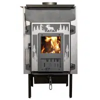
The Ideal Steel Hybrid Combustion System Explained
The Woodstock Soapstone Company’s tradition of build-
ing high quality, dependable wood stoves continues in the
Ideal Steel Hybrid Wood Stove. This new design combines
modern technology to achieve clean and efficient heating
performance with rugged reliability and affordable steel con-
struction.
While the Ideal Steel Hybrid shares some time tested fea-
tures with other members of the Woodstock Soapstone fami-
ly, it also includes some features that are unique. The Ideal
Steel Hybrid has a large glass front that benefits from our
proven air-wash design, but unlike our other wood stoves,
the glass front is also a large loading door. The door swings
open wide for access to a large firebox which can be loaded
front-to-back or side-to-side, depending on the length of your
wood. Innovative andirons protect the glass and can fold out
of the way when the door is opened for loading. The firebox
can be lined with thick soapstone panels or firebrick, and the
exterior is plate steel in order to make the Ideal Steel Hybrid
more affordable.
The Ideal Steel Hybrid has a hybrid combustion system
similar to the one that we pioneered in our Progress Hybrid
wood stove. The combination of the catalytic combustor and
the secondary combustion system gives the operator a wide
range of heat output while maintaining a clean and efficient
burn. In addition to the Hybrid combustion design, the Ideal
Steel Hybrid incorporates new automatic catalyst air to opti-
mize the catalytic combustor’s effec-
tiveness.
Hybrid burn technology
improves efficiency, lowers emis-
sions, and allows for a wider range
of output to meet the heating needs
of the operator. Hybrid stoves from
Woodstock combine the best attrib-
utes of both catalytic combustors and
secondary combustion systems. A
brief description of each is below, fol-
lowed by a more detailed explana-
tion.
Catalytic Combustion:
• Burns woodstove exhaust gases
starting at 500
O
F
• Operates best at low to moderate
burn rates
• Typically yields long duration burns
that are clean and efficient
• Improves stove efficiency by
generating heat from burning
wood smoke
Secondary Combustion:
• Burns woodstove exhaust gases
starting at approximately 1000
O
F
• Operates best at moderate to
high burn rates
• Creates hot firebox for maximum heat output
• Provides a very active fire that is great for viewing
Catalytic combustors are well suited for very long burn
cycles. Catalytic combustors have the ability to reduce or
eliminate woodstove pollution at low stack temperatures.
This means much cleaner, more efficient burns at low firing
rates than is possible without a catalyst. The catalytic reaction
eliminates harmful combustion byproducts and converts
exhaust to water vapor and carbon dioxide. The catalytic
combustor burns exhaust gasses and converts them to heat,
which is captured inside the stove. This extra heat increases
the overall efficiency and output of a catalytic wood stove.
The combustor takes full advantage of the energy in wood
smoke that would otherwise be lost up the chimney as pollu-
tion and wasted energy at low burn rates.
Secondary combustion systems are designed to maximize
efficiency and reduce emissions as well, but they operate dif-
ferently. The secondary combustion system introduces sec-
ondary air in the firebox to ignite the volatile gases produced
by the burning wood. This reaction requires temperatures
over 1000 degrees F to start breaking down the organic com-
pounds in the wood smoke. Secondary combustion systems
work best when the stove has high firebox temperatures and
secondary combustion air introduced into the high tempera-
ture area at the top of the firebox. With secondary combus-
tion the exhaust gases burn at very high temperatures before
leaving the firebox, providing an unusual display of second-
ary flames in the top of the firebox.
In addition to primary and secondary air, the
Ideal Steel Hybrid incorporates a system to intro-
duce air directly to the catalytic combustor as it
heats up. When the catalyst is fully engaged a self
adjusting, bimetallic coil opens a small damper to
allow heated air into the exhaust path just
upstream from the combustor. This dedicated “cat-
alyst air” keeps the combustor active and helps
control primary and secondary burn rates. As the
stove and chimney heat up and draft is increased,
more catalyst air is added automatically. This has
the effect of stabilizing primary and secondary air
and at higher temperatures will actually reduce
primary and secondary air. The catalyst air design
acts similar to a barometric damper.The catalyst air
improves emissions and efficiency at high burn
rates, provides overfire protection, and stabilizes
the burn rate- automatically.
These systems are not mutually exclusive and
have been designed to work together. The Ideal
Steel Hybrid is designed to utilize each system
depending on the conditions present in the fire-
box. This makes operating the Ideal Steel Hybrid
as simple as possible while providing a clean and
efficient burn over a wider range of heat output.
The Ideal Steel Hybrid wood stove. The perfect
combination of affordability, innovative combus-
tion technology, and rugged construction.
INTRODUCTION
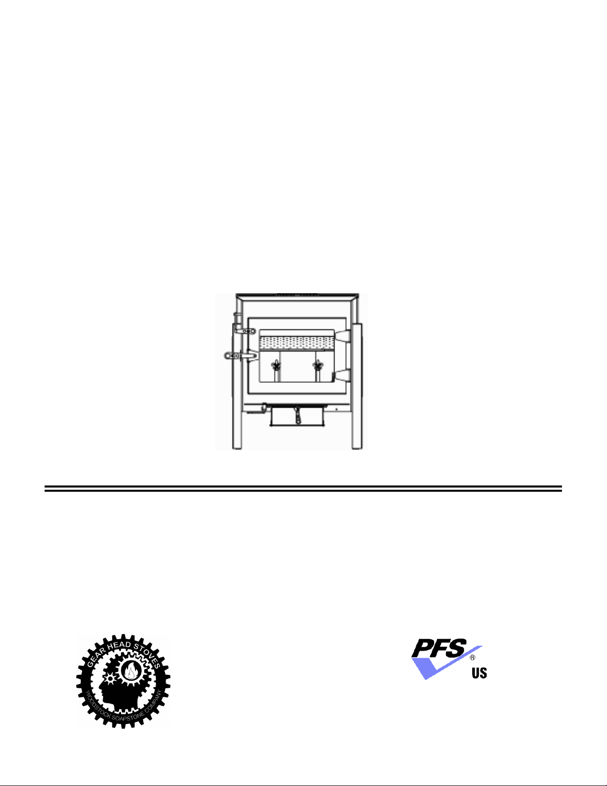
Catalytic bypass open
Three sources of combustion air:
1. primary air,
2. secondary air, and
3. catalyst air
1
2
Catalytic bypass closed
(combustor engaged)
1
2
3
Once the catalytic combustor is engaged,
smoke from the primary & secondary burn
will be directed through the catalytic com-
bustor. The catalyst air will help keep the
combustor operating at peak efficiency.
3
INSTALLATION
LOCATION
A stove which is centrally located will heat the greatest area of your home. Heat should be
able to circulate easily into nearby rooms. Placing your stove near an open stairway or register
in the floor will help transfer heat to other rooms.
Other installation considerations are:
•Clearance to Combustibles
•Adequate Space for Wood Loading and Ash Removal
•Room Traffic Patterns
Most people install their stove in a room they use frequently where they can enjoy the beauty
and comfort of the stove. This also helps in the monitoring and reloading the stove as needed.
A well-planned placement will enhance your enjoyment of your stove and may save installa-
tion costs.
It is not recommended to install a high efficiency stove in an unfinished basement. Heat loss in an unfinished base-
ment is significant, and it is common for high efficiency stove to be overfired in order to compensate for the heat loss
through the unfinished basement walls. For a full article on Basement Installation, visit www.woodstove.com or call 1-800-
866-4344.
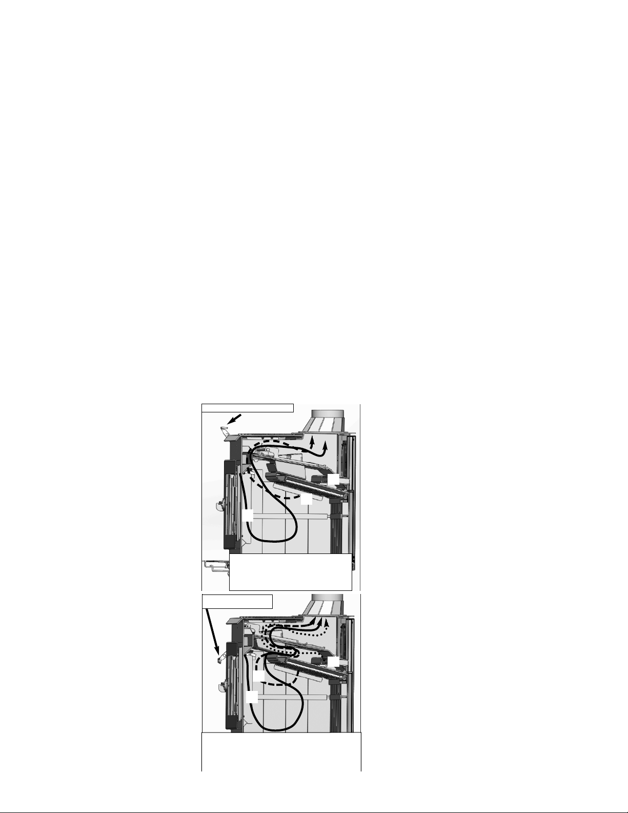
The best location for a chimney and
woodstove is in the center of the
house. The chimney will be
warmer, draft will be better, and
radiant heat will be distributed
more evenly.
ALCOVE INSTALLATIONS
THE MODEL 210 IDEAL STEEL HYBRID WOODSTOVE IS NOT
APPROVED FOR AN
ALCOVE INSTALLATION. AN ALCOVE IS DESCRIBED AS AN AREA LESS THAN 512
CUBIC FEET, WHICH IS EQUIVALENT TO AN 8’X8’X8’ SPACE.
1
For over two centuries, New Englanders have heated their
homes with soapstone stoves. A properly installed and oper-
ated soapstone stove will warm your home and delight your
eye for a lifetime.
Read this entire manual carefully. It explains how to
install your Woodstock Soapstone Ideal Steel Hybrid Wood
Stove safely and how to operate it correctly and efficiently.
The clearances and procedures recommended in this guide
are in compliance with the recommendations of the National
Fire Protection Association (NFPA), the Underwriters
Laboratories (UL), and the U. S. Environmental Protection
Agency (EPA). You may feel some of them are very
stringent, but they should be followed. They were designed
to protect you, your home, and the environment. Improper
installations are a major cause of serious fires. Failure to
follow instructions may result in property damage, bodily
injury, or death.
Before installing a woodstove, check your local building
codes and any requirements established by your insurance
company.
You may need a local building permit to install your stove.
Any changes in your home must comply with building
codes. If the codes have not been fully updated, you may
want to check with the Building Inspection Department or
your local Fire Department. A qualified stove installer
should be aware of any changes and updates to local and
state codes and may be best suited to handle your
installation work.
Many chimney sweeps are qualified installers. If you are
unfamiliar with sweeps or need to locate a certified sweep in
your area, you can check listings at www.csia.org (Chimney
Safety Institute of America). Builders and contractors are
another option. In some cases, homeowners install their own
stoves. Before installing your stove, please review carefully
the stove installation, clearance, and safety information in
this manual. Woodstock Soapstone has NFI (National
Fireplace Institute) certified woodburning specialists on staff
and available to answer any questions you may have about
your installation. If you have questions, please call us toll
free at 1-800-866-4344.
You should notify your insurance company that you are
using a woodstove. Before you light your first fire, have a
local building inspector and your insurance representative
inspect, and approve in writing, your installation.
When this room heater is not properly installed, a house
fire may result. To reduce the risk of fire, follow the
installation instructions. Contact local building or fire
officials about restrictions and installation inspection
requirements in your area.
!
CHIMNEYS
Your chimney is a critical component of your wood heating system. A properly designed and constructed chimney
will help to provide safe and efficient woodstove operation. Hot exhaust rising up through the chimney also pulls com-
bustion air into the stove through the air damper. If a chimney is too short, or the flue too large, the hot exhaust will cool
and slow down. This can lead to poor stove performance, smoke spillage, back puffing, and even creosote build up in
the chimney itself. An excessively tall chimney could lead to a strong draft, which may make the fire difficult to control
with the stove damper. This could result in over firing the stove and lead to damage to the steel components as well as
the catalytic combustor. Whether you are installing a new chimney, or adapting an existing chimney to your woodstove,
close attention to chimney height, flue size, and location should be considered.
Chimney Flue Sizing:
The ideal flue size for the Ideal Steel Hybrid is 6” (28 in
2
), which is the same diameter as
the stove’s flue collar.
If upsizing needs to occur due to an existing chimney the following general rules apply:
1. Interior Chimney (no walls of the chimney exposed to the outside below the roofline): the
inside cross-sectional area of your chimney should be no more than 3x (85 in
2
) the cross-
sectional area of the woodstove flue collar.
2. Exterior Chimney (if there are one or more walls exposed to the outside below the roofline)
- The flue should be no more than 2x (57 in
2
) the cross-sectional area of the flue collar.
Recommendation: The Ideal Steel Hybrid has a 6 inch flue collar, thus an 8 inch x 10 inch
rectangular or 10 inch round flue tile for an inside chimney are the maximum flue sizes we
recommend for this stove. For an outside chimney, an 8 inch x 8 inch square or 8 inch round
would be the largest acceptable. The smallest size we recommend is 6 inches round, as the
flue should not be less than the flue collar size.
Note: For flues that exceed the recommended area, a stainless steel chimney liner is recommended.
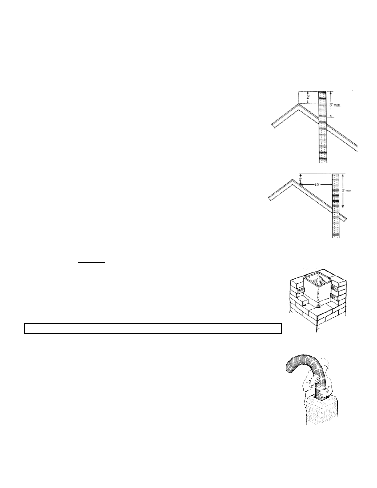
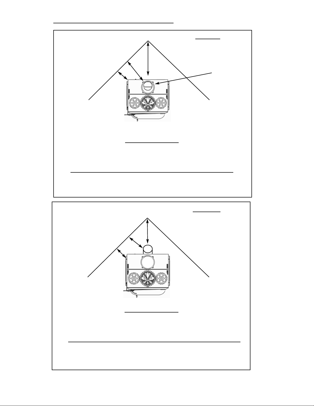
Height Requirements:
The chimney must extend 3 ft. above the point where it passes through the roof and
must
also be 2 ft. higher than any roof surface or obstruction within 10 feet (measured horizontal-
ly) of the chimney. You should check your local building codes for any other requirements.
The recommended minimum
chimney height is 15 feet from the flue collar of the stove to the top of the chimney. This
includes connector pipe and chimney pipe. There may be other factors to conform to code for clear-
ances on the roof, high wind, high altitude, etc., that may make the minimum height undesirable or a
violation of building codes. Woodstock Soapstone does not list a maximum chimney height require-
ment, but it is important to know that a tall chimney (often at or over 30’), can overdraft.
Overdrafting chimneys can cause internal firebox damage. Often the draft can be controlled with
the use of a pipe damper. If you think your chimney may be overdrafting, call us at 1-800-866-4344.
CHIMNEY TYPES
DO NOT CONNECT THIS UNIT TO A CHIMNEY FLUE SERVING ANOTHER APPLIANCE.
There are two acceptable types of chimneys: (1) A chimney complying with the requirements for
Type HT chimneys in the Standard for Chimneys, Factory-Built, Residential Type and Building
Heating Appliance UL 103 OR A code-approved masonry chimney with a flue liner.
Lined Masonry Chimneys:
Always have the chimney inspected prior to your stove installation. If your chimney is not lined
with appropriately sized clay flue tiles, or the clay tiles are old, cracked, damaged or otherwise
compromised, a stainless steel chimney liner or poured liner will be required. Depending on the
condition of your flue or clay tiles, the stainless steel liner may need to be wrapped in a high tem-
perature insulation blanket. A liner may also be recommended if your flue is too large for the draft
to flow properly (please refer to the section on chimney sizing). Our customer service department
can answer any questions regarding the use of a liner and/or insulating blanket. Call 1-800-866-
4344.
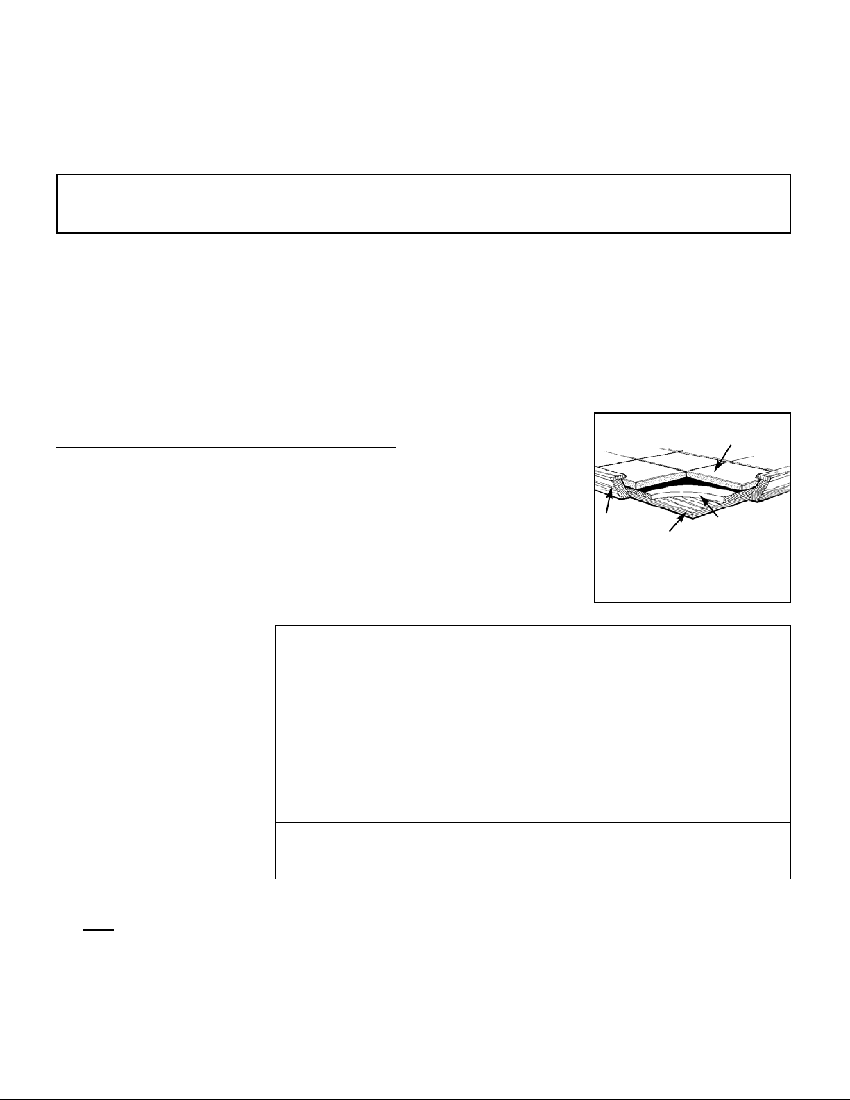
Existing chimneys should be checked twice a year for obstructions, creosote deposits, surface
cracks, chemical deterioration and poor construction. Any damage should be repaired immediately. Two other chimney
related areas that should be checked are chimney penetrations at the floor or ceiling joists, and at the roofline. There
Installing a Stainless Steel
Liner in a Masonry
Chimney
Chimneys must
extend a minimum
of 3’ above roof
penetration...
... and a minimum of 2’
above the highest point
within 10’.
Terra Cotta Tile Lined
Masonry Chimney
2
should be at least 2 inches of clearance between the chimney and floor joists or other com-
bustible materials. Poor flashing between the chimney and the roofline can cause leaks and
deterioration of chimney mortar.
You should make preliminary checks, but if you have any doubts, or are unfamiliar with
chimney construction, cleaning, or maintenance, have a local fire official or certified chimney
professional inspect your chimney. If repairs are required, be sure to use someone who is
knowledgeable in chimney work and familiar with local code requirements.
In addition: All brick or cinder block chimneys should have clean out access with a tightly fit-
ting door. Masonry chimneys should have a wash at the top. All chimneys should have a cap to
keep out rain and snow and to minimize downdrafts caused by wind.
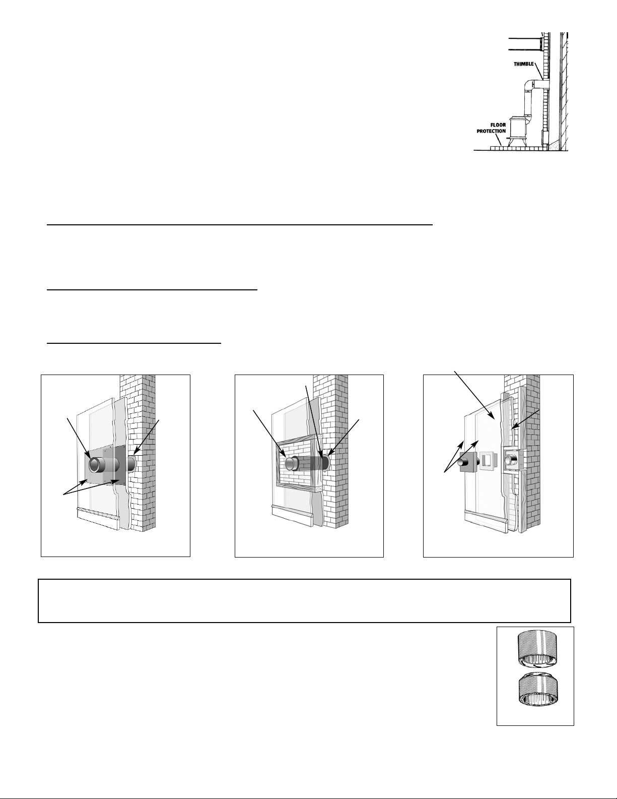
Passing Through A Combustible Wall:
With an exterior chimney, in most cases the chimney connector (or stove pipe) will need to pass through a combustible
wall. The following are acceptable methods:
A.
Use a section of Solid Insulated Prefabricated Metal Chimney to connect to the chimney - Use a section of insulated
prefabricated 2100° Class A chimney pipe listed to UL 103 HT (at least 1” of insulation or greater) the same inside diameter
as the stove pipe and maintain a 9” air space between the wall of the prefabricated chimney and the combustible wall. This
section of chimney pipe can be supported by a sheet metal plate securely fastened to the combustible wall, with a hole cut in
the middle of it. This will close the gap around the chimney pipe and the framed opening. (See Diagram A Below)
B. Build a solid brick surround around a tile liner - Frame a 3.5” thick brick surround into the combustible wall you need to
pass through. Maintain a minimum 12” brick separation from the clay liner to combustibles. The minimum 5/8” thick clay
liner should be cemented in place and run from the outer surface of the brick to the inner surface of the chimney. (See
Diagram B Below)
C.
There are also UL Listed kits available that are specifically designed for passing through a combustible wall. For more
information on these kits, please contact Woodstock Soapstone Company. Please note: there are several UL listed wall pass
through kits available, always follow the specific manufacturers installation instructions. (See Diagram C Below)
For other methods, please refer to NFPA 211.
REMEMBER, UNPROTECTED SINGLE OR DOUBLE WALL STOVE PIPE SHOULD NOT PASS THROUGH A
COMBUSTIBLE WALL OR CEILING TO CONNECT TO THE CHIMNEY. YOU MUST USE AN APPROVED METHOD
WHICH PROVIDES GREATER PROTECTION THAN SINGLE OR DOUBLE WALL PIPE.
Prefabricated Metal Chimneys:
For high efficiency, freestanding woodstoves, like your Woodstock Soapstone stove, a Prefabricated
Metal Chimney must be listed as Class A and carry a UL Listing of 103 HT (high temperature). The “UL
103 Type HT Class A” prefabricated chimney will have a temperature rating of 2,100° F.
There are prefabricated chimney systems that are approved only to 1,700° F and are suitable only for
fireplace inserts or factory built fireplaces. DO NOT use these with your Woodstock Soapstone stove.
At the point of the first penetration of a combustible surface (i.e., wall or ceiling) all subsequent
venting components need to be prefabricated “UL Type HT Class A”. If your prefabricated chimney
Connecting your stove to a
masonry thimble.
The minimum clearance for a single wall
metal stovepipe and terra cotta thimble at the
chimney connection is 12”
A.
Using a Prefabricated Metal Chimney section
to connect to an existing masonry chimney
located behind a combustible wall
Use a UL listed and approved wall pass thru kit.
B.
Refractory
Cement
Insulated
section of
factory built
chimney
Sheet
Steel
Supports
9”
9”
9”
9
Refractory
Cement
Fireclay Thimble
12”
12”
12”
12
Stainless Steel
Connector
C.
UL listed
insulated
thimble
Minimum required
air space
Listed wall
protector &
cover shield
UL 103 HT Stainless
Chimney Connection
3
goes through a living space it must be enclosed, and that enclosure must conform to clearance standards for the prefabri-
cated chimney. Your chimney must pass through your roof and extend above the roof line in accordance with code stan-
dards. Please refer to height requirements on Page 2.
Prefabricated Chimney Configurations
The diagrams below represent the most common and acceptable installations using prefabricated chimney pipe. The
necessary components are listed and shown in their appropriate locations. These components are Class A listed to U.L.
103HT (tested to 2100 degrees F.) Only components listed to UL 103HT can be used to install your wood stove.
Installation instructions are described below as examples only. More detailed instructions are available through
Woodstock Soapstone or the pipe manufacturer. ALWAYS FOLLOW THE SPECIFIC MANUFACTURER’S
INSTALLATION INSTRUCTIONS.
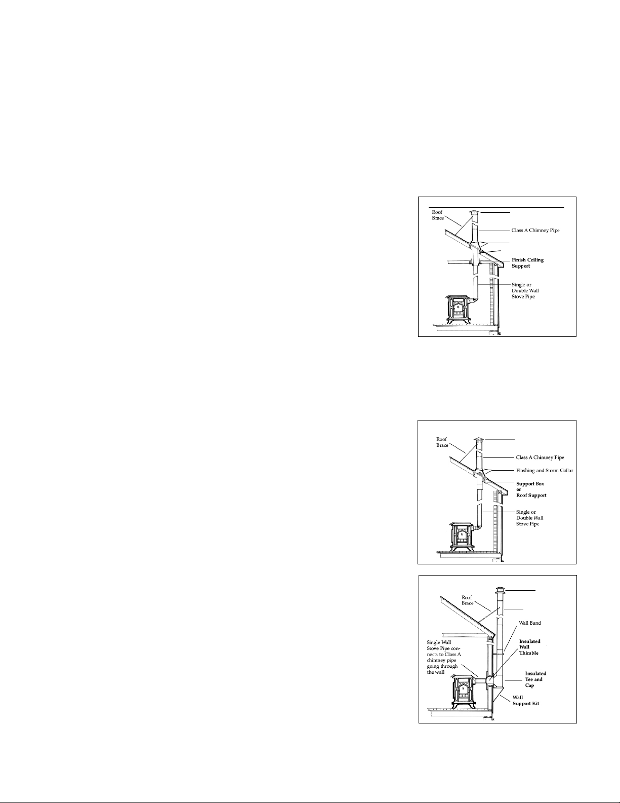
Installation 1- Flat ceiling through the roof
First, determine where the stove will be placed. Pay close attention to all required
clearances for the stove and connector pipe. Next, use a plumb line to locate the fin-
ish ceiling support in the ceiling above. Cut the appropriate sized hole in the ceiling
and frame in the necessary supports to secure the ceiling support. Install the pipe
adapter onto the first section of chimney pipe, and lower them into the ceiling sup-
port. Use an insulation shield in the attic to keep any insulation away from the pipe.
If the attic is a living space the chimney pipe must be fully enclosed. As the pipe
extends through the roof, install the appropriate flashing and storm collar to keep the
weather out. As the height of the chimney increases to meet code, it may be neces-
sary to install a roof brace (typically recommended at 5’ intervals). All chimneys
should have the appropriate cap installed at the top to reduce wind and weather
related downdrafts as well as deter any animals from building nests. The connector
pipe should extend from the flue collar of the stove to the pipe adapter at the ceiling
support. The male (crimped) end should always point down toward the stove. Be sure that each joint has enough overlap
for a secure connection. All connections should be fastened with screws, including at the flue collar and pipe adapter.
(Please refer to the manufacturers full set of installation instructions)
Installation 2- Pitched/Cathedral Ceiling through the roof
Determine where the stove will be placed. Be sure all clearance requirements are satisfied. Choose the appropriate
support for your installation (support box or roof support). Use a plumb line to
locate the support in the ceiling above. Cut the appropriate sized hole in the ceiling
and install the necessary framing to secure the support. Install the support accord-
ing to its specific instructions. Be sure that the support hangs down below the ceil-
ing far enough to maintain proper clearance for the connector pipe (steeper slopes
require more chimney pipe below the ceiling). Install the pipe adapter to the first
section of chimney pipe and lower it into the support box (or connect it to the bot-
tom of the roof support). As the pipe extends through the roof, install the appropri-
ate roof flashing and storm collar. Install the proper chimney pipe lengths to meet
code and recommended chimney height. It may be necessary to install a roof brace
for stability. Always install the appropriate cap to the top of the chimney. Double
wall connector pipe is recommended for installations that have 8’ or more from the
stove to the chimney. Be sure that all joints in the connector pipe are secure and fas-
tened with screws, including at the flue collar and chimney pipe adapter. (Please
refer to the manufacturers full set of installation instructions)
Installation 3- Through the wall
This installation requires the use of an insulated wall thimble to penetrate a com-
bustible wall. Typically a 9”-12” chimney pipe and pipe adapter will pass through
the thimble and make the connection between the interior connector pipe and an
insulated tee with a clean out on the outside of the bulding. The tee and chimney
rising up from it rest on a wall support designed to bear the weight of the chimney.
Install lateral supports as specified as the chimney rises along the exterior wall. The
appropriate flashing and storm collar should be installed if the chimney penetrates
an eave or overhang. An offset of 15 or 30 degrees may also be used to go around an
overhang. As the chimney extends above the roof to meet code recommended
heights it may be necessary to install a roof brace. (Please refer to the manufacturers
full set of installation instructions).
Installation 1- Flat ceiling through the roof
Installation 2
Pitched/Cathedral Ceiling through the roof.
Class A
Chimney Pipe
Installation 3- Through the Wall
Attic Insulation Shield
4
Chimney Cap
Chimney Cap
Chimney Cap
Flashing & Storm Collar
Stovepipe (Connector Pipe):
Connector pipe is either single wall (sheet metal) or double wall (sheet metal outer pipe with a stainless steel inner
pipe). We strongly recommend 22 gauge pipe (26 or 28 gauge is too thin for use with a woodstove). The connector pipe
should be 6 inch diameter to match the flue collar of the stove. If your connection to either a masonry chimney or prefab-
ricated chimney system is more than 8 feet tall, we recommend the use of double wall connector pipe. If you need to
reduce clearances for your connector pipe installation, double wall connector pipe would be recommended. All pipe con-
nections, including at the flue collar, must be secured with screws. DO NOT USE GALVANIZED SINGLE WALL PIPE.
Connector pipe is designed to connect your stove to your masonry lined or approved prefabricated chimney system.
CONNECTOR PIPE SHOULD NEVER BE USED AS A CHIMNEY AND SHOULD NEVER PASS THROUGH A
COMBUSTIBLE WALL, CEILING, WINDOW, CLOSET, OR ROOF. At the point where your stovepipe meets the
chimney, you must either vent into a masonry chimney with approved non-combustible transition, or a prefabricated
chimney system with a specially designed transition piece.
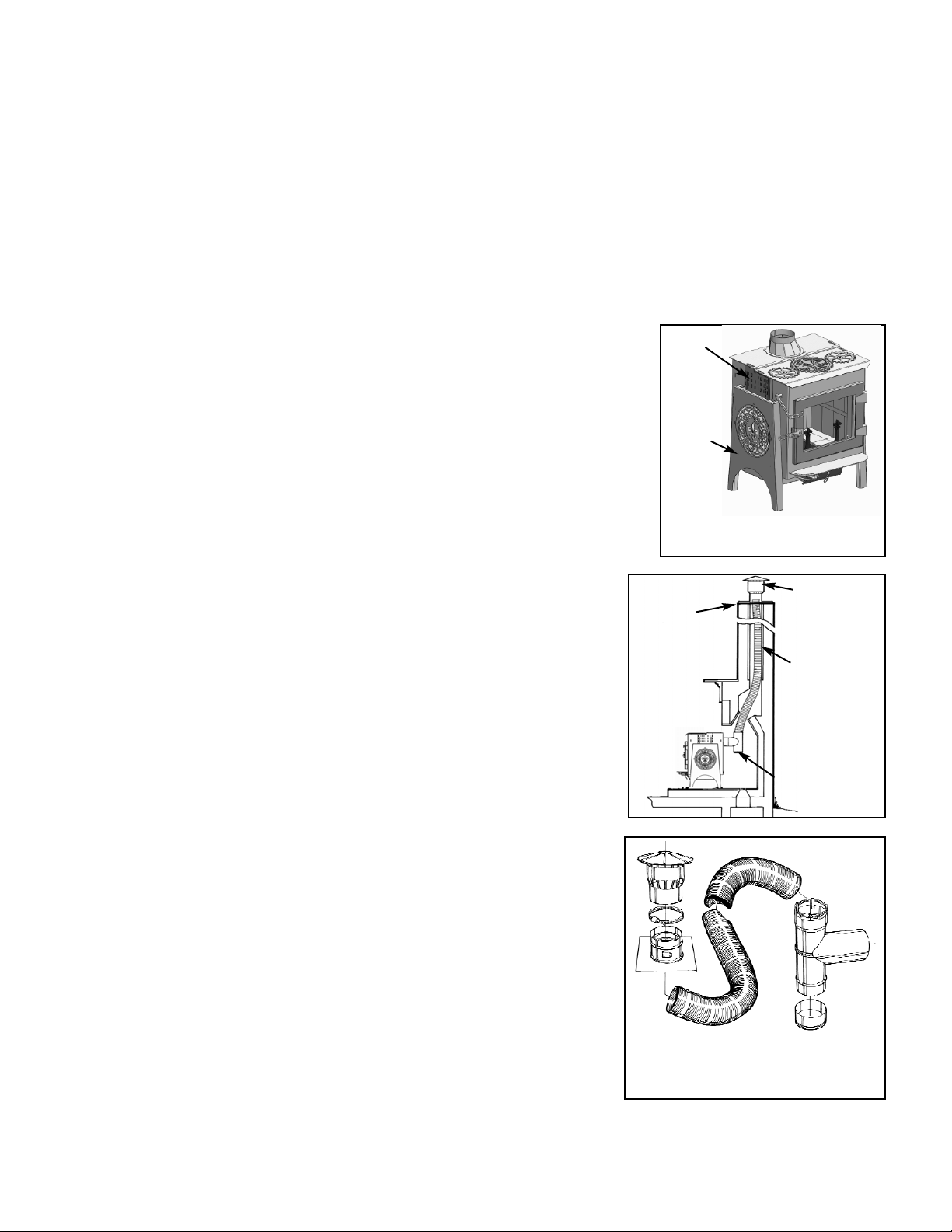
FIREPLACE INSTALLATION
Your Model 210 Ideal Steel Hybrid Woodstove has variable height legs, giving you
a greater range of flue heights for ease of installation when venting through an existing
fireplace. The variable height legs have a range of 5”. The height adjustment is in 1”
increments. The centerline height of the rear flue exit at the lowest leg height is 24.5”.
Installing the Ideal Steel Hybrid soapstone stove in a fireplace setting is a great way to
enjoy the view of the fire, while greatly increasing the efficiency and reducing heat loss
to the fireplace chimney. PLEASE NOTE: You cannot have an ash pan if you are set-
ting the stove to 30.5” .
We do not recommend placing the stove inside the fireplace, as it would make rou-
tine maintenance such as cleaning the combustor more difficult, and much of the
heat radiating off the stove would not circulate into the room.
The preferred method for installing a stove in front of a fireplace is by running
a stainless steel ‘flex’ liner down the chimney, connecting it to the stove at the fire-
place. Chimneys with large flues should be relined to achieve proper draft. If the
chimney does not have flue tiles or if the tiles are cracked or compromised, an
additional insulating material must be used.
It is important that there be a secure connection between the stove and the flue
liner. It is NOT acceptable to simply install a plate in front of the fireplace and run
a stovepipe through it. The stove pipe must connect with the liner for a continuous
outlet to the top of your chimney.
Stainless steel flex liner kits come in a variety of lengths and are readily avail-
able. These kits include a flexible stainless steel pipe, tee with snout & clean out, a
block-off plate for the top of the chimney, and a cap. Please contact Woodstock
Soapstone Company for more information on these kits. ALWAYS FOLLOW
THE SPECIFIC MANUFACTURER’S INSTALLATION INSTRUCTIONS.
If the fireplace surround is clad in wood trim, the proper clearance to a com-
bustible will need to be maintained. Please refer to the clearance charts on pages
7-10. An unprotected wood mantel needs to be a minimum of 30” from the top of
the stove. If a mantel shield is installed that clearance can be reduced to 12”.
DO NOT VENT YOUR WOOD STOVE THROUGH A FACTORY BUILT FIRE-
PLACE UNLESS IT IS SPECIFICALLY LISTED FOR SUCH AN INSTALLA-
TION . Most factory-built fireplace chimney systems are only rated to 1,700° F,
which is not sufficient for a freestanding wood burning stove.
Cap
Top Plate
Stainless
Liner
Cleanout
Tee & Snout
Components of a standard liner kit:
Tee with clean out& snout, stainless
flex liner, top block-off plate & cap.
5
Ideal Steel Hybrid shown
variable height legs.
Side Support Rail
Side Fender
(cover)
FLOOR PROTECTION REQUIREMENTS
Your Woodstock Soapstone stove must be set on an approved hearth or floor protection.
The hearth protects your floor from two hazards:
• Heat Transfer: Heat radiation from the bottom, front, and sides of the woodstove
• Ember Protection: Sparks and hot coals that may fall out during ash removal and reloading of firewood
DO NOT INSTALL YOUR WOODSTOCK SOAPSTONE STOVE ON A COMBUSTIBLE SUR-
FACE (WOOD, CARPET, LAMINATE, OR VINYL, FOR EXAMPLE).
Even if you have a stone or tile overlay on wood, it is still considered combustible since the surface materials will not
provide adequate heat transfer protection.
Your stove MUST sit on one of the following:
• A hearth pad of solid masonry (brick or tile on concrete and mortared in place)
• A prefabricated hearth pad listed to UL1618 approved standards. These pads are made to be placed on an existing
floor. Woodstock Soapstone Company has a good selection of these pre-made pads.
• A custom designed pad constructed of approved non-combustible materials which will protect the floor from sparks,
hot coals, and ashes; and prevents heat from being transferred onto the floor beneath.
IF YOU CHOOSE TO BUILD YOUR OWN HEARTH PAD
1) Start with a plywood base or subfloor.
Over this apply:
2) a layer of insulating board with an R-Value of at least 0.41. Depending on the mate-
rial you choose, the insulating board can be as little as 1/2” thick. For additional
help with material specifications, contact Woodstock Soapstone Company at 1-800-
866-4344 or [email protected].
Over this apply:
3) 1/4” or greater of a decorative, non-combustible material such as tile, slate, stone,
or brick. Use mortar or grout to set the material in place, then grout the seams.
Specifications for floor protectors
may be listed in terms of R-value,
K-value, or C-value. To convert K
or C value to R-value use the fol-
lowing formulas.
K to R: R=1/K x T (Thickness of
the alternate material)
C to R: R=1/C
Once alternate materials have been
converted to R-values, the values
of multiple layers can be added to
determine the combined protection.
If the overall R-value meets or
exceeds the specified .41 then the
materials are acceptable.
DO NOT
USE: Old-fashioned stove boards that were commonly sold in hardware stores as they DO NOT have ade-
quate protection and ARE NOT approved for primary floor protection under your stove.
Hearth Rugs also ARE NOT meant to be used as primary hearth protection. These are made to be used in addition to
an approved hearth, and are an auxiliary decorative protection. They are not a substitute for an approved hearth pad.
You can build your own hearth pad to fit
your decor. The hearth pad must meet a
minimum R value of .41
trim
board
1/4” slate or tile
3/4” plywood
or subfloor
non-combustible
insulation board
6
R-values of common hearth materials:
Ceramic Tile 1/4” 0.020
Granite 1/4” 0.020
Slate 1/4” 0.025
Cement Mortar 1/2” 0.025
Cementboard 1/4”-1/2” 0.20-0.39
Common Brick 2.25” 0.450
Common Brick 4.00” 0.800
Mineral/Ceramic Fiber Board 1/2” 1.10-1.470
Please Note: Always check with the manufacturer of the hearth material used
to verify the R or K value.
K Values cannot be added. Convert to R value before adding multiple layers.
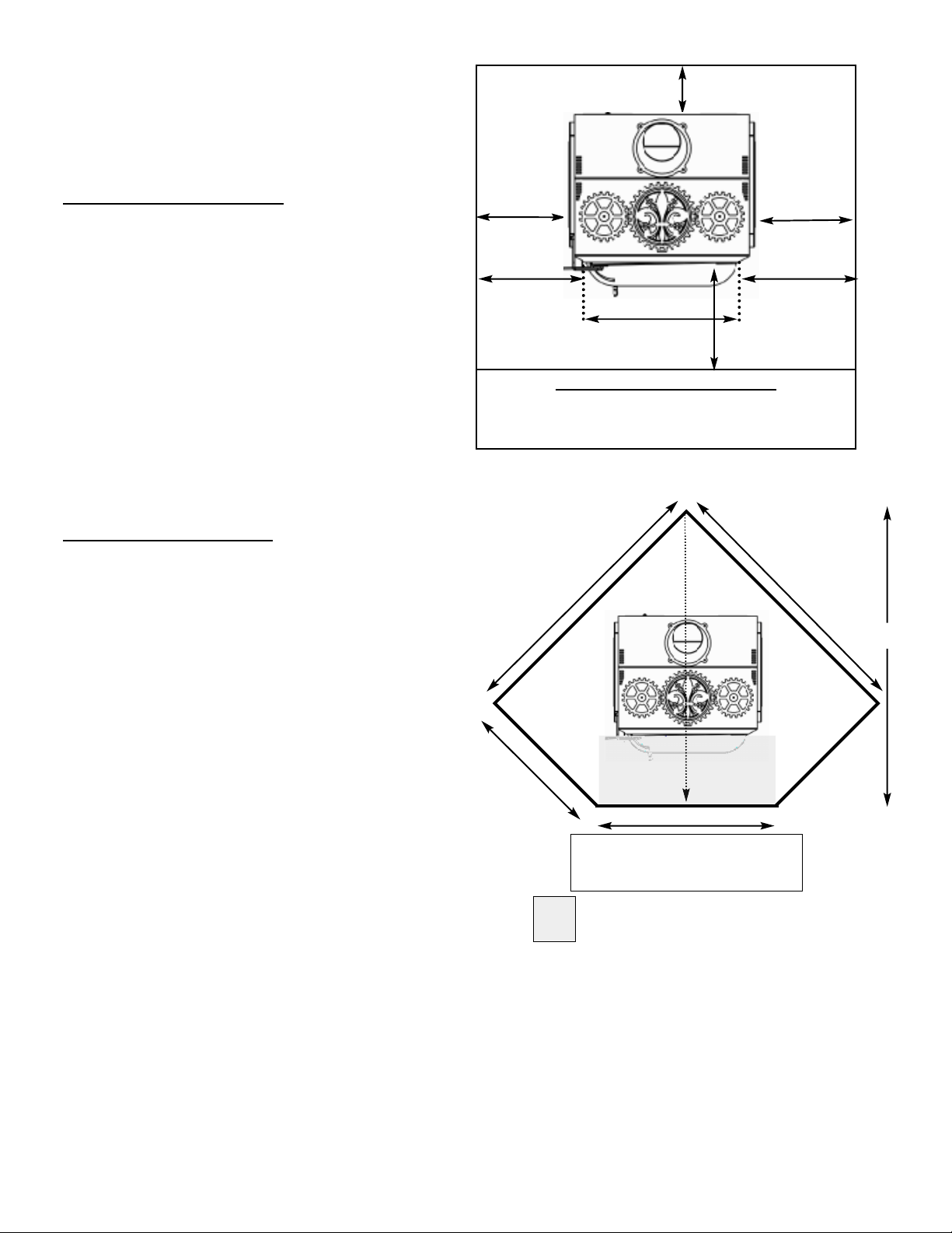
Hearth Sizing:
Clearances for your Ideal Steel Hybrid stove on the front,
back and sides must be taken into consideration when
determining the placement and size of your floor protection.
The floor protection must extend under any horizontal con-
nector pipe and 2 inches beyond each side of that connector.
PARALLEL HEARTH PAD
MINIMUM DIMENSIONS
A. Floor protection in front of load door opening = 16”
B. Protection to either side of the loading door/ash
door opening = 8”
C. Floor protection non-loading door sides = 6”
D. Floor protection behind stove (top vent or rear
vent) = 6”
Minimum hearth size in a parallel installation is 46”D x 38”W.
Recommended size is 48” D x 48”W or larger.
A 48” x 48” square hearth pad will allow for
6” behind the stove, 11” on either side, and 18”
in front of the stove. The hearth pad must have a minimum R value
of 0.41 (1/2” of “cementboard' covered with 1/4” of tile or stone).
CORNER HEARTH PAD
Minimum hearth size in a corner installation must be 54.5”x
54.5” (with the front corner cut off). NOTE: To achieve the
minimum hearth dimension, the stove must be top vented.
Calculating a Corner Hearth Pad (per NFPA 211):
A=C x 1.414 + W/2 + D + Front Hearth Requirement
A =distance from corner to the front of the hearth pad
C = clearance from rear corner of appliance to wall (rear heat
shield is recommended but not required)
1.414 = a constant
W/2 = one half the appliance width (12.625”)
D = appliance depth (23.5”)
Front Hearth Clearance= 16”
Example:
Ideal Steel with the Rear Heat Shield & Pipe Shield
A= 6” x 1.414 + 12.625 + 23.5”+16” A= 60.5”
WALL PROTECTION
The Model 210 Ideal Steel Hybrid stove has been tested to UL standards for clearances to combustible walls. The mini-
mum clearances to unprotected walls are as follows:
Minimum clearances with no heat shields to unprotected combustible walls:
From the back------------------ 14”
From the sides-------------------19”
Do not assume that a wall is not combustible because it has a nonflammable surface. A wall with any combustible
materials in it must be considered combustible. For example, a brick wall attached to wood studs is considered a com-
bustible wall. Over time, heat will pass through bricks and heat the wood, lowering the ignition temperature of the
PARALLEL HEARTH PAD
Measurements taken from stove body
Stove Body Width 25.25”
Stove Body Depth 23.5”
A=60.5”
54.5”
54.5”
31.5”
33”
CORNER HEARTH PAD
Ideal Steel Hybrid shown above
centered left to right
7
C
A
B
B
D
Door Opening
C
60.5”
Grayed area represents the front hearth clearance
requirement of 16”, which must extend 8” to the
right and left of the loading door opening.
studs, possibly resulting in a fire. As waves of radiant heat energy meet a combustible object,
heat is absorbed and the temperature of the object is raised, which can result in spontaneous
combustion. Similarly, wood-framed walls which are covered with tile, stone or fire-rated
sheetrock must be considered combustible. Fire-rated sheetrock is also considered combustible
due to the paper covering.
If you wish to install your stove closer to a combustible wall than standard clearances will per-
mit, you can either attach an approved stove & pipe shield, or mount a ventilated, non-com-
bustible shield on the wall.
Stove and Pipe Shields:
Clearances can be reduced by attaching an approved heat shield, part #IS-256 and pipe
shield, part #W-413. Woodstock Soapstone Company carries heat shields specifically designed
for this stove. When using one or both of these shields, clearance is measured from the back of
the shield to the combustible wall. The clearance behind the stove can be reduced to 6 inches.
The clearance behind the pipe can be reduced to 6 inches.
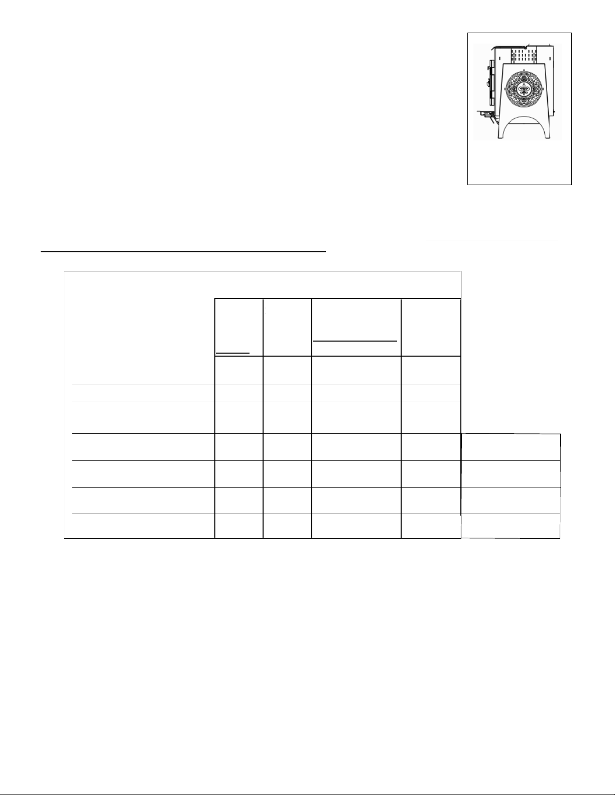
Clearance Table:
The Ideal Steel Stove can be installed at a 14” clearance with no additional protection, if the stove pipe is top vented,
and the provided shield, is used to cover the rear flue cover plate. To further reduce the rear clearance to 6”, you must
attach an approved rear heat shield and a 36” pipe shield.
*
These clearance reductions meet or exceed requirements of NFPA 211, Standard for Chimneys, Fireplaces, Vents, and Solid Fuel
Burning Appliances. Approved NFPA 211 clearance reduction methods DO NOT allow stove clearances to be reduced below 12”.
NFPA WALL SHIELDS MUST BE SIZED TO NFPA 211 SPECIFICATIONS. CONSULT NFPA 211 AND A QUALIFIED EXPERT
BEFORE IMPLEMENTING THESE REDUCTIONS.
The only approved method allowing for a rear stove clearance less than 12” is the Approved Rear Heat Shield (#IS-256) provided by
Woodstock Soapstone Co. If your installation requires the use of the Approved Rear Heat Shield call 1-800-866-4344.
• These clearances apply to walls, ceilings, furniture and other combustibles.
• The 36” Vertical Stack Shield attaches to the back of the stove pipe and prevents excess heat from being radiated from the pipe.
Heat shield protection is only required for the first 36” of vertical connector pipe.
• At least 30” is required from the front of the stove to combustibles (such as curtains, wall hangings, and furniture).
The same clearances from your stove and stove pipe apply to both fireplace and freestanding installations. Be
particularly careful to check clearances to a wood mantel or a wood fireplace facade. You must maintain a 30” clearance
to an unprotected wood mantel. See Fireplace Installations on Page 5.
Clearance Table For Model 210 IDEAL STEEL
Type of Installation Top Vent Rear Vent Rear Vent with elbow Stove Sides
Stoveck Pipe goes
Type of protection
Stove Back Stovepipe
No Protection 14” 14” 23” 15” 19”
With 36” Pipe Shield 14” 6” 19”
With Approved Rear Heat Shield 6” 14” 6”
* 19”
(Part #IS-256) and 36” Pipe Shield
3
1
/2” thick Masonry Against 12” 12” 20” 12” 13”
Combustible Wall*
3
1
/2” thick Masonry with 12” 12” 14” 6” 12”
1” ventilated airspace*
24 ga. sheet metal with 12” 12” 14” 6” 12”
1” ventilated airspace*
1/2” thick non-combustible 12” 12” 14” 6” 12”
insulation board with 1” airspace
*
Clearance from
stove back, top
vent, with
stove pipe
which goes
straight up
Clearance
from stove
back and pipe,
which goes
straight back
Clearance from stove back
and vertical single wall
connector pipe
with elbow at stove back
8
Rear heat shield & pipe
shield reduce required
rear clearance to 6”
See note below regarding NFPA
211 clearance reduction methods
and implementation.
See note below regarding NFPA
211 clearance reduction methods
and implementation.
See note below regarding NFPA
211 clearance reduction methods
and implementation.
See note below regarding NFPA
211 clearance reduction methods
and implementation.
*Controlling clearance
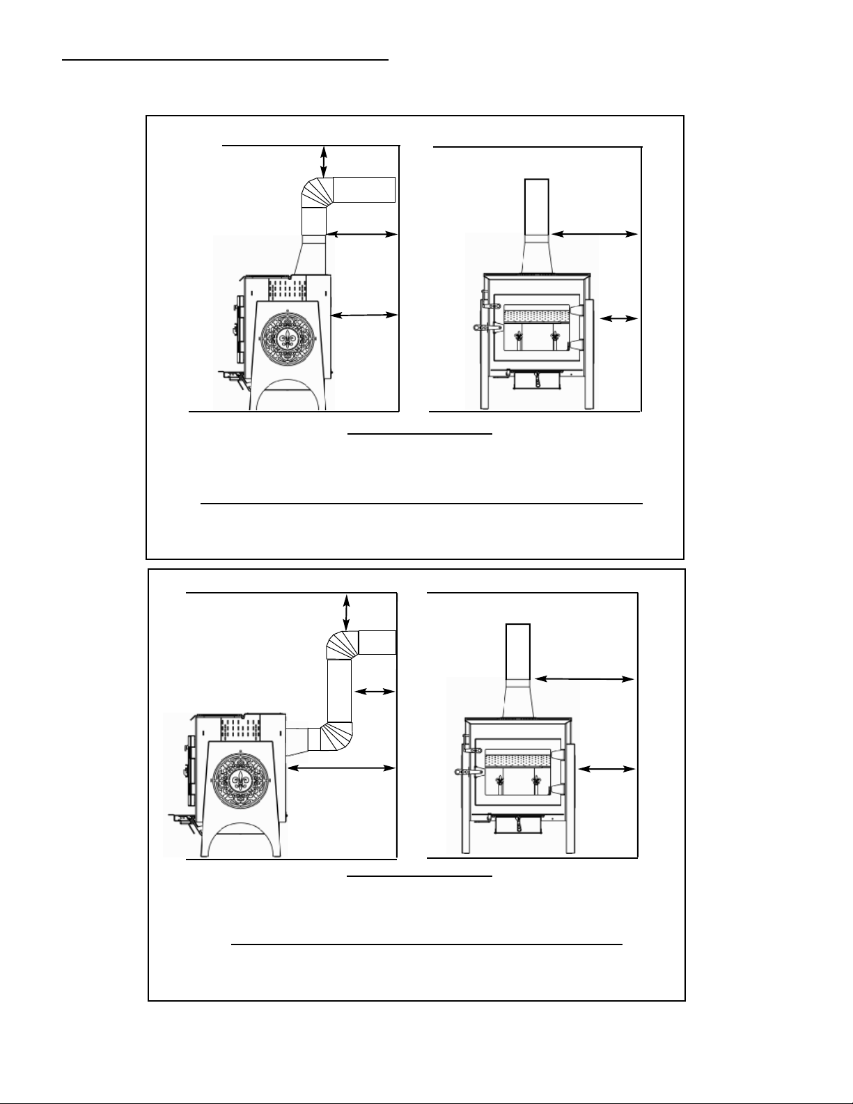
CLEARANCE INSTALLATION DIAGRAMS
B
C
C
A
B
2) Parallel Installation, Single Wall Pipe, Back Vent
NO HEAT SHIELD
A. Back of stove to wall = 23” D. Side of stove to wall = 19”
B. Back of pipe to wall = 15” E. Side of pipe to wall = 29.5”
C. Above pipe to ceiling = 18”
WITH REAR SHIELD & PIPE SHIELD ATTACHED
A. Back of stove shield to wall = 14” D. Side of stove to wall = 19”
B. Back of pipe shield to wall = 6” E. Side of pipe to wall = 29.5”
C. Above pipe to ceiling = 18”
WITH REAR HEAT SHIELD & PIPE SHIELD ATTACHED
A. Back of stove shield to wall = 6” D. Side of stove to wall = 19”
B. Back of pipe shield to wall = 6” E. Side of pipe to wall = 29.5”
C. Above pipe to ceiling = 18”
D
9
NO HEAT SHIELD
A. Back of stove to wall = 14” D. Side of stove to wall = 19”
B. Back of pipe to wall = 15” E. Side of pipe to wall = 29.5”
C. Above pipe to ceiling = 18”
1) Parallel Installation, Single Wall Pipe, Top Vent
A
E
E
D
NO HEAT SHIELD
A. Stove corners to side walls = 10.5”
B. Pipe to side walls = 17”
C. Pipe to corner = 17”(determines placement)
WITH REAR SHIELD & DOUBLE WALL CONNECTOR PIPE
A. Stove corners to side walls = 6” (determines placement)
B. Back of pipe shield to side walls = 6” (Double Wall Connector Pipe)
C. Pipe to corner = 6” (Double Wall Connector Pipe)
B
4) Corner Installation, Single Wall Pipe, Back Vent
C
C
TOP VENT
NO HEAT SHIELD
A. Stove corners to side walls =6” (determines placement)
B. Pipe to side walls =17”
C. Pipe to corner =17”
WITH REAR HEAT SHIELD & PIPE SHIELD ATTACHED
A. Stove corners to side walls = 6” (determines placement)
B. Pipe to side walls = 17”
C. Pipe to corner =17”
3) Corner Installation, Single Wall Pipe, Top Vent
CLEARANCE INSTALLATION DIAGRAMS
10
B
A
A
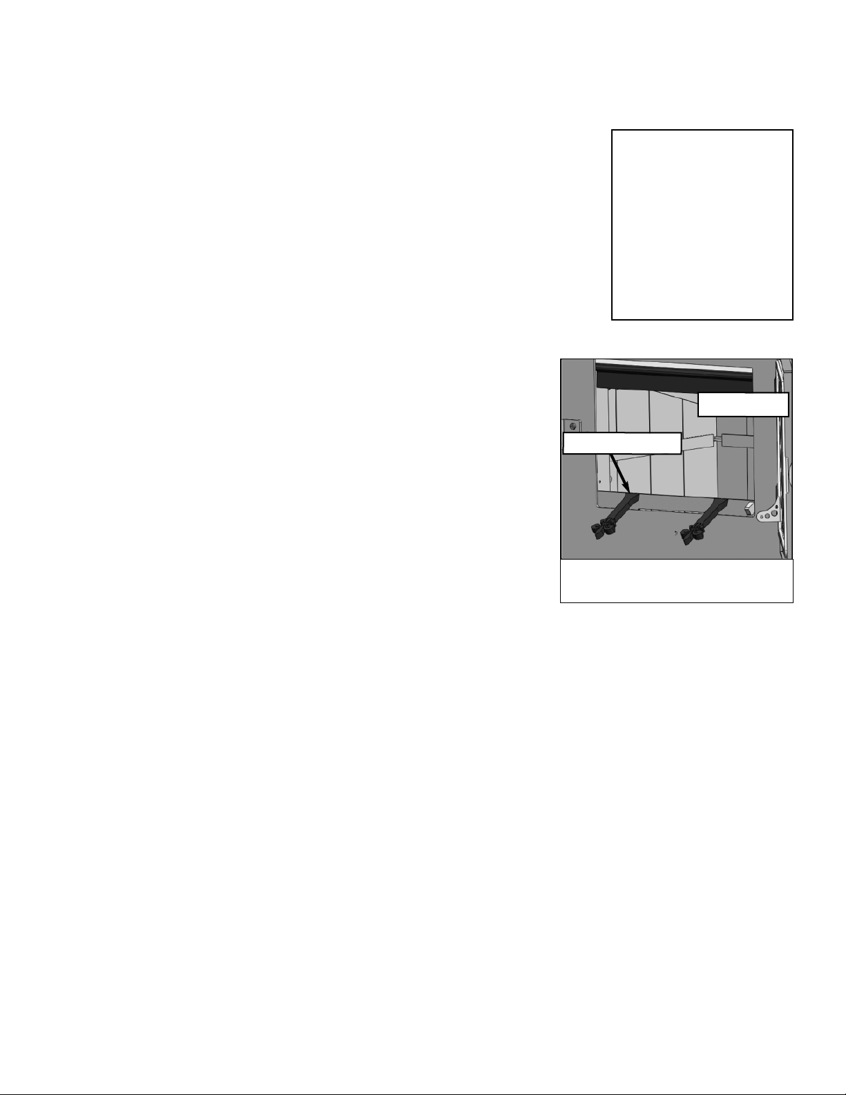
SETTING UP YOUR STOVE
Your Model 210 Ideal Steel Hybrid woodstove has been shipped assembled except for four parts:
1) Changing the height of the stove; 2) the flue collar, 3) the ash lip 4) and door handle.
Your stove is factory set at the 33.5” height, if you need it raised or lowered, follow the directions below. The ash lip,
flue collar, door handle, as well as the center burner are packed inside the firebox of the stove. All necessary hardware
and instructions are also packed in the firebox. Any optional items such as heat shields will be packed separately.
(1) How to adjust stove height:
The Ideal Steal Leg system has both a structural element as well as a customizable decorative outer fender. The
structural steel legs offer a total of 5” of height adjustment in 1” increments. The decorative fender is designed to match
the height of the legs once the desired height is set. Please note: You cannot have an ash pan if you are setting the stove
at the lowest stove height of 30.5”.
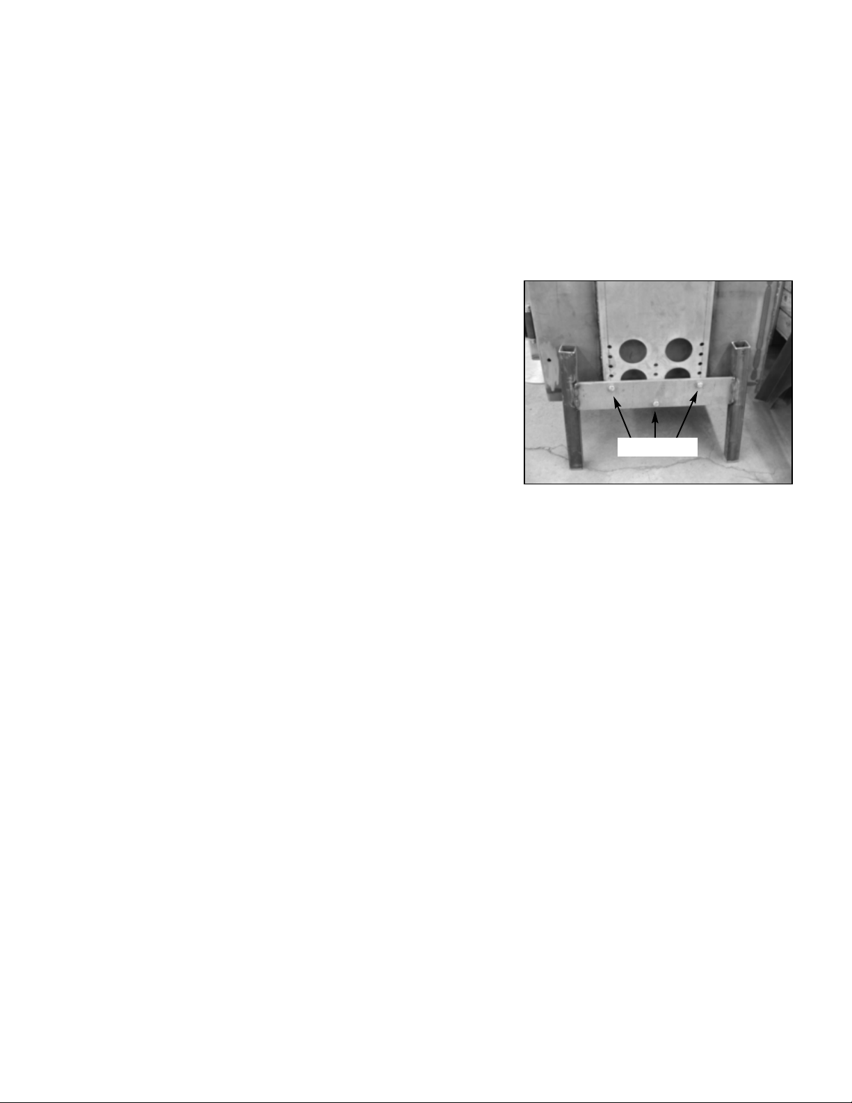
To adjust the height of the stove you will need to first remove the
decorative leg fender. a means to lift and support the stove safely and a
9/16” wrench and 9/16” socket and ratchet.
1. First remove your decorative fenders. First lift up on the fender
assembly and then swing the bottom away from the stove to remove
the fender assembly from the body of the stove, repeat the process on
the other side.
1. Raise and support one side of the stove at a time to make height
adjustments. A small automotive or bottle jack may work to elevate
the stove but be sure to use safety supports as well. Do not rely on
the jack alone for support while working on the stove. Be aware of
the air control components located at the bottom left side of the stove
to avoid damage.
2. The steel legs are attached to the body of the stove with (3) 3/8” bolts, nuts, and lock washers. Use a 9/16” socket,
ratchet, and wrench to loosen and remove the hardware.
3. Move the steel legs to the desired height setting. Each row of holes is 1” apart. Insert the bolt from the outside and
through the corresponding hole in the stove body. Place a lock washer over the bolt and secure with a nut. Be sure
that the two outside bolts are positioned in the same row. Firmly tighten each bolt and nut.
4. Repeat this process on the opposite side.
5. Reinstall the fender assemblies. Align the bottom of the fender with the legs. Lift it slightly until the lower tabs
rest over the leg bracket. Rotate the top of the fender in toward the body of the stove to align the top tabs with the
slots in the body, and push the fender down to secure it.
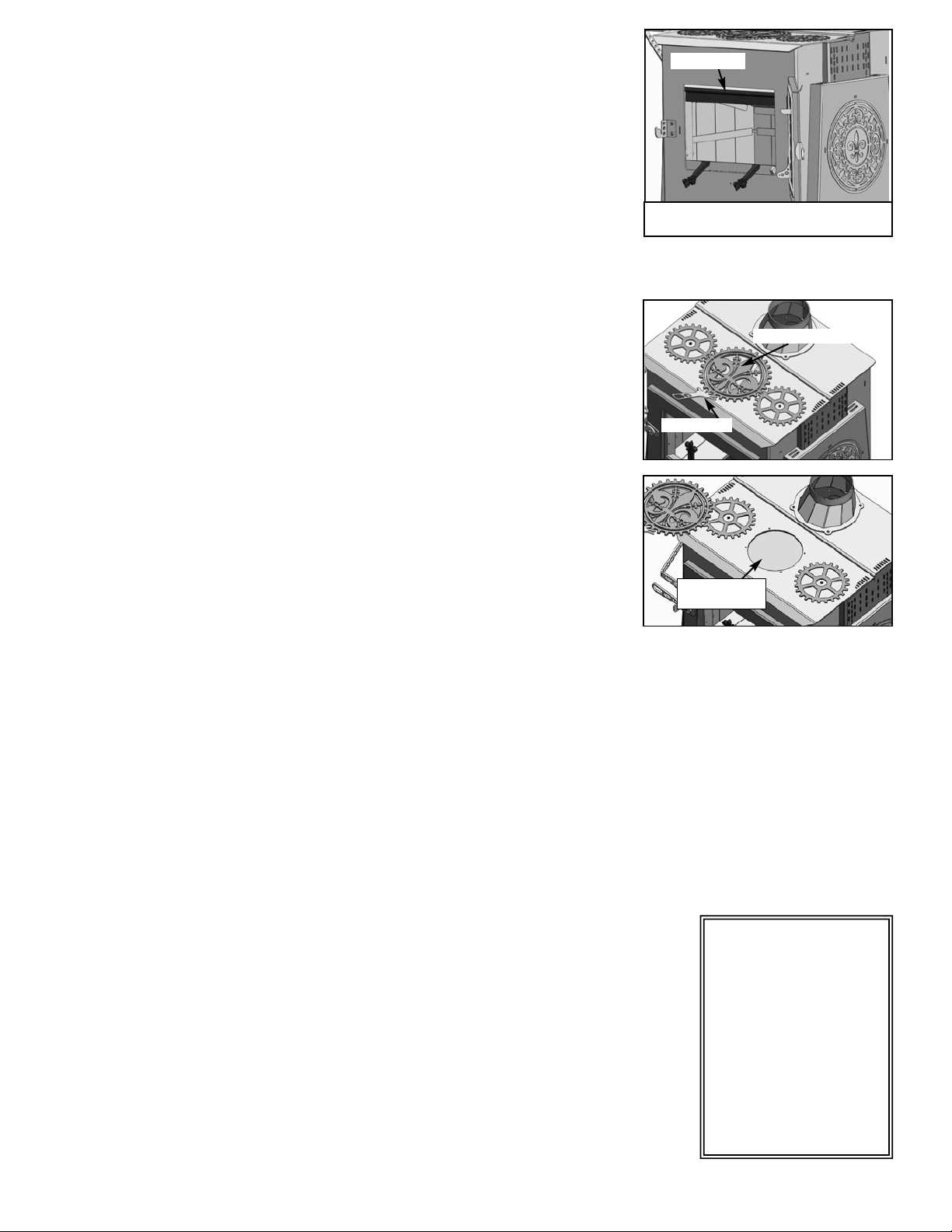
2) How to attach the Ideal Steel Hybrid flue collar & cover plate:
The Ideal Steel is designed to be vented out the top or out the rear with an easily convertible flue collar and cover
plate. Each part is secure to the stove body with 4 bolts. You will need a ½” wrench or socket and ratchet to install these
parts. The stove is shipped with the cover plate installed over the rear flue exit. The flue collar is packed inside the
firebox.
1. Decide which way you would like to vent your stove. This may be dependent on the location of an existing
chimney or the design of an existing hearth. Always pay close attention to required clearances when considering
stove placement
2. Install the flue collar in the desired location. Be sure that the gasket on it is secure and stays in place while
installing. Use four of the bolts to attach the flue collar to the stove body. The holes in the stove body are threaded
to accept the bolts. Alternate between the bolts while tightening to ensure even pressure. The bolts should be tight
enough to firmly compress the gasket. Do not over tighten.
3. Repeat the process to install the cover plate over the flue exit not being used.
Note: If the flue collar is installed on the rear flue exit, the sloped side must face the floor.
3) How to attach the Ideal Steel Hybrid Ash Lip:
The Ideal Steel ash lip is packed inside the firebox. The ash lip must be installed prior to using your stove. You will
need a 7/16” wrench or deep socket and ratchet to install the ash lip.
1. Locate the two threaded studs on the ash lip. The studs will be on the bottom side of the ash lip. The air damper
markings should be on the left as you face the stove.
2. Align the threaded studs with the holes in the flat lip that extends out from the front of the stove. Insert the studs
11
Leg Bolts
into the holes.
3. Secure the ash lip with the washers and nuts provided.
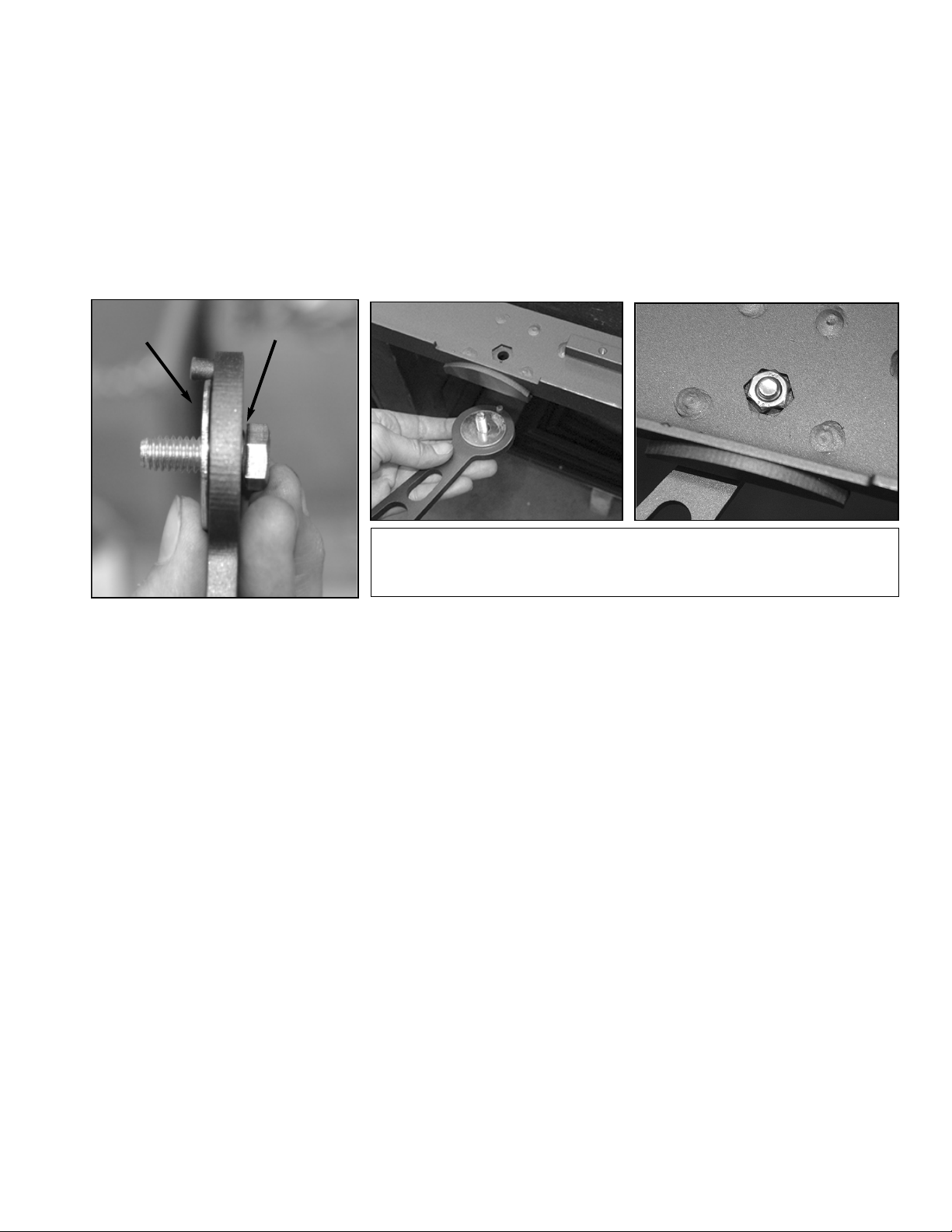
4) How to attach the Ideal Steel Hybrid Door Handle:
For shipping purposes the door handle for your Ideal Steel stove has been packed in the firebox with the appropriate
hardware for installation. You will need a ½” socket and ratchet or wrench to install the handle.
1. Slide the small wave washer onto the bolt first.
2. Place the bolt through the hole in the handle. Slide the large spacer washer over the bolt so that it is between the
handle and the exterior of the loading door.
3. Place the handle through the hole on the door and line up the pin up with the slot in the door.
4. Using a wrench and a socket and ratchet, tighten the bolt until you feel some resistance when the handle travels up
and down.
OPTIONAL ACCESSORIES
Your Model 210 Ideal Steel Hybrid wood stove has several optional add-on components depending on individual
installation needs.
1) Rear Heat Shield: Reduces the rear clearance from the back of the stove to a combustible surface from 14” to 6”. See
page 8 for additional clearance details.
2) Pipe Shield: Reduces the clearance requirement for single wall connector pipe. See page 8 for additional clearance
details.
3) Outside Air Adapter: Typically required or recommended in certain installations, including Mobile Homes (HUD
Homes), WA State, tightly sealed construction, as well as certain state wood stove change-out programs. The outside air
adapter allows combustion air to be drawn directly to the stove from the outside or ventilated crawl space. The outside air
adapter easily attaches to the bottom of the stove (over the air intake) and has a 4” round collar to attach 4” ductwork. The
connecting ductwork (usually 4” aluminum dyer vent) should only run straight back or down, and the duct should be as
short and direct as possible.
4) Side Shelf: Part PG-29 can be seen on page 31 of the manual.
5) Hearth Tools & Tool Hanger: Includes a rake, poker, shovel, and side mount tool hanger (or optional stand): Made
right in our NH Factory, choose from a variety of designs (deer, leaves, moose, fish, dogs, etc.).
12
Wave Washer
Large Washer
The large spacer washer gets sandwiched between the door handle and the
OUTSIDE of the loading door. The lock nut will secure the door handle assembly on
the inside of the loading door.
Woodstock Soapstone Company
66Airpark Road, West Lebanon, NH 03784
800-866-4344 • www.woodstove.com
MOBILE HOME INSTALLATIONS
CAUTION: THE STRUCTURAL INTEGRITY OF THE MOBILE HOME FLOOR, WALL, AND CEILING/ROOF
MUST BE MAINTAINED.
Mobile Home Prohibition:
WARNING:
DO NOT INSTALL IN SLEEPING ROOM
Because mobile homes are also referred to by HUD as
“manufactured” homes, regulations present a gray area.
Many “mobile” homes are set on a permanent foundation
and connected to public utilities. If you are installing a
stove in a mobile or manufactured home, check out the
requirements above and check with your local code offi-
cials. More questions? Give us a call Monday through
Saturday from 9 to 5 Eastern time at 1-800-866-4344.
While all stove installations have to meet National Fire
Safety codes, mobile homes are given special consideration
when it comes to installing a wood burning stove. These
additional regulations were established by the Department
of Housing and Urban Development (HUD), and result in
the following additional requirements:
1. Double Wall Connector Pipe
2. Outside Air for Combustion
3. Tie Downs for the Stove
4. Spark Arrestor on the Chimney Cap
5. Stove Grounded to Chassis
6. Stoves May Not Be Installed in Mobile Home Bedrooms
Double wall pipe must be used to connect the stove to the
chimney. This is stove pipe that is constructed with two
walls, usually with the inner wall made of stainless steel. It
reduces the required clearance to combustible building
materials and furnishings.
Outside Air must be used for combustion. Because of the
tight construction of mobile homes, wood stoves need a
way to get adequate air for complete combustion from out-
side the home in order to avoid the risk of depleting oxy-
gen in the living space. Having outside air for combustion
is a requirement for all woodburning stoves in the state of
Washington and is recommended for woodstoves in
“super tight” new construction.
Tie Downs: The stove must be attached to the floor. This
is to prevent tipping in the event the home is moved. (We
can provide tie downs for our stoves at no extra charge).
Spark Arrestor: The chimney cap must have a spark
arrestor screen. These are available with most prefabricated
chimney systems.
Grounding: The stove should be grounded to the home
chassis.
Not allowed in mobile home bedrooms: wood stoves are
not permitted for installation in bedrooms in mobile
homes.
The Outside Air Adapter attaches to the bottom of stove
over the air damper inlet. The four inch round outlet
allows you to connect ducting from the stove to the out-
doors. Woodstock Soapstone Company manufactures an
Outside Air Adapter that fastens directly over the air
damper inlet on the Ideal Steel Hybrid. It has a four-inch
collar which allows you to attach a four inch pipe, usually
flexible dryer duct, from the stove to the outside. For long
runs, the flexible pipe can transition to PVC or aluminum
pipe, if you wish.
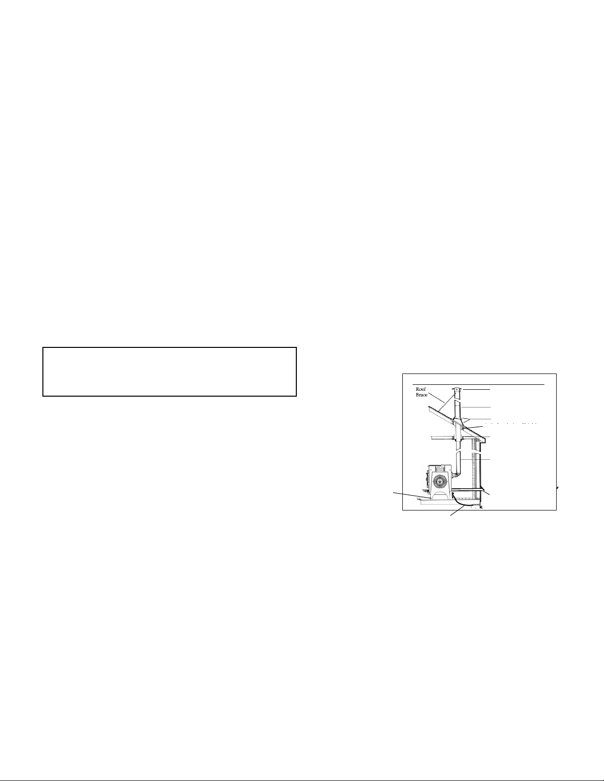
Mobile home with pitched roof
Attic Insulation Shield
Close-Clearance
Pipe
Finish Ceiling
Support
Attic Insulation Shield
Tie-Downs
Grounding
Outside Air Adapter
and Duct
Chimney Cap with
Spark Arrester
Class A Chimney
Flashing/Storm Collar
Mobile home instal-
lations require a
number of special
considerations,
including dedicated
outside air, tie-
downs, and ground-
ing to the chassis of
the mobile home.
Double Wall
Connector PIpe
13
OPERATION
Seasoning Your Stove
Both soapstone and steel need to be seasoned. The seasoning can be accomplished through a series of small to
moderate fires. Your Woodstock Soapstone Stove is an easy stove to season, because even a small fire will provide hours
of radiant heat once the stove is warm. There are two things you will notice during the first fire:
First, there will be a hot, acrid smell as the stove heats up. This smell is a result of the paint on the stove and pipe
curing. You will want to have your first fire on a day when you can open the windows in the house to provide adequate
ventilation. The odor is non-toxic and will only be present for the first few fires.
Second, there will be some condensation on the glass. This condensation is a result of any moisture being driven out
of the stove and condensing on the inner surface of the glass. It takes a couple of small fires to season the stove and
remove this excess moisture.
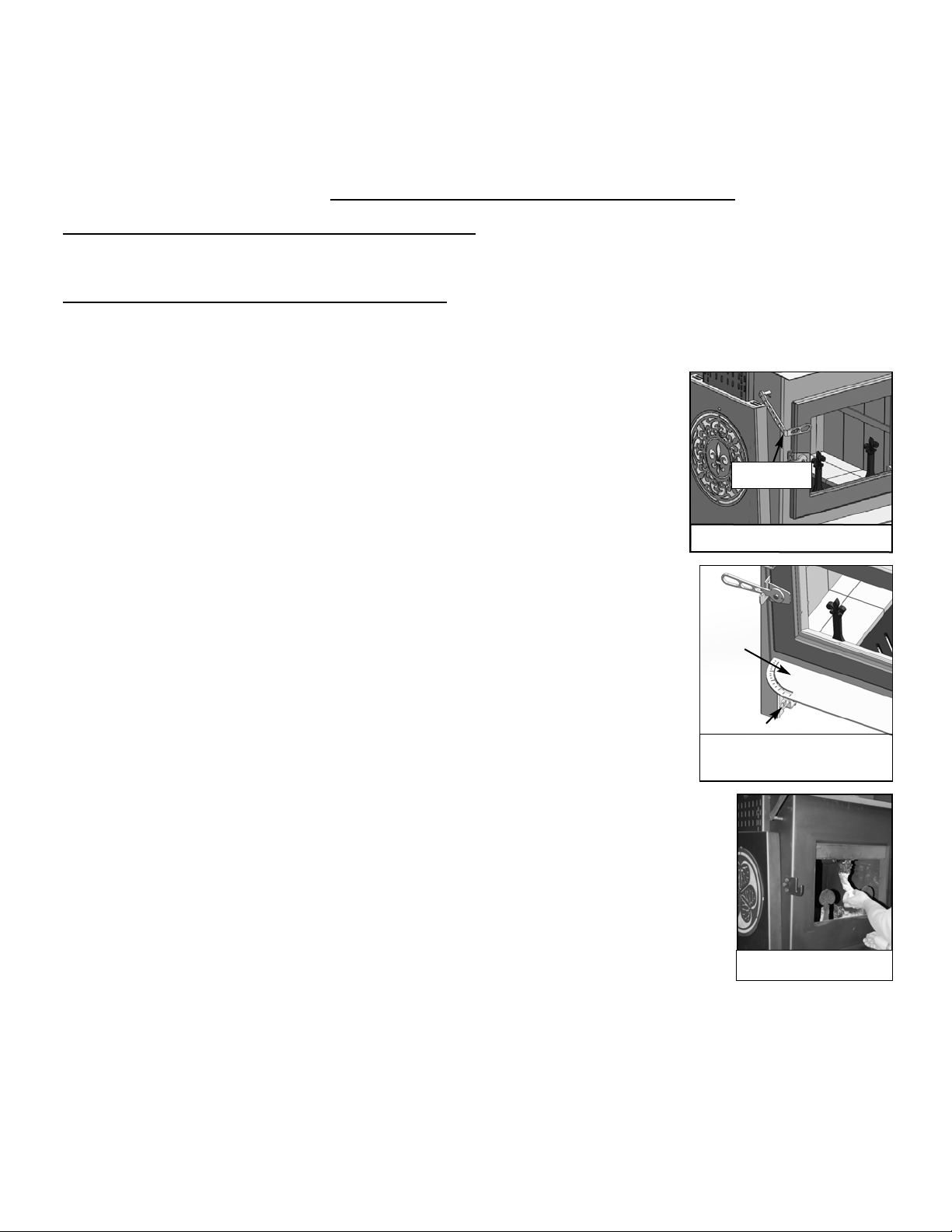
Starting a Fire And Establishing Proper Draft
1. Open the catalytic bypass. The bypass lever is located at the left front of the stove just
above the loading door handle.Lift the bypass lever up until it stops to bypass the
catalytic combustor. The bypass must be opened before opening the load door.
2. Open the combustion air damper by moving the lever in front . The air damper is
located at the lower left corner at the front of the stove. Slide the lever to the right
toward the center of the stove to the open position. The lever will stop when fully
open. Maximum air is allowed into the firebox.
3. Always confirm there is adequate draft before lighting the fire. Hold a lit match or
light a small piece of newspaper in the top of the firebox, where smoke exits. If the
flame is drawn out of the firebox, toward the flue, proceed with lighting the fire. If the
flame stands still or is pushed away from the flue exit, you must establish a good draft
before lighting a fire. A hair dryer or heat gun pointed at the flue exit is a good way to
establish draft without creating a lot of smoke. After you think you have draft, re-test
with a match.
4. Once good draft has been established, build a fire on the floor of the firebox. DO NOT
USE ADDITIONAL GRATES, ANDIRONS OR ANY OTHER METHODS TO
SUPPORT THE FUEL IN THE FIREBOX. Start with crumpled newspaper and dry
kindling.
5. Add small splits of firewood once the kindling has ignited. This will establish a bed of
hot coals.
6. Add small to medium splits onto the hot coals. Assuming the wood is dry, the fire should
spread through the wood. After about 10 minutes, close the air damper down between 3/4
and 1/2 open.
7. After the single wall pipe temperature reaches 250°-300°F, close the bypass by lowering the
handle down to the closed position. All of the smoke from the firebox will now pass
through the catalytic combustor. The combustor will generate a substantial amount of heat
as it “burns” the smoke passing through it.
8. Adjust the air control damper to a lower setting, the best burn setting is around the 1/4 open mark. Slide the lever
to the left. The closer the lever is to the face of the stove, the lower the burn rate, as less air is entering the firebox.
The final damper setting will be determined by the desired heat output from the stove, the condition of the wood
being burned, and the draft through the chimney system.
NOTE: The above procedures, times, and positions are a guide. Your conditions will vary depending upon draft,
wood moisture and size, and weather conditions.
The amount of combustion air avail-
able in the firebox is controlled by the
damper lever.
14
Ash Lip
Check draft and preheat the
chimney if necessary
The catalyst bypass lever interlocks
with the front load door
Catalyst
Bypass Lever
Air Control
Engaging the Catalytic Combustor
The catalytic combustor will start to burn the gases and particles in the smoke when the temperature of the smoke
reaches approximately 500ºF (internally) , or after about 5-15 minutes of establishing a strong fire. Each stove comes with
a magnetic thermometer. Use the thermometer to monitor your stove/pipe temperatures. The temperature of the single
wall pipe or the stove top is approximately 1/2 the temperature of the exhausting smoke, so when the thermometer on
the stove pipe reads 250ºF, it is approximately 500ºF inside. You will find that after the
combustor is engaged, the pipe temperature will often stabilize or lower, while the stove
surface temperature rises - evidence that the heat isn’t getting lost up the chimney!
Engage the combustor by lowering the bypass handle (front of the stove) down until it
closes completely. Then reduce the air damper setting to achieve the desired burn rate.
Make fine adjustments to your air control damper by moving it slightly left or right. You
may find that you can achieve the longest burn when the damper is only slightly open. In
the Ideal Steel Hybrid, allowance is made for a small amount of primary and secondary air
to enter the stove even when the damper is fully closed, and the stainless steel catalyst will
work efficiently at low to moderate firing rates, thus preventing creosote formation or
excessive smoke from your chimney.
Low & Overnight Burning
These instructions are intended as a guide to operating your wood stove. Your
timing and final damper settings will vary depending on chimney draft, type of
wood, moisture content of the wood and size of the splits. The Ideal Steel Hybrid
is simply designed and intended to be user friendly, but it will take some practice
to understand how the stove works best for you.
1. Before you open the loading door, you must fully open the catalytic bypass
and the air damper. Wait a minute or so, before opening the loading door
slowly, for a strong draft to be established to prevent smoke from spilling
back into the room. The Ideal Steel is equipped with a smoke flap which
drops down when the loading door opens. The smoke flap will help keep
smoke from spilling out of the loading door.
2. Wearing stove gloves, open the loading door and tip the andirons forward.
Stir up the hot coals. If necessary, excess ash should be removed before
reloading the firebox. If your stove has the optional ash pan, simply rake the
hot coals back and forth in the firebox to allow the loose ash to fall through the center grate into the ash pan. If
your stove does not have an ash pan, push the hot coals to one side and shovel the loose ash into a non-
combustible ash container with a tight fitting lid. Dispose of the ash properly.
Never put an ash container on a combustible surface, like a wood floor.
3. Place several small splits on top of the hot coals and allow them to ignite.
4. Load the firebox to capacity leaving roughly 2” of space for secondary combustion, with a mix of larger and smaller
splits. Tip the andirons to the upright position. Close the loading door.
5. Allow the temperature on the exterior of single wall pipe to come back up to 250°, this may only take 5-15 minutes
depending on the dryness of the wood.
6. Adjust the air damper to a low setting, around the 1/4 open mark, by sliding the lever to the left.
7. Close the catalytic bypass by lowering the lever until it stops.
8. Initially the fire may appear to die out. This may cause a small amount of soot to collect on the glass. Any buildup
on the glass should go away with higher t emperature burns.
Never burn the stove with the air damper fully open except when kindling a fire or reloading the firebox.
Never build a roaring fire in a cold stove. It takes at least 30 minutes to heat the soapstone panels of the Ideal Steel,
if equipped. Attempts to reach high temperatures very quickly could result in damage to the steel or soapstone parts.
CAUTION
NEVER USE GASOLINE,
GASOLINE TYPE LANTERN
FUEL, KEROSENE, CHAR-
COAL LIGHTER FLUID OR
SIMILAR LIQUIDS TO
START OR “FRESHEN UP” A
FIRE IN THIS STOVE. KEEP
ALL SUCH LIQUIDS WELL
AWAY FROM TH E ST OVE
WHILE IT IS IN USE.
15
Door Open
Andiron Plate
In this picture, andirons have
been pulled forward for loading.
Burning for Higher Heat Output
These instructions are intended as a guide to operating your wood stove. Your timing and final damper settings will
vary depending on chimney draft, type of wood, moisture content of the wood and size of the splits. The Ideal Steel
Hybrid is simply designed and intended to be user friendly, but it will take some practice to understand how the stove
works best for you.
1. Before you open the loading door, you must fully open the catalytic bypass and the air damper. Wait a minute or so
to establish a strong draft. This will help to keep smoke from spilling into the room.
2. Open the load door and tip the andirons forward (see image on pg 15). Stir up the coals and remove excess ash as
needed.
3. Place several small splits on top of the hot coals and allow them to ignite.
4. Load the firebox to capacity, leaving about a 2”space for secondary combustion at the top, with a mix of larger and
smaller splits. Tip the andirons to the upright position. Close the loading door.
5. Allow the fresh wood to become involved in the fire. With dry wood this may take 5-15 minutes, or until the exterior
of single wall pipe reaches 250°. Slide the air damper lever to the left and close approximately half way.
6. Close the catalytic bypass by lowering the lever until it stops.
7. You should see the flames from secondary combustion at the top of the firebox becoming more active. Adjust the
air damper to approximately 1/3 open.
Ash Removal
NEVER BURN THE STOVE WITH THE ASH DOOR OPEN!
Without an ash pan:
If your Ideal Steel Hybrid does not have an ash pan you will have to remove ash through the front loading door,
approximately every 5-7 days if the stove is in continuous operation. You do not have to
let the fire die out completely to remove the ashes, but the fire must be reduced to hot
coals. First make sure that both the catalytic bypass damper and the air control damper
are open. This will increase the draft and prevent smoke from entering the room.
Open the front door and tip the andirons forward. Move the hot coals to one side or the
back of the firebox. Scoop out the ashes that were underneath the coals, and then reverse
the procedure. Leave some ash and hot coals in the bottom of the stove to help rekindle
a fire.
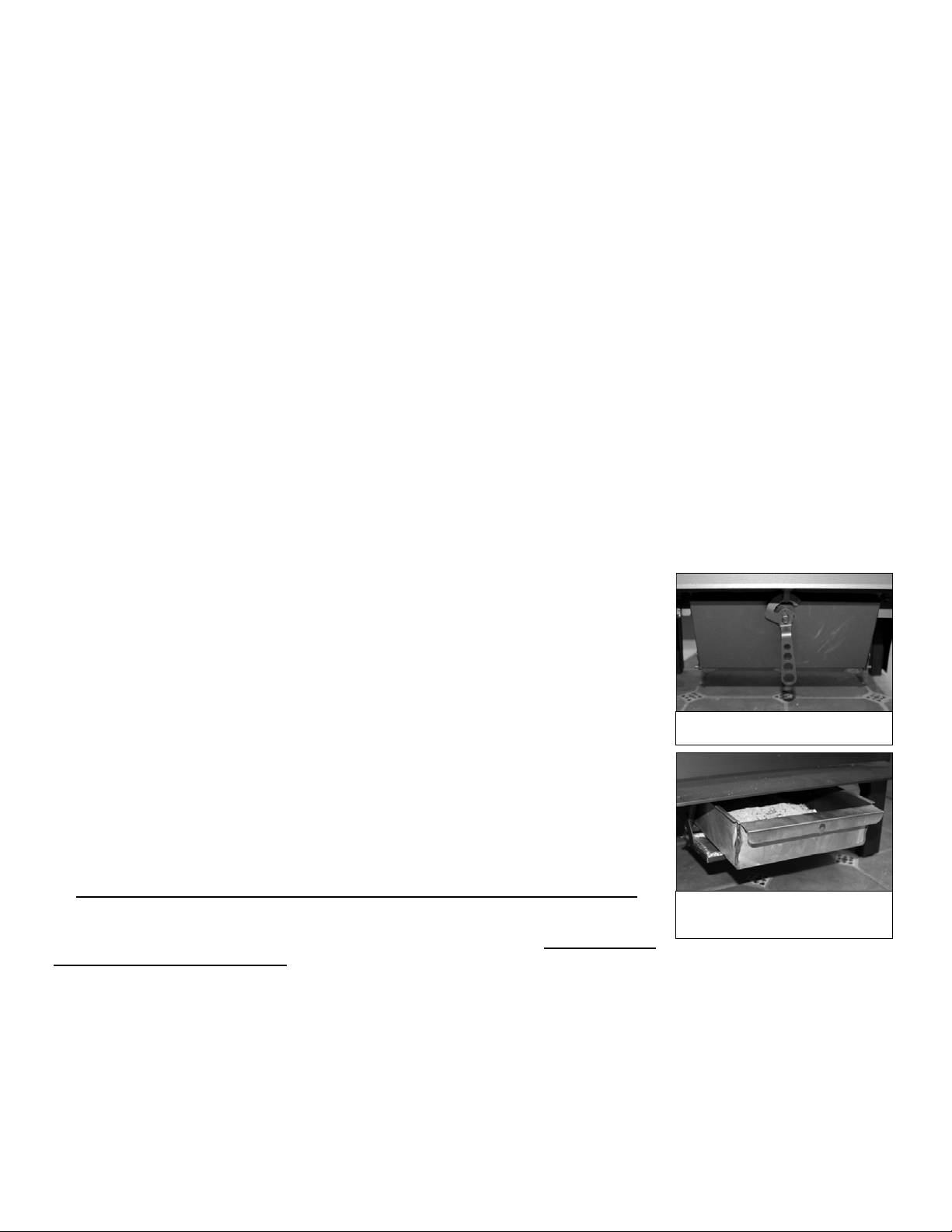
With an ash pan:
If your Ideal Steel is in continuous operation, you will probably need to empty the
ash pan every 7-10 days. You do not have to let the fire die out completely, but make
sure that it is reduced to hot coals. Open the catalytic bypass damper, and open the air
control damper. Remember to wear stove gloves - the ash pan will be hot! Open the ash
pan door located at the front of the stove, below the loading door. Carefully slide the lid
into place on the top of the ash pan and remove the ash pan from the base of the stove.
The lid slides over the long top edges of the ash pan. Close the ash pan door before
emptying the ashes into an appropriate container.
Do not open the ash removal door while the stove is in the middle of a long burn,
because the additional draft created under the fire could cause the stove to burn
excessively hot and the ash pan itself will be very hot, and full of live coals. If you are
burning your stove 24 hours/day, it is often easiest to empty the ashes first thing in the
morning, after an overnight burn.
Ashes should be emptied into a metal container with a tight fitting lid. The closed container of ashes should be
placed on a noncombustible floor or on the ground, well away from all combustible materials, pending final disposal. If
the ashes are disposed of by burial in soil or otherwise locally dispersed, they should be retained in the closed container
until all cinders have thoroughly cooled. Live cinders can take 36 hours or longer to cool.
Never shovel ashes into a combustible container like a cardboard box or a plastic bucket. Do not use a vacuum
cleaner to remove ashes unless it is specifically designed for woodstove ash removal. NEVER leave a container of
hot ashes on a wood floor, porch, or any combustible surface.
16
The ash Pan door is located at the
front of the stove, below the ash lip.
The ash pan door drops down and the
ash pan slides out from under the
stove for easy ash removal.
The Pipe Thermometer
We recommend placing the thermometer 8”-10”above the flue collar on single wall stove pipe if
the stove is vented out the top. If the stove is rear vented, the surface thermometer should be
placed on the steel plate toward the back of the stove.
If you are reading the single wall stove pipe temperature, the interior flue exhaust temperature is
about twice as hot. Since the 22 gauge sheet metal pipe is more reactive (faster heat transfer) than
the stove top, you will find you can engage the combustor sooner. We recommend engaging your
catalytic combustor once the pipe thermometer reaches 250° F.
Once the combustor is engaged, you should see the stove surface temperature rise and the pipe
temperature drop, indicating catalytic combustor activity. From a cold start it may take about 30
minutes to get the stove up to temperature. If you are reloading a hot stove, wait approximately 5-
15 minutes before engaging the combustor. The thermometer is not a precise instrument – it will
not tell you the exact temperature inside the firebox or in the flue.
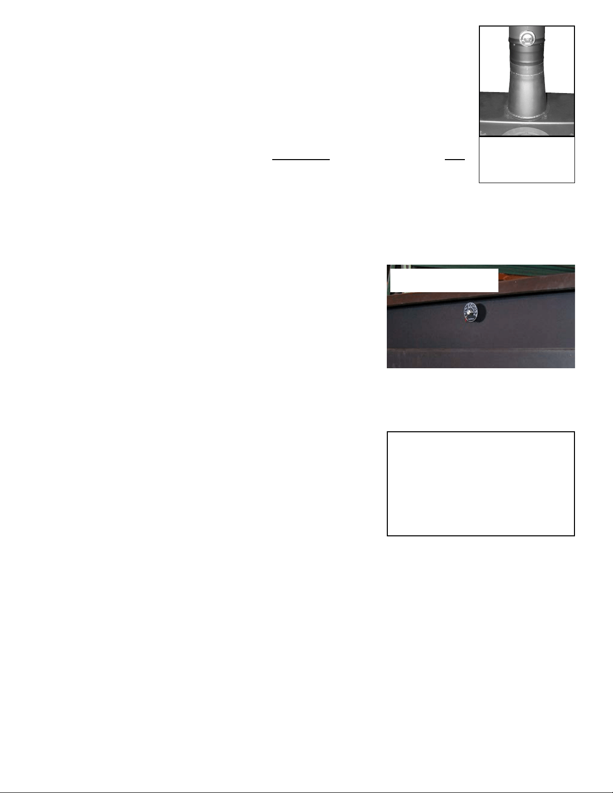
The Probe Thermometer
A probe thermometer is provided for measuring the temperature immediately downstream of the catalytic combustor.
This thermometer installs in a port right below the top lid of the stove, and
the sensing end of the probe extends to within 1 inch of the face of the
catalyst. The probe is calibrated from room temperature to 1700 degrees F.
The catalyst can be engaged as soon as the temperature on this probe exceeds
400 degrees F, or as soon as the temperature on the pipe thermometer exceeds
250 degrees (see above).
The best operating range for the catalyst is from 500 - 1400 degrees F. When
the temperature on the probe thermometert exceeds 1400
o
F, we recommend
closing the damper to prevent excessive heat from occuring
Overfiring
Burning a stove frequently at excessive temperatures is known as overfiring. When the surface temperature is
consistently over 700º F, the stove has reached 1400º F inside. Operation with temperatures in this range can lead to
metal warping, becoming brittle, and eventually deteriorating completely. It
can shorten the useful life of the catalytic combustor.
Avoid overfiring by letting the combustor and secondaries do most of the
work in the stove. Your stove is operating at peak efficiency when the
combustor is “engaged”and the secondaries are ignited, with the damper
lever set to a low to moderate setting, and the logs are glowing with
secondary flames apparent. You will get the greatest amount of heat per
pound of wood when the stove is operated in this manner.
Daily Use
Your Ideal Steel Hybrid stove is well suited for continuous firing on a 24 hour a day basis. It will burn for hours on
one load of wood, and will provide steady, even, heat for hours after the fire dies down. You need only disengage the
catalytic combustor when you kindle a fire, or reload the stove. Once the catalyst is ignited, it will continue to function
as long as there is smoke to burn.
Your connector pipe and chimney, or chimney pipe, should be inspected at regular intervals (not less than once every
two months). Examine the connector pipe for creosote, corrosion, loose seams, or excessive soot. Clean and replace as
necessary. The chimney or chimney pipe should be cleaned and checked by a certified specialist once a year. A small
mirror held at the cleanout door of a masonry chimney will be helpful. For a Class A prefabricated metal pipe, some
disassembly is usually required.
Smoke Flap
The Ideal Steel Hybrid is a front loading stove with a large loading door. In order to reduce the occurrence of smoke
spillage upon reloading, we’ve incorporated a drop down smoke flap. This flap proved to be essential in reducing smoke in
the home, especially for those who have a marginal chimney draft. Upon opening the loading door, the hinged smoke flap
17
DO NOT OVERFIRE!
AT TE M P TS T O AC H I EV E H EAT O U T-
PUT RATES THAT EXCEED STOVE
DESIGN SPECIFICATIONS CAN
RESULT IN PERMANENT DAMAGE
TO THE STOVE AND TO THE CAT-
ALYTIC COMBUSTOR.
Place the surface ther-
mometer 8” above t he
stove top for top vent, or
on the cover plate for
rear vent.
The probe thermometer is located
in the front of the stove, centered
under the top lid
will drop into a down position at the top of the door opening. When closing the
loading door, the smoke flap will be pushed back out of view. This flap can be locked
into an upright positon to keep it out of the way for loading, or it can be removed
from the stove, if you find this feature to be unecessary in your installation. To lock
the smoke flap in the upper position, simply take a hearth tool, like a poker, and push
it up and back. To release the smoke flap from the locked position, push up on the
latch located on the upper left side of the door opening (about 2” down), using a
hearth tool or the provided helping hand. Do not attempt to remove the flap while the
stove is hot.
The Helping Hand
The “helping hand”, which comes with your stove, can be used to operate the
door latch. Simply insert the bent finger into the door handle circle to use to safely
open/close the loading door. The loading door and the door handle are very hot,
so use the tool provided. The “helping hand” conforms to UL requirements and is
made so that if you let go of it, it will “fall-away” from the stove and not become too
hot to handle.
The Cook Top
The top lid of the Ideal Steel Hybrid woodstove consists of a three-piece
decorative metal set. The lid has been designed to enhance the beauty and versatility
of your stove. The cook top has three distinct areas that provide high, medium, and
low temperature zones for more cooking flexibility. The center “burner” can be
removed to expose a stainless steel surface which delivers the highest heat. The left
and right burners are elevated about 1/8” and the center burner is elevated 1/4” .
The steel cook top is not designed as a cooking surface and food should always be
placed in a heavy duty Dutch oven or skillet, not directly onto the steel surface. The
decorative metal set can be easily removed and the steel cook top/lid will stand
upright to access the catalytic combustor below. This easy access makes cleaning and
replacing the combustor very user friendly.
Firewood
Your Woodstock Soapstone Stove is designed to burn dry, natural cordwood. Higher efficiency and lower emissions
generally result when burning air dried hardwoods, as compared to green, freshly cut hard woods. It is perfectly fine to
burn soft woods in your stove as long as they are properly dried. Hardwoods are preferable because they are typically
denser than soft woods which gives them a higher fuel value per volume.
The moisture content of some trees may range as high as 50% – i.e., there is as much moisture in the tree as there is
wood. After wood has been cut to length, split and stacked for a year, the moisture content will usually range from 15-
25%. Splitting wood before it is stored will reduce drying time. Properly dried wood will produce more heat, reduce the
likelihood of water vapor condensing in the chimney, forming creosote, and result in less pollution entering the air. It is
safer and more efficient to burn dry hardwood than green or wet wood that smolders.
The advantages of burning dry wood are many. Dry wood is lighter, easier to split, and easier to carry. It is easier to
light, produces more heat, and generates less pollution. If you burn wet wood much of the energy generated by the fire
is used to drive moisture out of the wood, rather than producing heat for you. Dry wood will maintain the highest
combustor temperatures and burn the most efficiently. Creosote is much less likely to form
if you burn dry wood.
DO NOT BURN TREATED OR PAINTED WOOD, COAL, GARBAGE,
CARDBOARD, SOLVENTS, COLORED PAPER, OR TRASH IN YOUR WOODSTOCK
SOAPSTONE STOVE. Coal and artificial logs burn much hotter than wood and could
cause damage through overheating the the steel or the soapstone panels. Burning treated
wood, garbage, solvents, colored paper or trash may result in the release of toxic fumes and
may poison or otherwise render the catalytic combustor ineffective.
Burning cardboard, loose paper, and trash will add significantly to ash and soot buildup,
and it will not produce much heat. Fly ash from improper fuel can also coat or plug the
combustor, causing smoke spillage into the room. Under normal operating conditions, the
Woodstock Soapstone Stove is designed to last for generations. It is not, however, designed
for continuous over-firing, or firing with coal, artificial logs or trash.
DO NOT BURN
• Treated Wood
• Coal
• Garbage
• Cardboard
• Solvents
• Colored Paper
• Trash
18
Removable Center Burner
Helping Hand
High heat for fast
sautéing or wok
Smoke Flap
Smoke flap drops down to help prevent smoke
spillage.
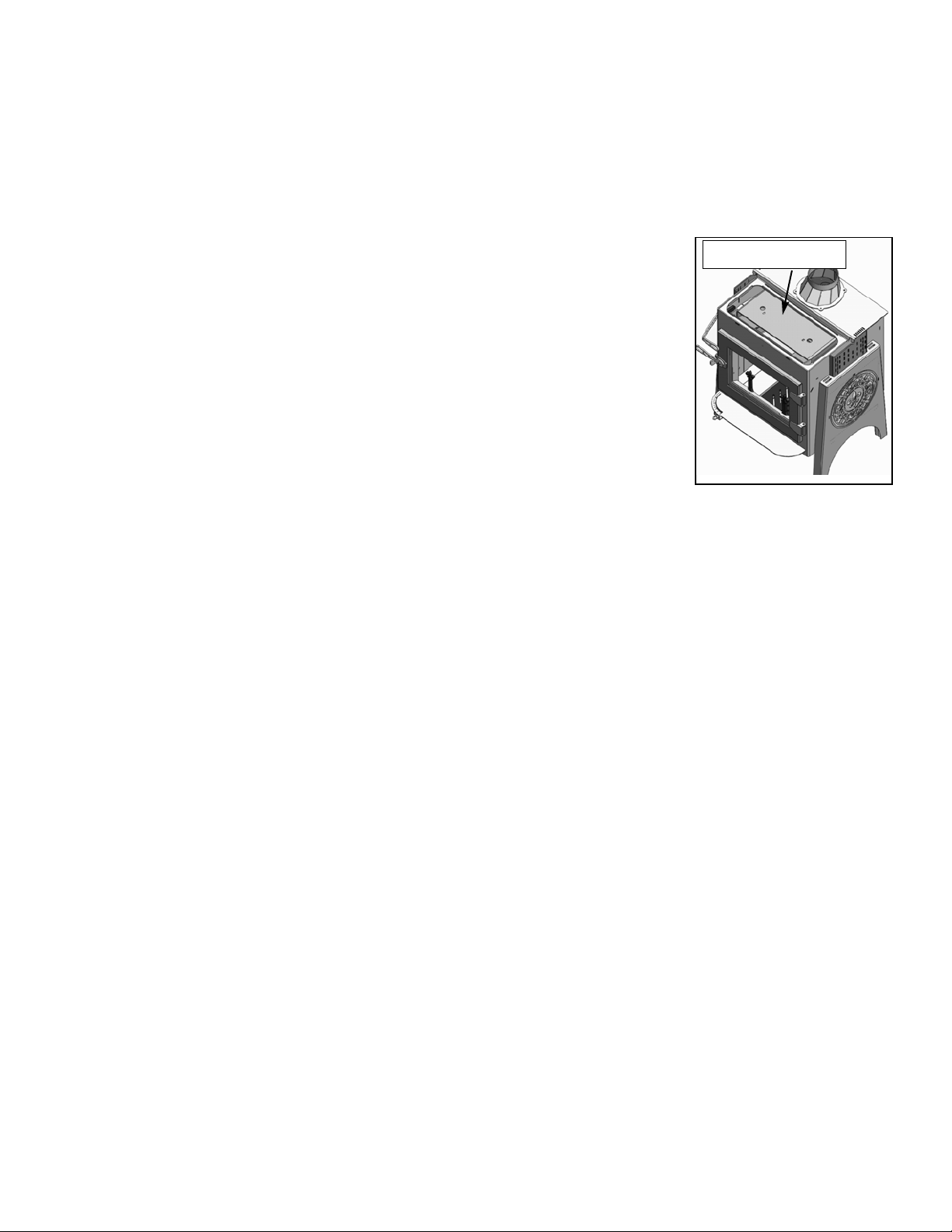
THE CATALYTIC COMBUSTOR
Here is how your catalytic combustor works.
The catalytic combustor is a stainless steel honeycomb with hundreds of cells. If you looked at the inside of each cell
with a microscope, you would see that the walls are uneven and filled with minute nooks and crannies. Precious metals,
such as platinum, are sprayed on the inside of these cells to coat all of the nooks and crannies. This creates the largest
possible surface area to interact with the wood smoke. The catalytic combustor in your stove is very similar to the one in
the exhaust system of your automobile and works to achieve the same results - high efficiency and clean air!
When you first start a fire, you should bypass your catalytic combustor and let the
smoke go directly up the chimney. Once wood smoke reaches 500º F (about 10-15 minutes
after restablishing a strong fire), it is hot enough to ignite the catalytic combustor. As the
wood smoke passes through the cells in the combustor, the smoke reacts with the precious
metals which line the inside of the honeycomb and both combustible gases and particles in
the smoke ignite and burn. This “catalytic burn” reduces emissions and also increases heat
output from the stove.
Without a catalytic combustor, between 5% - 40% of the chemical energy contained in
wood simply escapes up the chimney when wood is burned. Energy laden gases are
exhausted up the chimney where they pollute the air or may condense on the inside of the
chimney flue as creosote. The slower the burn, without a catalytic combustor, the greater
the amount of energy that is lost. A long smoldering fire is the least efficient use of energy
in wood, yet it produces lots of smoke, which is the fuel supply for the catalytic combustor.
Most of the chemical compounds in wood smoke are combustible. The catalyst produces high temperatures, which
loosen the bonds of these chemical compounds and “burns” wood smoke. A stove that “burns” these compounds and
uses smoke as additional fuel will burn more efficiently and produce more heat, while reducing creosote and air
pollution at the same time. However, most stoves cannot consistently produce temperatures high enough to burn
cleanly, particularly during long burning times - hence the need for a catalytic combustor.
Your catalytic combustor can get the most efficiency out of every piece of wood if it has three things: temperature,
turbulence, and time.
1. Temperature. The catalytic combustor can only start burning the gases in the wood smoke after the smoke has reached
at least 500 degrees F. Before the smoke reaches that temperature, it simply is not hot enough to start the reaction at
the combustor. This will result in an inefficient smoldering fire.
2. Turbulence. The wood smoke can interact best with the precious metals inside the honeycomb cells if there is some
variation in the air flow. Increased turbulence enables more of the wood smoke to come into contact with more of the
nooks and crannies in the honeycomb cells. The exhaust path as well as the irregular surface of the combuster cells
adds needed turbulence.
3. Time. Once the temperature and turbulence are achieved, the catalytic combustor just needs to have enough time to
burn all the gases in the wood smoke. For this reason, it is best to minimize the amount of air you allow into the
firebox once the combustor is ignited. Allowing too much air into the firebox speeds up the rate at which the fire
burns and allows more wood smoke to be consumed by the secondary combustion system . The ideal air setting for a
long catalytic burn allows enough air to keep the wood burning and producing smoke.
With proper care, a new catalytic combustor will give years of fuel savings and lowered emissions. By following
some simple guidelines you can ensure maximum combustor performance and longevity. Your catalytic combustor is
designed to last for 12,000 -14,000 hours of use. You can ensure yourself of getting the maximum life from your
combustor by following these simple guidelines:
1) Burn only natural, dry wood.
2) Wait until the exhaust gases reach about 500 degrees F before engaging the catalytic combustor (about 5-15
minutes, or 250° on single wall stove pipe, after establishing a strong fire).
3) Bypass the combustor before reloading, and leave the bypass open for a few minutes after reloading, to raise
the temperature in the stove.
4) Don’t overfire the stove.
5) Clean the combustor regularly. See instructions below.
You can also obtain a lot of useful information by visiting our website (www.woodstove.com). Other very useful web
19
Simple radiator installed
above catalyst
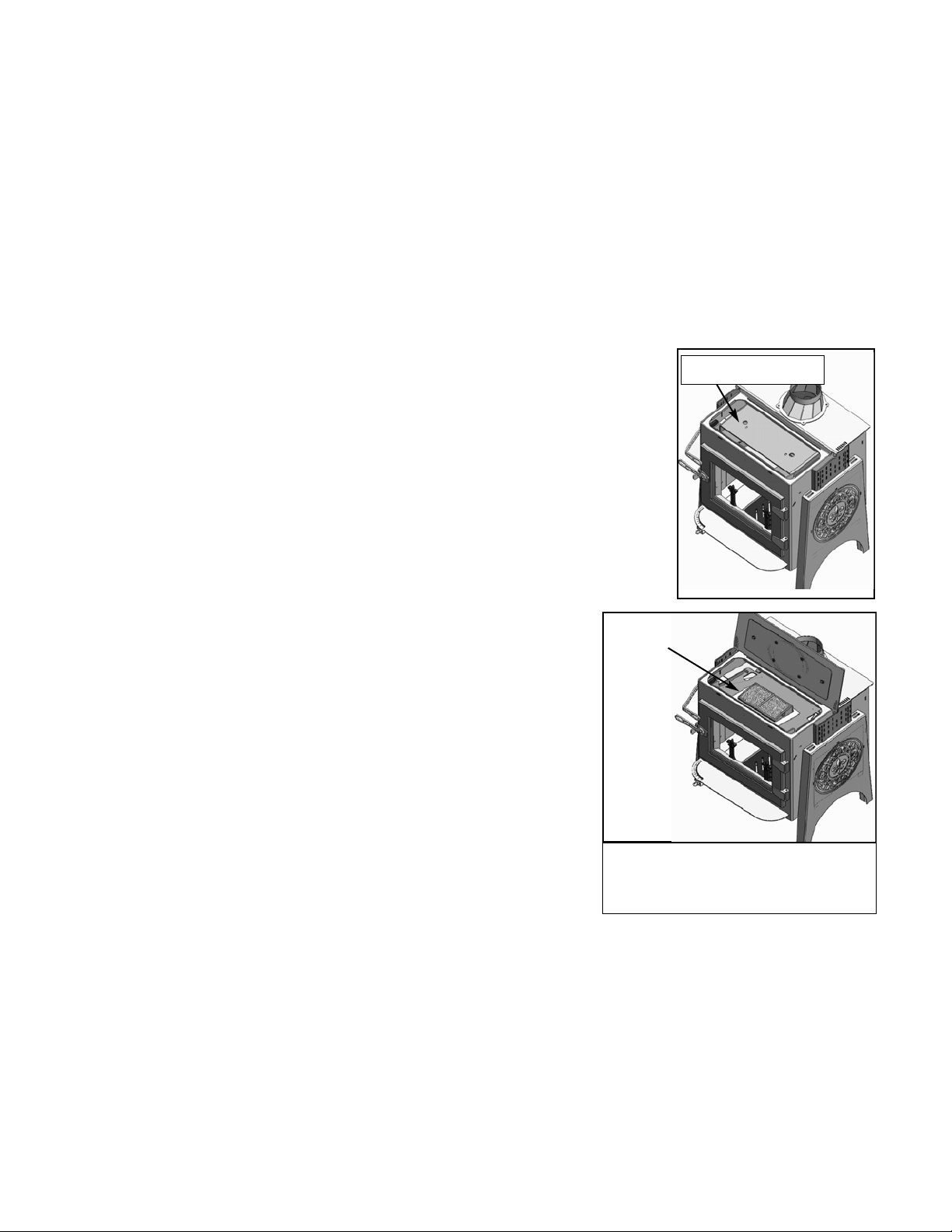
sites on all aspects of wood burning are (www.hearth.com), (www.woodheat.org) and (www.csia.org). CSIA is the
Chimney Safety Institute of America.
Inspection & Cleaning
Your stove comes with a new stainless steel combustor already installed. The stainless combustor is a honeycomb foil
block located under the top lid of the Ideal Steel . Typical lifespan for a well maintained catalytic combustor is 4-6 years.
There are a few ways to determine if your combustor needs to be cleaned. If you notice the smoke exiting your chimney
is thicker and darker in color, the combustor may need cleaning. Additionally, if you notice reduced draft or backpuffing,
or performance and heat output has diminished, then the combustor may not be working as efficiently as designed.
Plan to clean and inspect your catalytic combustor about every 4-6 weeks. Any fly ash deposits on the combustor will
need to be brushed or vacuumed off. An accumulation of fly ash can reduce the draft, causing backpuffing, sluggish
burning, and inefficient heating performance. You should clean and check your combustor before the heating season
begins, as well as on a regular 4-6 week basis.
COMBUSTOR CLEANING HOW TO:
Tools needed: (1) work gloves and safety glasses; (2) soft bristled paint brush or vacuum
cleaner (preferably one designed for ash removal).
1. Be sure the fire is out and the stove is cold. If you are using a regular home vacuum, it
is extremely important that no hot ashes or embers be sucked into it as this could result
in damage to the vacuum or cause a serious fire. Remove the center burner, if equipped,
from the stove. Open the top lid. The combustor is located under the radiator. Lift the
radiator up and remove it from the stove.
2. Lift the combustor out of the stove. Brush or vacuum the combustor thoroughly, from
both sides. Do not use high pressure compressed air to clean the combustor, as this could
damage the reactive coating. Be sure to remove all fly ash from the combustor. Inspect
the gasket that the combustor housing rests against.
3. Return the combustor to the stove. Be sure that it is seated properly. Place the radiator
over the combustor. Raise and lower the bypass lever to be sure the radiator is
seated properly.
4. Close the top lid and return the center burner to the top of the stove.
NOTE: A more thorough cleaning can be done as needed, by following the
same directions above. After the combustor is vacuumed or brushed off, rinse
(or soak for 10-15 minutes) the combustor with a mixture of 50% white vinegar
& 50% distilled water. After rinsing or soaking in the 50/50 mixture, rinse with
distilled water. Allow the combustor to dry before reinstalling in the stove.
Catalytic Combustor Replacement
If you feel that your catalytic combustor is not working properly, please
contact Woodstock Soapstone Company at 1-800-866-4344 for instructions
regarding return and replacement. Accessing the catalyst in your new Ideal
Steel Hybrid Woodstove is simple. Just lift the top stove lid. Then remove the
radiator (pictured above right) using the two finger holes in the top. You can
lift the catalyst plate from the stove.
.
Frequently Asked Questions
Q. How does the catalytic combustor work?
A. The catalytic combustor breaks the bonds that hold the chemicals contained in wood smoke together. The result is
that these chemicals begin to burn at temperatures of about 500 degrees F (the normal range of exhaust gas
temperatures). Without the catalytic combustor, wood smoke would have to be brought up to a temperature of 1000
to 1200 degrees F in order to start to burn. A stove with a catalytic combustor will generate up to 25% more heat from
each piece of wood, thus reducing the amount of fuel used during the year.
There are three advantages to burning the smoke created by burning wood. First, the smoke becomes another source of
20
The Catalytic Combustor is easily accessible. Just
lift the lid, remove the radiator using the two fin-
ger holes, and the catalyst is visible. The catalyst
can be removed by lifting the catalyst housing.
Simple radiator installed
above catalyst

fuel, giving you more heat from the same amount of wood. Second, creosote causing materials will be burned up instead
of being deposited in your chimney, reducing the risk of a chimney fire. Third, air pollution will be drastically reduced.
Q. How can I tell if the catalytic combustor is working or “worn out”?
A. First - The best way to tell if the catalytic combustor is working is by observing the smoke coming out of your
chimney. If there is only a small amount of smoke, and/or it’s white in color, the catalytic combustor is working.
You will see significantly more smoke when the combustor is being bypassed than when the smoke is being burned
by the combustor.
Second - One very noticeable effect of a well functioning combustor is the high efficiency of your stove. Catalytic
combustors produce lots of heat, which the stove radiates into your home. If you notice that the stove is producing
less heat, or that a load of wood doesn’t provide as much warmth, under similar circumstances, as it did before, it’s
time to check the combustor. If and when the catalyst ceases to function properly, the stove will produce noticeably
less heat.
Third - Regular inspection of the connector pipe and chimney flue should show very little accumulation of soot and
creosote. Soot is typically brown and powdery when the combustor is working properly. Heavy buildup of black
sticky creosote may indicate the combustor is not functioning or needs cleaning.
If you suspect that your catalyst is not working, let the stove cool down and clean the combustor and try it again.
Q. How do I maintain my catalytic combustor?
A. Combustors should be inspected and cleaned if necessary every 4-6 weeks during the heating season. When the
stove is cool, the combustor can be cleaned by thoroughly vacuuming or brushing both sides.
If the stove does not draft well when the catalytic combustor is engaged then the combustor cells themselves might be
partially plugged with fly ash. If this is the case, follow the cleaning procedure described in detail on page 20 of this
manual.
Q. Is it all right to burn my stove hot daily to clean any build up in my chimney system?
A. It is not necessary to burn your stove hot daily to burn off any creosote build up in the chimney. This function is
performed by the catalytic combustor. It is there to reduce the emissions from the stove that contribute to deposits in
the connector pipe and chimney flue.
View more frequently asked questions and articles at our web site www.woodstove.com. Other very useful websites
on all aspects of wood burning are www.hearth.com, www.woodheat.org, and www.csia.org. CSIA is the Chimney
Safety Institute of America.
TWO OTHER IMPORTANT POINTS REGARDING CATALYTIC COMBUSTORS:
1) The combustor uses wood smoke as fuel. Most smoke is created in the early stages of the burn cycle. When a bed of
coals is all that remains of your wood, there is little smoke left to fuel the combustor, and it will no longer create
substantial amounts of heat. Hence, the temperatures on the surface thermometer tend to fall toward the end of the
burn, even though the firebox is full of hot coals. This does not mean that you have to reload the stove or open the
bypass. Let the hot coals burn down to ashes.
2) Since the combustor blocks the path of exiting smoke, it can reduce the draft in your stove. When draft is reduced by
warm or rainy weather, open the bypass damper longer when starting the stove to create more draft.
CATALYTIC COMBUSTOR WARRANTY
The catalytic combustor in your Ideal Steel Hybrid Woodstove is fully warranted for three years from the date of purchase
against any defect in workmanship or materials that prevent the combustor from functioning when installed and operated
properly. The catalytic combustor is additionally warranted for three years from the date of purchase for any deteriora-
tion in the stainless steel substrate material. For instructions regarding return or replacement of the catalytic combustor,
please contact:
Woodstock Soapstone Company, Inc.
66 Airpark Road
West Lebanon, NH 03784
Phone: 1-800-866-4344 • Web: www.woodstove.com
21

MAINTENANCE
Stove Cleaning
The steel body of your Ideal Steel Hybrid stove is painted with two coats of high temperature stove paint. Under
normal operating conditions, this paint will not peel or blister. We suggest cleaning by dusting with a soft brush or
cloth, or vacuuming with a brush attachment when the stove is cold. If the steel is exposed to moisture for a long period
of time it may develop surface rust. If this happens, brush the affected area until clean with either a short wire brush or
medium steel wool and then touch-up with high temperature stove paint, which is available from Woodstock Soapstone
Company.
The soapstone that lines the firebox interior is rugged and well suited to the harsh environment of the firebox. It
should last for years under normal use. Should you need a replacement soapstone part, contact Woodstock Soapstone
Company directly.
Glass Cleaning
We use ceramic glass in our stoves because it is resistant to both impact and thermal shock. The panes of ceramic
glass installed in the stove fronts have full gaskets around the perimeter so there is no contact between the glass and the
steel frame.
There are two panes of glass at the front of each stove, with an air-space between the two panes. This “thermalpane”
arrangement helps keep the temperature on the inside of the glass higher and prevents condensation and soot from
accumulating. The Ideal Steel Hybrid has a large glass area with an “airwash” design in which the primary air supply
washes over the front glass to assist in keeping the glass free of ash and soot.
The glass may soot up the first time you use the stove (from condensation already inside the stove). Don’t be alarmed!
Usually, as soon as you build up adequate temperature with a hot fire, the glass will clean itself. The residue will burn
off, and it will stay clean. Soot accumulation on the inside of the glass is more likely in the spring and fall, when
temperatures are very mild and you are less likely to maintain a hot fire.
To clean the inside of the glass or wipe off fly ash, we recommend that you use a brush with soft bristles (like a
paintbrush). A white vinegar and water solution works well to remove most ash or soot accumulation. You may clean
heavy soot from the glass with very fine steel wool (0000 grade), but first, be sure the fire is out; and second, be sure that
the glass has cooled to room temperature before you clean it. DO NOT ATTEMPT TO CLEAN HOT GLASS.
Gasket Replacement
There are 4 places on your stove where you should check the gasket routinely: (1) on the loading door, (2) under the
steel lid/ cooktop, (3) under the catalytic bypass damper, and (4) the ashpan door (models purchased with the ashpan).
These gaskets are most important for maintaining high efficiency and clean burning. Close a slip of paper in these
gasketed areas. There should be resistance as you pull the paper out. If there is any evidence of deterioration and/or
leaking in any of these areas or if any of the gasket material in the stove becomes worn or frayed, it should be replaced.
Please contact Woodstock Soapstone Company for replacement gasket and instructions. The sizes of all the gaskets on
your Ideal Steel Hybrid woodstove are included in the parts list on page 28 of this manual.
Routine Checks And End of Season Maintenance
Every few weeks of operation we recommend checking the chimney connector (stovepipe) and combustor (see
combustor section) and cleaning, if necessary. The connector pipe and chimney should be inspected every two months at
a minimum and cleaned if necessary.
When the weather warms up and the burning season is over, it is a good idea to do a thorough spring cleaning and
inspection of your stove and chimney system. We recommend an annual inspection and cleaning by a certified chimney
sweep who has the tools and knowledge to inspect the whole system, from top to bottom. Chimney safety is an
important part of responsible wood burning . The best way to gain confidence in the safety of your Ideal Steel Hybrid
woodstove is to have it serviced and inspected once a year by a professional chimney sweep. The Chimney Safety
Institute of America maintains a database of certified sweeps nationwide. Go to their website www.csia.org to find a
22

professional in your area.
If you live in a climate with warm, humid summer weather, your stove may collect moisture from warm, moist,
chimney downdrafts during the summer. If this happens, you may get smoky smells in your home. One way to reduce
the likelihood of this happening is to block the flue exit in the stove with fiberglass insulation at the end of the heating
season. This will help prevent downdrafts and humidity from entering the stove. (You’ll have to be careful to remember
to remove the insulation before you light the stove again in the fall!). Some prefer to place a tray of kitty litter or baking
soda in the firebox to reduce moisture and odors.
Creosote Formation and Need for Removal
When wood is burned too slowly, it produces tar and other organic vapors, which combine with expelled moisture to
form creosote. The creosote vapors condense in the relatively cool chimney flue of a slow burning fire. As a result,
creosote residue accumulates on the flue lining. When ignited, this creosote makes an extremely hot and dangerous fire.
The chimney connector and chimney should be inspected at least once every two months during the heating season to
determine if creosote buildup has occurred. If creosote has accumulated it should be removed to reduce the risk of a
chimney fire. Cleaning the combustor regularly will also greatly reduce creosote buildup. Under certain conditions,
creosote can form rapidly.
The most likely conditions for creosote to occur are: (1) when a large number of small pieces of wood are added to a
hot bed of coals and the damper is then completely closed; (2) extremely long, smoldering fires, and; (3) burning wet or
green wood.
Lack of combustion air and smoldering fires usually result in dense smoke and low stack temperatures in the
chimney connector and the chimney. Wet or green wood can also produce dense smoke and excessive water vapor,
which can quickly lead to creosote buildup.
Creosote will accumulate faster in exterior chimneys than interior chimneys because of colder outside temperatures.
There are three stages of creosote build-up. The first is a flaky, crystal like accumulation which can be removed with a
brush. The second is a tar like coating. The third is a hard, glossy enamel like coating that is difficult to penetrate. If
your chimney is heavily coated with tar or enamel like creosote, we recommend that you consult with an experienced
chimney sweep about removal and prevention.
CREOSOTE PREVENTION: Without question, the best way to treat creosote is to prevent its accumulation. In order to
reduce the danger of accumulation, we recommend the following:
1. Burn only properly dried firewood. Dry wood burns hotter, cleaner, and expels less moisture to condense.
2. Use the catalytic combustor properly. It can reduce possible creosote accumulation by as much as 90% and
improve stove efficiency at the same time. Be sure to read the section on catalytic combustors on pages 18-21.
3. Never operate your stove for extended periods of time with the draft control completely closed. Both the wood
fire and the catalytic combustor need oxygen to burn efficiently.
4. Re-establish a hot fire, and reignite the combustor after every reloading by opening the primary air control for
about 10 minutes.
5. Check the catalytic combustor output. Use the thermometer provided with the stove to be sure that the catalytic
combustor is igniting properly when you kindle a fire or reload the stove. The temperatures on the stove top
should rise noticeably when the catalytic combustor is engaged.
6. Avoid long, smoldering fires. Again, the catalytic combustor is critical here. Hot firebox temperatures (with the
stove top thermometer in the 400-600
0
F range) will produce more complete combustion and maintain proper
catalytic activity.
23

TROUBLESHOOTING GUIDE
Problem
Stove smokes
Back Puffing or
sudden internal
ignitions
Combustor not
glowing
Stove burning too
hot or fast
Possible Cause
Operating technique
Cold start
Blocked Chimney
Blocked outside airduct
Oversized chimney
Chimney too short
More than one appliance vented
into flue
Operating technique
Burn rate too low
Chimney down draft
Combustor is plugged
Tight house
Late stage of burn
Ashpan Door is Open
Excessive draft
Extra tall chimney
Solutions
Open bypass and air damper prior to reloading stove
Check and establish a chimney draft prior to lighting the
stove. If you have neutral or a down draft, preheat the
chimney with a hairdryer, heat gun, or twists of lit newspa-
per.
Examine chimney and stovepipe for blockage and creosote
accumulations. Check spark arrestor screen on your cap, if
you have one.
Check the outside inlet for blockage caused by snow,
debris, or insects.
Reline chimney to appropriate size.
Add height (industry standard is 15ft or more).
Disconnect other appliances, seal openings appropriately.
Open bypass and air dampers before opening to reload and
keep it open a few minutes after reloading.
Open air damper to allow for hotter burn.
In high wind areas, a specially designed wind cap may be
necessary.
Clean combustor of accumulated fly ash.
Dedicated air supply with outside air adapter attachment to
stove.
Combustor does not need to be glowing to be working.
Check smoke exiting chimney to help determine if combus-
tor is working properly.
Close ash door securely, check ash door gasket for tight
seal.
Adjust air damper to lower setting;a pipe damper may be
necessary.
Consider installing pipe damper
24

Stove burning too hot
or fast (cont.)
Insufficient Heat
Acrid odor during
initial burn
Window Dirty
High wind or hilltop location
Poor quality or green wood
Blocked outside air duct
Heat going up chimney
Paint and/or window gasket
curing
First start up fire
Airflow too restricted
Smoldering fire
Install wind cap on top of chimney
Use only dry wood (dried at least one year
depending on wood species)
Test with kiln dried wood.
Check outside air duct for blockage
Test with thermometer on 1st section of
stovepipe– temps should drop below 300 degrees
F when combustor is engaged.
Open windows until paint or gasket is cured.
This is sometimes the result of condensation in a
new stove, and should disappear after several
hot fires.
Open the air damper in small increments until
some slow flames appear. Run a hot fire to burn
smoke off the glass, or remove build up with
glass cleaner when stove is cold.
Green or wet wood. Burn dry wood, or open air
damper slightly for a hotter burn. (see above)
Is my Combustor still working?
Your catalytic combustor is viable for 12,000 to 14,000 burn hours. This translates, roughly, into a life span of 4 -6 years.
If the catalytic coating is not working as it should, it is not burning the gas vapors in the smoke and therefore, the smoke
exiting your chimney will be darker in color. If your draft is sluggish and you have ruled out any draft related issues in
the venting or in the wood supply, your combustor may not be burning the smoke vapors and too much volume is try-
ing to pass through the honeycomb at one time. If heat output is diminished, and any other factors are ruled out, that
may also be a sign that the catalytic combustor is not burning the smoke vapors, therefore not extracting maximum heat
from available BTUs in the wood you are burning.
25

SAFETY
Overview
To gain maximum enjoyment and benefit from your stove, you must have a safe installation. Adhere to all guidelines
found in this manual. All local and national building codes need to be followed. Having a certified installer perform all
connections to an inspected chimney system is strongly advised. If you choose to perform any or all of this work your-
self, it must be inspected by either a Certified Wood Stove Specialist or a Certified Chimney Specialist.
You will often find the local Fire Department to be very knowledgeable. They may inspect your house for proper
warning devices, fire extinquishers, and evacuation routes. Keep their phone number handy. Although many communi-
ties utilize Fire Department personnel for woodstove installation inspections, they are not usually trained as combustion
venting specialists. Generally, you are best advised to use a certified specialist. The sense of security that comes with a
properly installed and maintained system is worth far more than its cost.
Installation
Your Woodstock Soapstone Stove has been thoroughly tested and listed to UL #1482 by an independent testing labo-
ratory. UL #1482 is the standard for testing solid fuel appliances and is universally recognized by all national building
regulatory agencies, (SBCC, BOCA, ICBO) and individual states. Your woodstove is a safe product, but it must be
installed in accordance with the instructions in this manual. Woodstoves themselves rarely cause fires, but improper
installation or careless operation are often to blame.
Follow the guidelines in the Installation chapter of this manual with regard to:
• Proper chimney and connector pipe
• Clearances to combustible surfaces and objects
• Floor protection
Smoke and the Chimney
According to www.woodheat.org, “The chimney is the engine that drives a wood heat system”. To have a safe system
you must have:
• The correct type of chimney
• The correct size of chimney
• Correct location inside the house
• A properly installed system
Smoke spilling into the living space when starting a fire is an inconvenience. Smoke spilling into the house when you
are away or asleep can be a major problem. In order to have all the smoke go up the chimney all the time, the chimney
must have positive draft. Ideally, this draft is between 10-18 pascals, or .04-.07 inches water column, a pressure measure-
ment, when there is no fire in the stove. A certified installer can perform a simple draft test for this.
Hot Surfaces
Your stove is HOT to the touch! Utilizing the “helping hand” and use of heat resistant or insulated stove gloves can
prevent serious burns when opening or closing the door, ash pan, or lid of your stove.
Ash removal
Convenient and safe ash removal is a necessity for trouble free wood burning. An ash removal container should have:
•A comfortably large capacity
•Good stability
•A top that closes securely and will not fall off
•Legs or other means of preventing downward heat flow
•A design that prevents spilling when loading
Ashes should never be dumped into a combustible container, such as a cardboard box, and an ash container should
never be set on a combustible surface. Hot embers in the ashes can often stay viable for 36 hours or longer after removal
from your stove.
26

Precautions
•Smoke detectors: A smoke detector is inexpensive insurance and is required by most localities. They can either work
on batteries, or can be hard-wired into your electrical system. If you have battery operated detectors, it is a good idea
to replace batteries on an annual basis (i.e.: every New Year’s day, or 4th of July, etc). They will sound an audible
alarm in the event of the presence of smoke. Smoke will almost always precede a wood fueled fire.
•Fire Extinguisher: If you burn wood, you should have at least one ABC dry chemical extinguisher. The chemical
extinguisher is preferable to water because the application of cold water to hot metal stove pipes can cause metal
parts to buckle or crack, thereby releasing more fuel to the fire.
•Carbon Monoxide Detector: These operate in a manner similar to smoke detectors but are usually user calibrated
and record minute quantities on a digital readout before sounding an audible alarm. The chances of carbon monoxide
being created and escaping from your properly installed and operated stove are miniscule. You may have other vent
ed appliances in your home that could be potential problems. The investment in a high quality carbon monoxide
detector is well worth its cost in the peace of mind it affords.
•Chimney inspection: Your connector pipe and chimney, or chimney pipe, should be inspected at regular intervals.
Examine the connector pipe for creosote, corrosion, loose seams, or excessive soot. Clean and replace as necessary. The
chimney, or chimney pipe, should be cleaned and checked by a certified specialist once a year. A small mirror held at
the cleanout door of a masonry chimney will be helpful. For a Class A prefabricated metal pipe, some disassembly is
usually required.
Emergency Procedures In The Event of a Chimney Fire:
If you have a chimney fire or runaway fire, follow these safety precautions:
1. Close the draft damper immediately, with a slow and even motion. This cuts off the supply of oxygen to the stove.
2. Call the fire department immediately.
3. Get everyone out of the house. One adult should stay in the house to check for sparks and signs of fire. Those out-
side should watch the roof for signs of fire.
4. If there is a danger of a fire, discharge the fire extinguisher into the stove. Do not pour or spray water directly into
the chimney as rapid contraction caused by the application of cold water could cause the tile liner in the chimney to
crack.
5. After the fire is out, check the stove, chimney connector and chimney carefully for signs of damage. The entire sys-
tem should be thoroughly inspected by a certified chimney professional.
Note: Chimney fires must be put out from the bottom. The entire system must be air tight to suffocate a fire; hence the
importance of having a tight cover on the chimney cleanout and not venting two appliances into a single flue.
The length of time it takes to bring a chimney fire under control depends on the amount of fuel in the stove, the rate at
which it is burning and the amount of oxygen available to it. The faster it is brought under control the less severe any
damage is likely to be.
27
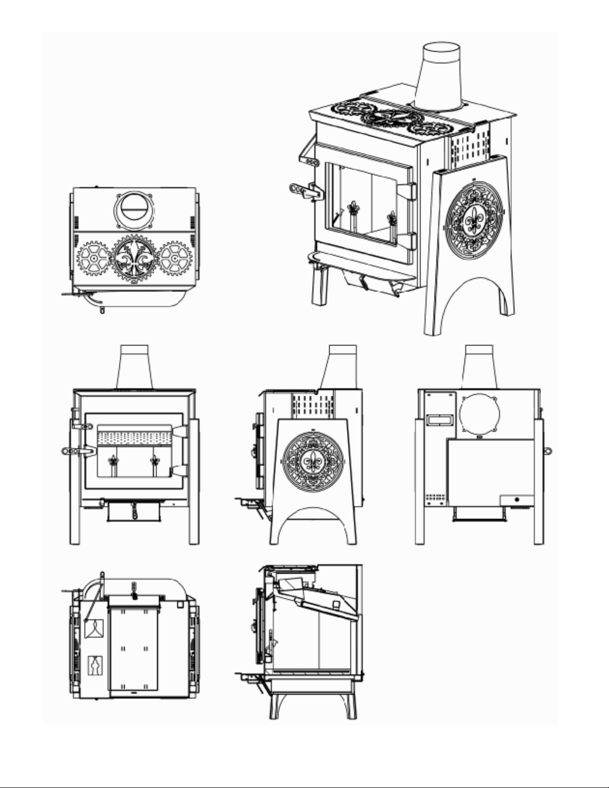
MODEL 210 VIEWS
Top Vie w
Front View
Side View
Back View
Bottom View
Cut-Away
MODEL 210: IDEAL STEEL HYBRID
28
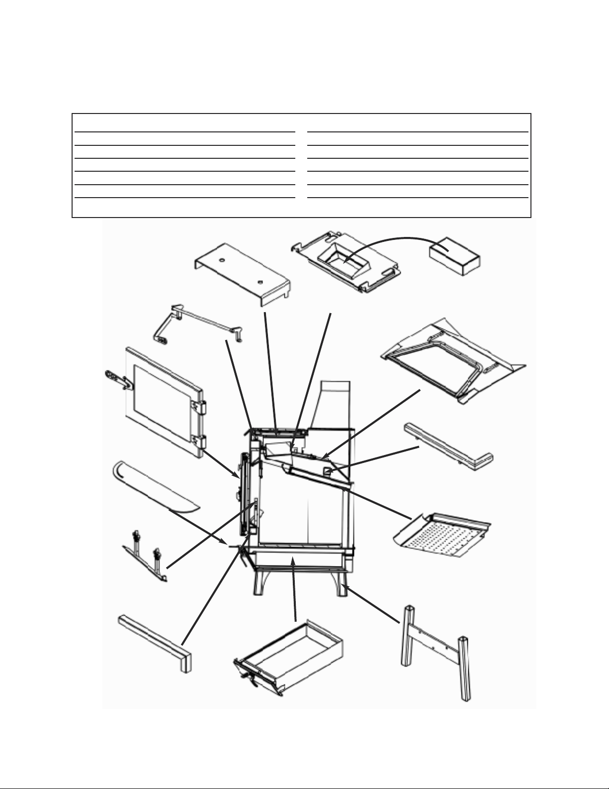
PG-18
Andiron Assembly
PG-930 Air Jet
Tube Assembly
PG-16
Ash Pan Assembly
PG-915
Tertiary Air Tube
PG-12
Fireback Assembly
PG-14
Leg “H” Weldment
PG-16
Upper Baffle Assembly
K-535
Catalyst
PG-19
Sled Assembly
PG-918
Radiator
PG-22 Bypass Rod
Assembly
PG-11
Door Assembly
PG-121 Ash Lip
Sub-Assembly
PG-918 Radiator
PG-22 Bypass Rod Assembly
PG-11 Door Assembly
PG-121 Ash Lip Sub-Assembly
PG-18 Andiron Assembly
PG-930 Air Jet Tube Assembly
PG-16 Ash Pan Assembly
PG-19 Sled Assembly
K-535 Catalyst
PG-16 Upper Baffle Assembly
PG-915 Tertiary Air Tube
PG-12 Fireback Assembly
PG-14 Leg “H” Weldment (2)
MODEL 210 ASSEMBLIES, PAGE 1
MODEL 210: IDEAL STEEL HYBRID
29
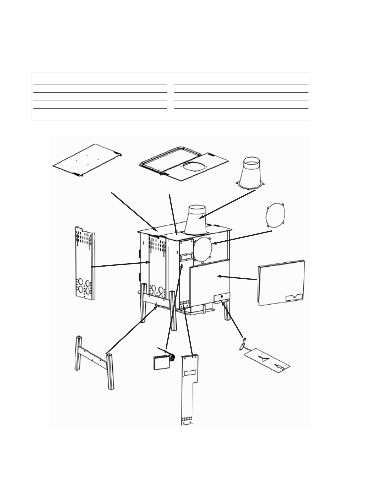
PG-14
Leg “H” Weldment (2)
PG-119 C-Channel
Leg Support (2)
PG-17
Top Lid Assembly
PG-21
Upper Top Assembly
PG-940
Flue Collar
PG-134
Cover Plate
PG-310
Secondary Rear Cover
PG-210
Air Control Plate, shown
with PG 109 Lever
PG-311
Tertiary Rear Cover
PG-23
Tertiary Inlet
Assembly
PG-21 Upper Top Assembly
PG-17 Top Lid Assembly
PG-119 C-Channel Leg Support (2)
PG-14 Leg “H” Weldment (2)
PG-23 Tertiary Inlet Assembly
PG-311 Tertiary Rear Cover
PG-210 Air Control PLate/Linkage
PG-310 Secondary Rear Cover
PG-134 Cover Plate
PG-940 Flue Collar
MODEL 210 ASSEMBLIES, PAGE 2
MODEL 210: IDEAL STEEL HYBRID
30
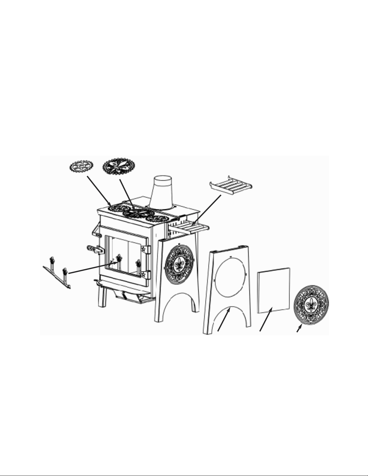
DECORATIVE ACCESSORIES/ATTACHMENTS
PG-18
Andiron Assembly
PG-29
Side Shelf
PG-802 Center
Burner
PG-803 Outside
Burner
PG-305
Fender
UB-204A
Soapstone
Insert
UB-801
Medallion
MODEL 210: IDEAL STEEL HYBRID
31
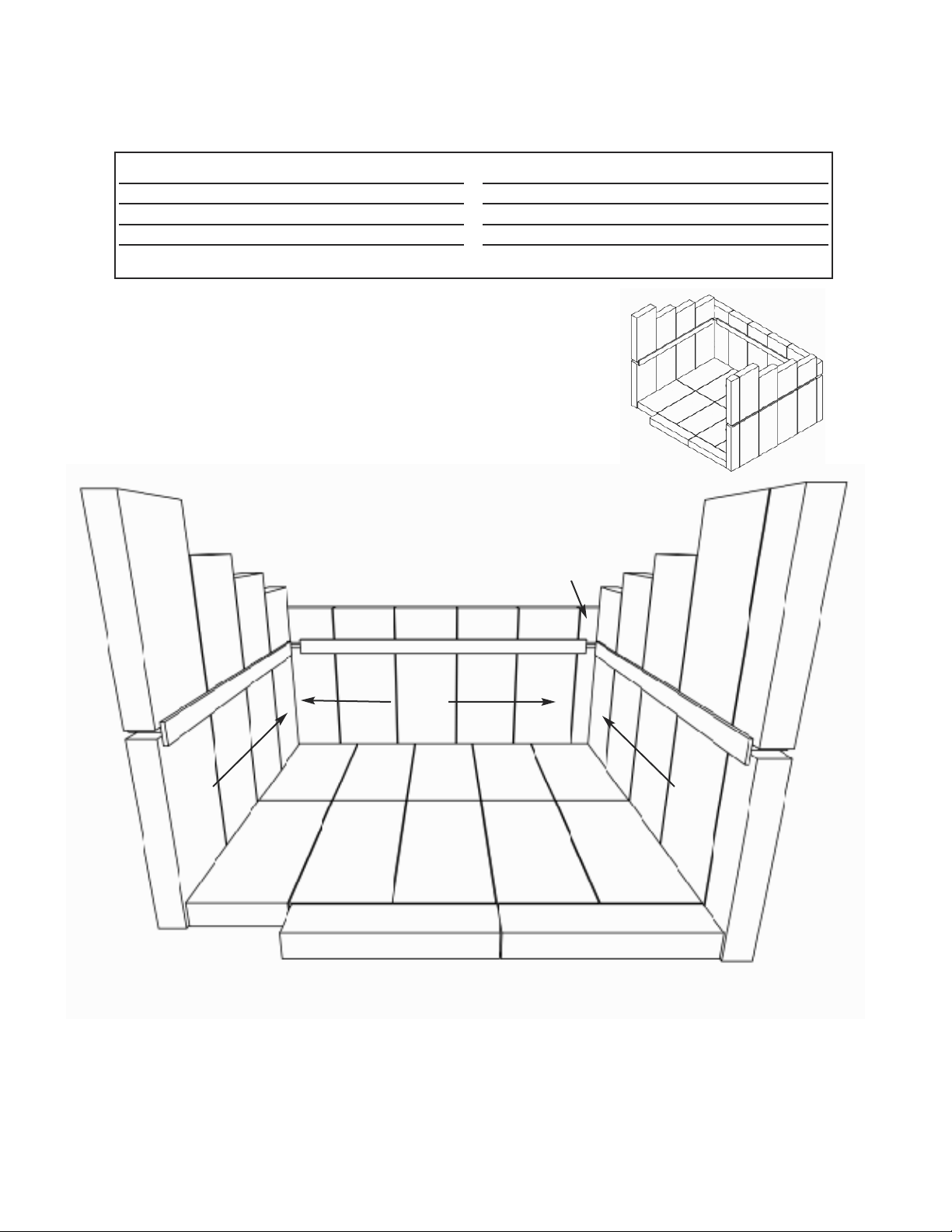
PG-26-A. Soapstone Brick 4.5”x9” (15)
PG-26-B. Soapstone Brick 4.5”x6.5” (2)
PG-26-C. Soapstone Brick 4.5”x 5.25” (2)
PG-26-D. Soapstone Brick 4.5”x 4” (2)
PG-26-E. Soapstone Brick 4.5”x 2.5” (5)
PG-27-F. Soapstone Brick 2.5”x 2.5” (1)
PG-27-G. Soapstone Brick 1.75”x 9” (4)
W-2000. Firebrick 4.5”x9” (10)
PG-26 SOAPSTONE LINER and W-2000 FIREBRICK BASE
MODEL 210: IDEAL STEEL HYBRID
32
2000
2000 2000
200020002000
2000 2000 2000 2000
A
A
A
A
B
B
A
CC
D D
E EEEE
F
G
G
G
G
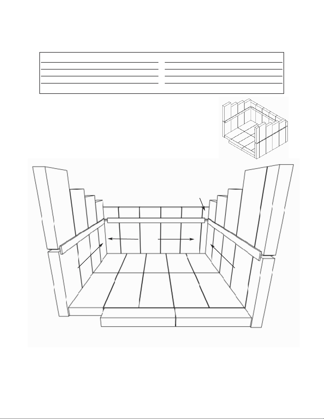
W-2000 FIREBRICK LINER and FIREBRICK BASE
W-2000 Firebrick Back 4.5”x 9” (25)
W-2000-A Firebrick 4.5”x 6.5” (2)
W-2000-B Firebrick 4.5”x 5.25” (2)
W-2000-C Firebrick 4.5”x 4” (2)
W-2000-D Firebrick 4.5”x 2.5” (5)
W-2000-E Firebrick 2.5”x 2.5” (1)
W-2000-F Firebrick 1.75”x 9” (4)
MODEL 210: IDEAL STEEL HYBRID
33
2000
2000 2000
200020002000
2000 2000 2000 2000
2000
2000
2000
2000
A
A
2000
BB
C C
D DDDD
E
F
F
F
F
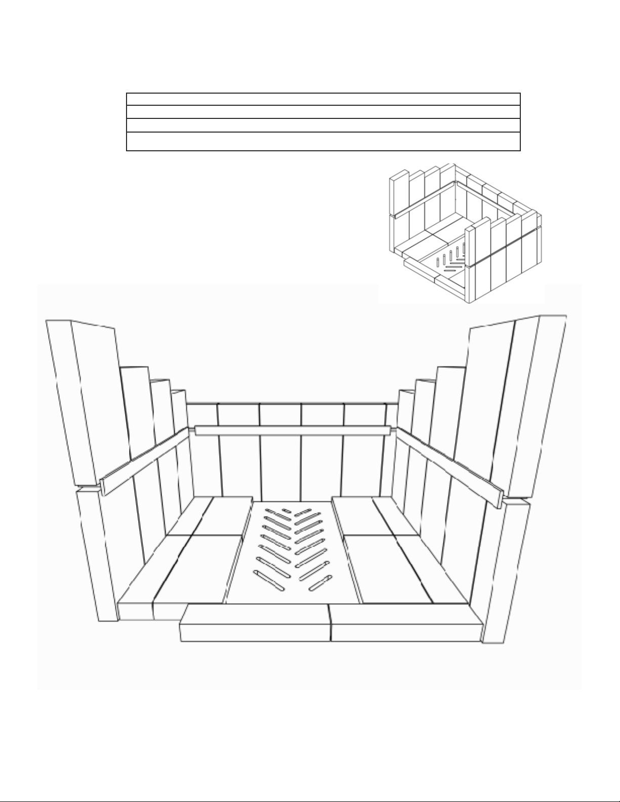
ASH PAN GRATE and W-2000 FIREBRICK BASE
MODEL 210: IDEAL STEEL HYBRID
2000
2000
2000
2000
G
G
G
G
F
F
PG-981 Ash Grate
W-2000 Firebrick Back 4.5”x 9” (4)
W-2000-F Firebrick 1.75”x 9” (2)
W-2000-G Firebrick 2.125”x 9” (4)
34

COMPLETE ASSEMBLIES
PG-14 LEG "H" WELDMENT
PG-305 FENDER
PG-17 TOP LID ASSEMBLY
PG-11 DOOR ASSEMBLY
PG-121 ASH LIP ASSEMBLY
PG-19 SLED ASSEMBLY
PG-22 BYPASS ROD ASSEMBLY
PG-18 ANDIRON
THE FOLLOWING PARTS ARE
FIREBOX
PG-944-140109 STEEL: TERTIARY SEAL PLATE 1
PG-945-140113 HARDWARE: BIMETALLIC COIL 1
PG-136-140113 STEEL: BIMETALLIC PLATE & STUD 1
PG-109 STEEL: AIR CONTROL HANDLE 1
PG-904 STEEL: AIR CONTROL LINK 1
PG-311-131009 STEEL: REAR TERTIARY COVER 1
PG-918 STEEL: RADIATOR 1
PG-134-131106 STEEL: FLUE COVER PLATE 1
PG-940-131104 STEEL: FLUE COLLAR 8 to 6 1
PG-17 TOP LID ASSEMBLY
PG-317-131106 STEEL: SPACER, HEAT SHLD 1
PG-923-131003 STAINLESS: HEAT SHIELD, UPR 1
PG-318-131202 STEEL: PENTAGON SPACER 2
PG-11 DOOR ASSEMBLY
PG-206 STEEL: DOOR FRAME 1
PG-117-130925 STEEL: DOOR HANDLE 1
PG-303.1-131023 STEEL: DOOR GLASS RETAINER 1
PG-118-131107 STEEL: DOOR LATCH 1
PG-933-140113
GLASS: HIGH TEMP 2
PG-16 UPPER BAFFLE ASSEMBLY
PG-217-131001 STEEL: GASKET RETAINER BOW 1
PG-218-131001 STEEL: STR GASKET RETAINER 1
PG-22 BYPASS ROD ASSEMBLY
PG-112-130924 STEEL: BYPASS HANDLE 1
ACCESSORIES
UB-204AA SIDE SOAPSTONE 2
PG-802-140113 CENTER BURNER 1
PG-801-140113 SIDE MEDALLION 2
PG-803-140113
OUTER BURNER
2
PG-16 ASH PAN ASSEMBLY
UB-217, 080513
STEEL: HINGE PIN, ASH DOOR
1
PG-937-131030 STEEL: OUTER ASH DOOR 1
PG-924-131004 STEEL: SPCR, ASHPAN HANDLE 1
PG-124-130924 STEEL: ASH PAN HANDLE 1
PG-130-131029 STEEL: ASH PAN CATCH 1
PG-934-131106
STEEL: ASH PAN
1
COMPLETE ASSEMBLIES AVAILABLE AS REPLACEMENT PARTS
THE FOLLOWING PARTS ARE AVAILABLE FOR EACH ASSEMBLY
PARTS LIST
35

PART SPECIFICATION
Gasket For Top Lid 1.00” Rope
Gasket For Sled Assembly/Bypass Tadpole Gasket
Gasket for Catalyst to Sled 0.625 Wide Flat
Gasket for Load Door 0.750 Rope
Gasket for Ash Pan Door 0.500” Rope
Gasket for Top Lid Assembly 0.250” Rope
Gasket for Glass in Door 0.625” Graphite Tape
Gasket for Flue Collar/Block-off 0.75 Flat Adhesive Gasket (cut in half)
PG-K-535 Catalyst 5.25” x 10” x 2.625” Canned Dim.
Durafoil or equivalent; 49 cells per square inch
GASKET AND CATALYTIC COMBUSTOR SPECIFICATIONS
36
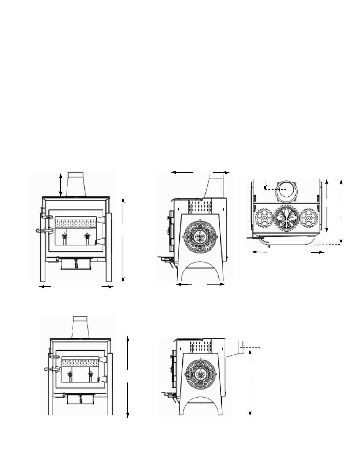
DIMENSIONS & SPECIFICATIONS
H x W x D (Max. Leg Height).....35.5”x29.5”x27.5”
HxWxD (Min Leg Height)........30.5”x29.5”x27.5”
* Cannot have Ash Pan at the Lowest Leg Height
Leg Height Adjustment............5” (in 1” increments)
2020 EPA Certified (cordwood).................Yes
Catalytic Combustor & Secondary Air ....Standard
Listed to UL 1482..............................Yes
Flue Exit..............................Top or Back
Flue Size........................................6”
Flue Height to Center (Max Leg Height).......29.5”
Flue Height to Center (Min. Leg Height).......24.5”
Weight....................................620 lbs.
Ash Pan..................................Optional
* Cannot have Ash Pan at the Lowest Leg Height
EPA Emissions Rating..............0.89 grams/hr
EPA Efficiency.........................82.79% LHV
EPA Efficiency.........................76.94% HHV
Area Heated.....................up to 2,200 sq. ft.
Burn Time................................10-14 hrs.
Heat Output Range.........9,324 - 33,263 BTU/hr
Loading Door................................Front
Loading Door Opening (HxW).............12”x17”
Back Clearance (no protection).................14”
Side Clearance.................................19”
Back Clearance (w/Heat Shield Kit) ............6”
Bottom Heat Shield.......................Standard
Draft Control..............................Manual
Wood Length (Maximum)......................22”
Firebox Size (22”W x 18”D x 12-15” H).....3.2 Cubic/ft.
Window Size (viewable).........................12”H x 17”W
35.5”
Max. Leg Height
23.5”
4.5”
23.5”
27.5”
28” stovetop
20”
Centerline to rear 6” flue
29.5” w/ Max Leg Height
24.5” w/ Min. Leg Height
29.5” leg-to-leg
Min. Leg Height
* Cannot have an Ash Pan at the
Lowest Leg Height
30.5”
Centerline 6”rear flue exit
Back of stove to centerline of
top vent flue approx. 4.5”

GEAR HEAD STOVES
BY WOODSTOCK SOAPSTONE COMPANY