Loading ...
Loading ...
Loading ...
Power supplycord Direct wire
Fire Hazard
This dryer is manufactured with the cabinet-ground
conductor connected to the NEUTRAL (center) of
the wiring harness at the terminal block, if local
codes do NOT permit this type of connection, use
"Four-wire connection" instructions•
GROUNDING INSTRUCTIONS_ This appliance must be
grounded, In the event of malfunction or breakdown,
grounding will reduce the risk of electric shock by
providing a path of least r_sistance for electric current.
If using a power supply cord, the plug must be plugged
into an appropriate outlet that is properly installed and
grounded in accordance with all local codes and
ordinances.
WARNING - Improper connection of the equipment
grounding conductor can result in a risk of electric
shock. Check with a quakged electrician or serviceman
if you are in doubt as to whether the appliance is
propedy grounded, Do not modify the plug provided
with the appliance if it will not fit the outlet, have a
proper outlet installed by a qualified electrician.
If using a direct wire connection, this appliance must be
connected to a grounded metal, permanent wiring
system; or an equipment-grounding conductor must be
run with the circuit conductors and connected to the
equipment grounding terminal or lead on the appliance.
If the house has aluminum wiring, follow the procedure
below: a) Connect a section of 8 gauge solid copper
wire to the connector block, b) Connect the aluminum
wiring to the added section of copper wire using special
connectors designed and Underwriters Laboratories
Listed for joining copper to aluminum Follow the
electrical connector manufacturer's recommended
procedure, C) Aluminum/copper connection must
conform with local codes and industry-accepted wiring
practices.
Use a new UL approved 30 ampere
power supply cord.
Use a UL approved strain relief.
Disconnect power before making
electrical connections.
Connect neutral wire (white or center
wire) to center terminal (silver).
Ground wire (green or bare wire) must
be connected to green ground
connector.
Connect remaining 2 supply wires to
remaining 2 terminals (gold).
Securely tighten all electrical
connections.
Failure to do so can result in death,
fire, or electrical shock.
1, Disconnect the power supply.
external ground
2, Remove hold-down _ / oni'ut_j_or
screw
tab hold
cover.SCrewand terminal block _ dc°reWwn
Fire Hazard
Use fO gauge solid copper wire.
Use a UL approved strain relief.
Disconnect power before making
electrical connections.
Connect neutral wire (white or center
wire) to center terminal (silver).
Ground wire (green or bare wire) must
be connected to green ground
connector.
Connect remaining 2 supply wires to
remaining 2 terminals (gold).
Securely tighten all electrical
connections.
Failure to do so can result in death,
fire, or electrical shock.
sembl 4" strain I d er
3. AS. e 3/ relief _x "'. ¢ar_Inet
U.L.-I sted stra n. clamp ...._
rehef (U.L. marklng sect,ons _ ,,
on strain relief') _/
into the hole below ,_'C> strain relief
terminal block opening, screws
Tighten strain rerief screws just enough to hold
the two clamp sections together. Install power
supply cord/cable through the strain relieh
Complete installation following instructions
for your type of connection:
• Four-wire (recommended method)
• Three-wire (if four-wire isriot available)
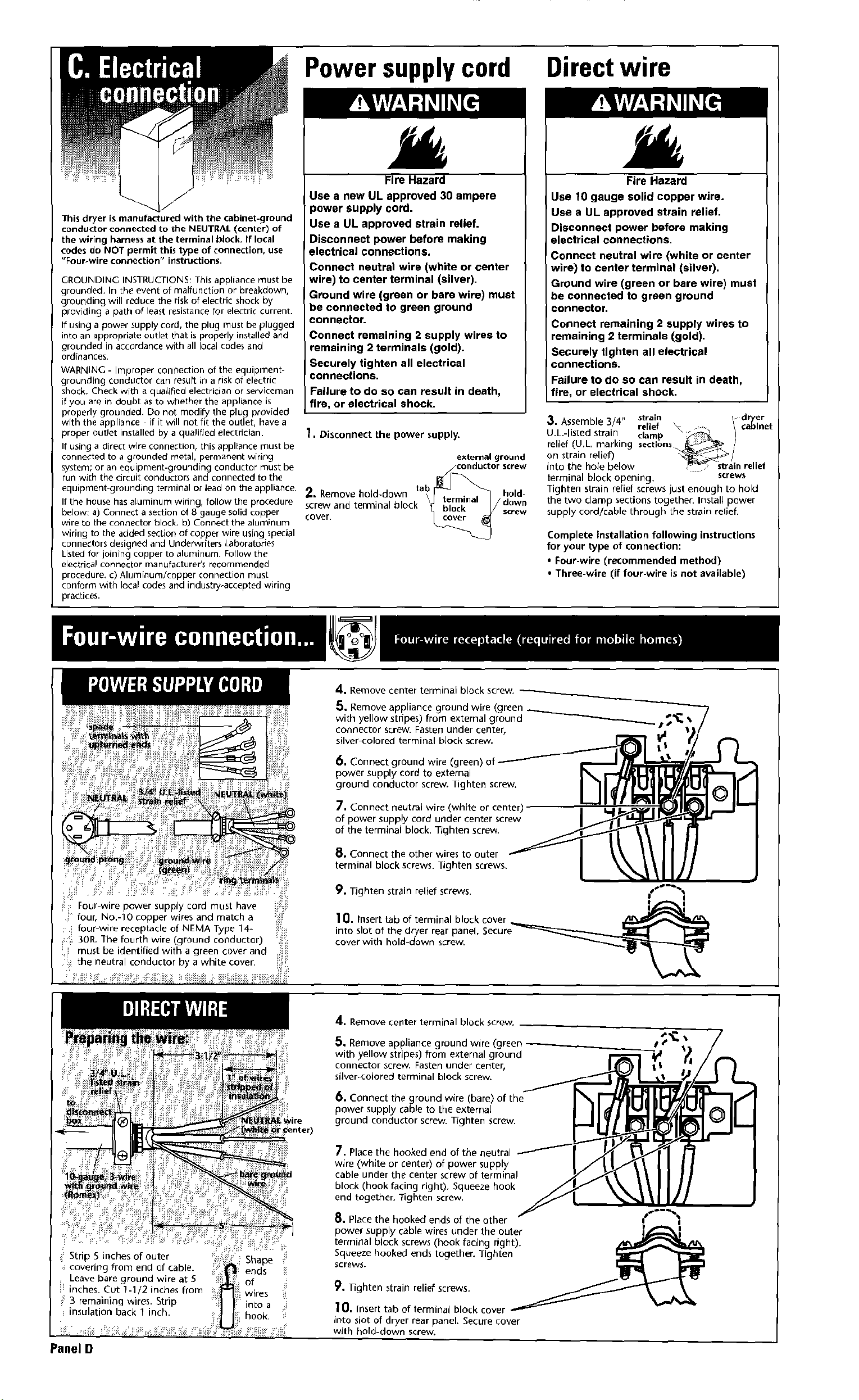
Four wire power supply cord must have
four, No.-lO copper wires and match a
: i four-wire receptacle of NEMA Type 14-
_ 3OR.The fourth wire (ground conductor)
!_ii must be identified with a green cover and i_ii
!_ the neutra conductor by a while cover.
A. Remove center terminal block screw,
5. Remove appliance ground wire (green
with yelJow stripes) from external ground _/_'__
connector screw. Fasten under center,
silver colored terminal bJock screw.
6, Connect ground wire (green)
power supply cord to external
ground conductor screw. Tighten screw.
7, Connect neutral wire (white or center)
of power supply cord under center screw
of the terminal block. Tighten screw.
8, Connect the other wires to outer
terminal block screws. Tighten screws.
9, Tighten strain relief screws. {s_"%
I i
10. Insert tab of terminal block cover
into slot of the dryer rear panel, Secure_
cover with hold-down screw.
Panel D
Shape
_ends ii
of _i
wires
into a
hook.
4. Remove center terminal block screw.
Remove appliance ground wire (green __"
5.
with yellow stripes) from external ground
connector screw. Fasten under center,
silver-colored terminal block screw.
6. Connect the ground wire (bare) of the
power supply cable to the externaJ
ground conductor screw. Tighten screw.
7. Place the hooked end of the ne_
wire (white or center) of power supply
cable under the center screw of terminal
block (hook facing right). Squeeze hook
end together, lighten screw.
_. Place the hooked ends of the other
power supply cable wires under the outer
terminal block screws (hook facing right).
Squeeze hooked ends together. Tighten
screws.
9. Nghten strain relief screws.
lO, Insert tab of terminal block cover
into slot of dryer rear panel. Secure cover
with hold-down screw.
Loading ...
Loading ...
Loading ...