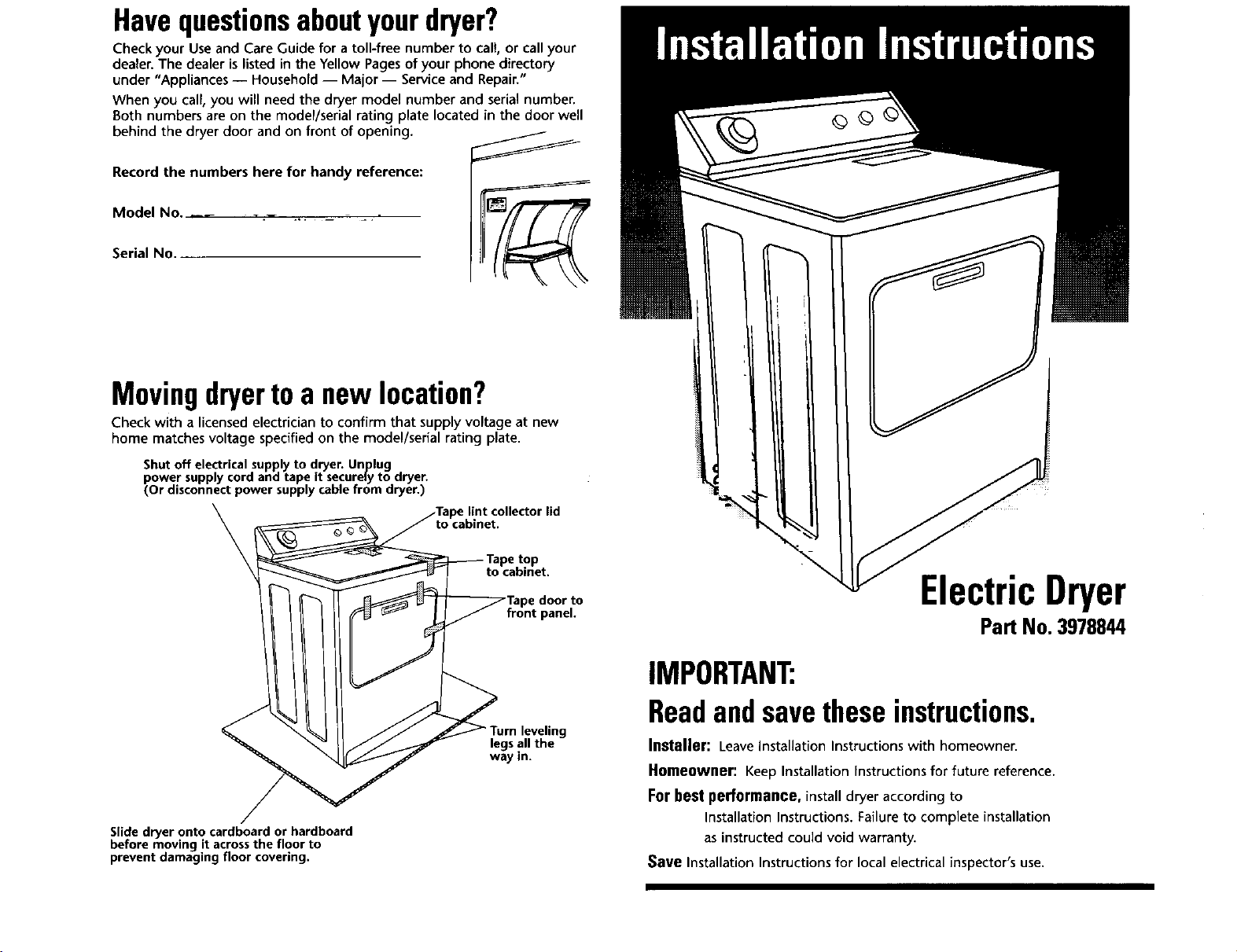
Havequestionsaboutyourdryer?
Check your Use and Care Guide for a toll-free number to call, or call your
dealer. The dealer is listed in the Yellow Pages of your phone directory
under "Appliances -- Household -- Major -- Service and Repair."
When you call, you will need the dryer model number and serial number.
Both numbers are on the model/serial rating plate located in the door well
behind the dryer door and on front of opening.
Record the numbers here for handy reference:
Model No, _ __ _J,/_'/'/_
Serial No
Movingdryertoa newIocatzon?
Check with a licensed electrician to confirm that supply voltage at new
home matches voltage specified on the model/serial rating plate.
Shutoff electrical supplyto dryer. Unplug
power supplycord and tape it securelyto dryer.
(Or disconnectpower supplycablefrom dryer.)
\
door to
panel.
ElectricDryer
Pa_ No. 3978844
Slide dryer onto cardboard or hardboard
before moving it across the floor to
prevent damaging floor covering.
leveling
legs all the
way in.
IMPORTANT:
Readandsavetheseinstructions.
Installer: Leave installation Instructions with homeowner.
Homeowner: Keep Installation instructions for future reference.
For best performance, install dryer according to
Installation Instructions. Failure to complete installation
as instructed could void warranty.
Save Installation Instructions for local electrical inspector's use.
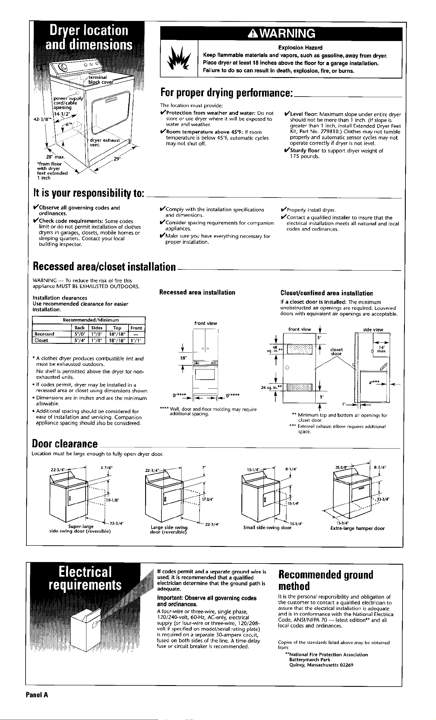
Explosion Hazard
Keep flammable materials and vapors, such as gasoline, away from dryer.
Place dryer at least 18 inches above the floor for a garage installation.
Failure to do so can result in death, explosion, fire, or burns.
Forproperdryingperformance:
The location must provide:
b/Protection from weather and water: Do not
store or use dryer where it will be exposed to
water and weather.
I/Room temperature above 4S°F: If room
temperature is below 45°F, automatic cycles
may not shut off.
I/Level floor: Maximum slope under entire dryer
should not be more than 1 inch. (If slope is
greater than I inch, install Extended Dryer Feet
Kit, Part No. 279810.) Clothes may not tumble
properly and automatic sensor cycles may not
operate correctly if dryer is not level.
I/Sturdy floor to support dryer weight of
175 pounds.
1 inch
It isyourresponsibilityto:
I/Observe all governing codes and
ordinances.
I/Check code requirements: Some codes
limit or do not permit installation of clothes
dryers in garages, closets, mobile homes or
sleeping quarters. Contact your local
building inspector.
I/Comply with the installation specifications
and dimensions.
I/Consider spacing requirements for companion
appliances.
I/Make sure you have everything necessary for
proper installation.
I/Properly install dryer.
I/Contact a qualified installer to insure that the
electrical installation meets all national and local
codes and ordinances,
Recessedarea/closetinstallation
WARNING To reduce the risk of fire this
appliance MUST BE EXHAUSTED OUTDOORS•
Installation clearances
Use recommended clearance for easier
installation.
Recommended/Minim um
Back Sides Top Front
Recessed 5"/0" 1"/0" 18"/18" --
Closet 5"/4" 1"/0" 18"/18" 1"/1"
* A clothes dryer produces combustible lint and
must be exhausted outdoors.
No shelf is permitted above the dryer for non-
exhausted units.
• If codes permit, dryer may be installed in a
recessed area or closet using dimensions shown•
• Dimensions are in inches and are the minimum
allowable.
• Additional spacing should be considered for
ease of installation and servicing, Companion
appliance spacing should also be considered.
Doorclearance
Location must be large enough to fully open dryer door.
Recessed area installation
front view
I
**** Wall, door and floor molding may require
additional spacing.
Closet!confined area installation
If a closetdoor isinstalled:The minimum
unobstructed air openings are required. Louvered
doors with equivalent air openings are acceptable.
** Minimum top and bottom air openings for
closet door
***Externalexhaustelbowrequiresadditiona!
space.
15-i/4', _ 8 I/4"
J
11 14'
J * ,
J _ 15.1/4, '
Small side-swing door
13-3/4"
£xtra-large hamper door
If codes permit and a separate ground wire is
used, it is recommended that a qualified
electrician determine that the ground path is
adequate,
Important: Observe all governing codes
and ordinances.
A four-wire or three-wire, single phase,
120/240-volt, 60-Hz, At-only, e_ectrical
supply (or four-wire or three-wire, 120/208-
volt if specified on model/serial rating plate)
is required on a separate 30-ampere circuit,
fused on both sides of the line. A time delay
fuse or circuit breaker is recommended.
Recommendedground
method
It is the personal responsibility and obligation of
the customer to contact a qualified electrician to
assure that the electrical installation is adequate
and is in conformance with the National Electrical
Code, ANSI/NFPA 70 -- latest edition** and all
local codes and ordinances•
Copies of the standards listed above may be obtained
from:
**National Fire Protection Association
Batterymarch Park
Quincy, Massachusetts 02269
Panel A
Fire Hazard
Usea heavy metal vent.
Do not use a plastic vent.
Do not usea metalfoil vent.
Failureto follow there instructionscan
result in death or fire,
• DO Not use non-metal flexible vent or
exhaust hoods with magnetic latches.
• Metal exhaust vent must be four inches in
diameter•
• Do Not exhaust dryer into a chimney,
furnace, cold air vent, attic or crawl space,
or any other vent used for venting.
• DO Not install flexible vent in enclosed
walls, ceilings or floors•
Important: Observe all governing codes and
ordinances.
A dryer must be exhausted outdoors.
Moisture and rint indoors may cause:
• Lint to gather around the dryer where it can
de fuel for a fire.
• Moisture damage to woodwork, furniture,
paint, wallpaper, carpet, etc.
• Housecleaning problems and health problems.
Dura SafeTM venting products are
recommended and are available from your
dealer.
Four-inch diameter vent is required.
Rigid or flexible metal exhaust vent must be
used. Do Not use plastic or metal foil vent.
Rigid metal vent is recommended to prevent
crushing and kinking.
Flexible metal vent must be fully extended and
supported when the dryer is in its final position.
Remove excess flexible vent to avoid sagging
and kinking that may result in reduced airflow.
An exhaust hood should cap the exhaust vent
to prevent rodents and
insectsfrom entering the
home.
Exhaust outlet hood must -- "_.
be at least 12 inches from --
the ground or any obiect --_
that may be in the path of --
the exhaust (such as flowers,
rocks or bushes, etc.)
If using an existing
exhaust system, clean lint from entire length
of system and make sure exhaust hood is not
plugged with lint, Replace any plastic or metal
foil vent with rigid metal or flexible metal vent.
Use clamps to seal all joints. Do Not use duct
tape, screws or other fastening devices that
extend into the interior of the vent to secure
vent.
Service check: Back pressure in any exhaust
system used must not exceed 0.6 inches in
water column measured with an incline
manometer at the point that exhaust vent
connects to dryer.
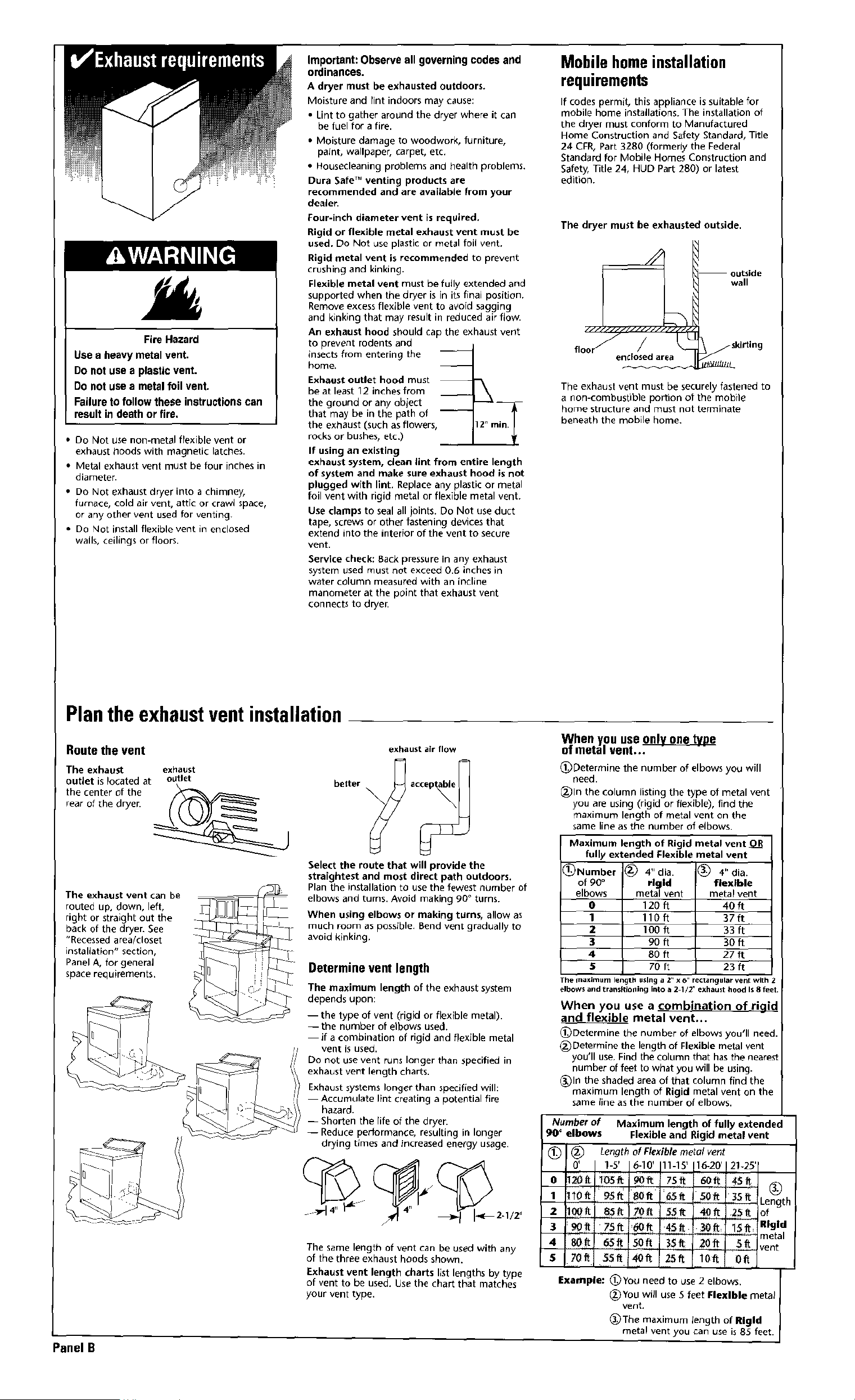
Mobile homeinstallation
requirements
If codes permit, this appliance is suitable for
mobile home installations. The installation of
the dryer must conform to Manufactured
Home Construction and Safety Standard, Title
24 CFR, Part 3280 (formerly the Federal
Standard for Mobile Homes Construction and
Safety, title 24, HUD Part 280) or latest
edition.
The dryer must be exhausted outside.
wall
floor
elldosed area
The exhaust vent must be securely fastened to
a non-eombus0ble portion of the mobile
home structure and must not terminate
beneath the mobile home.
Plantheexhaustventinstallation
Route the vent
The exhaust exhaust
outlet is located at outlet
the center of the _. _
rear of the dryer.
The exhaust vent can be
routed up, down, left,
right or straight out the
back of the dryer. See
"Recessed area/closet
installation" section,
Panel A, for general
space requirements.
exhaust air flow
better ac_
Select the route that will provide the
straightest and most direct path outdoors.
Plan the installation to use the fewest number of
elbows and turns. Avoid making 90 o turns.
When using elbows or making turns, allow as
much room as possible. Bend vent gradually to
avoid kinking.
Determine ventlength
The maximum length of the exhaust system
depends upon:
-- the type of vent (rigid or flexible metal)•
-- the number of elbows used.
if a combination of rigid and flexible metal
vent is used,
Do not use vent runs longer than specified in
exhaust vent length charts.
Exhaust systems longer than specified will:
Accumulate lint creating a potential fire
hazard•
-- Shorten the lifeof the dryer•
-- Reduce performance, resulting in longer
drying times and increased energy usage.
_4 _ _/_2.tJZ r,
The same length of vent can be used with any
of the three exhaust hoods shown.
Exhaust vent length charts list lengths by type
of vent to be used. Use the chart that matches
your vent type.
When you use
of metal vent...
(_)Determine the number of elbows you will
need.
_)ln the column listing the type of metal vent
you areusing (rigid or flexible), find the
maximum length of metal vent on the
same line asthe number of elbows.
_Number
of 90°
elbows
O
1
2
3
4
$
The_axJmumlem
Maximum length of Rigid metal vent
fully extended Flexible metal vent
4" dia. _ 4" dia.
rigid flexible
metal vent metal vent
120ft 4Oft
11Oft 37ff
100 ft 33 ft
90ft 3Oft
80 ft 27 ft
70 ft 23 ft
Lh ushlg a 2" x 6" rectangular vent with Z
elbows and trallSlllolling into a 2 1/2" exhaust hood Is 8 feel.
When you use a combination of tiaid
and flexible metal vent...
_)Determine the number of elbows you'll need.
(_Determine the length of Flexible metal vent
you'll use. Find the column that has the nearest
number of feet to what you will be using.
_)ln the shaded area of that column find the
maximum length of Rigid metal vent on the
same line as the number of elbows.
Number of Maximum length of fully extended
90" elbows Flexible and Rigid metal vent
_ Length of Flexible metal vent
O' 1-8' 16-I0' 111-15' 116-20'121-25'r
0 20 t 1os 9oft 7s t 6oft
1 10ft" 95ft _Oft ]:d,,S_ ,,,SOft 35ff Length
2 OOft 85_ Yo_ _ft "I0ft 2_ of
3 90ff 75ft :,_ 45ft _ft lSft: Rigid
" ................... _ metal
4 80it 6_f_ 50ff 3$ft 20ft _& vent
s 70f_ $5n 4off 25ff IOf_ 0ft
Example: _)You need to use 2 elbows.
(_You will use 5 feet Flexlble metal
vent.
_)The maximum length of Rlgld
metal vent you can use is 85 feet.
Panel B
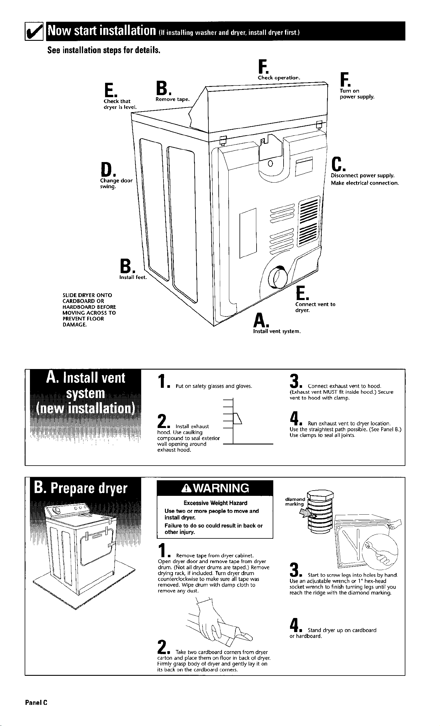
See installationstepsfordetails.
E, B,
Check that Remove tape,
dryer is level.
E
Check operation.
F.
Turn on
power supply.
DI
Change door
swing.
Cn
Disconnect power supply.
Make electrical connection.
SLIDE DRYER ONTO
CARDBOARD OR
HARDBOARD BEFORE
MOVING ACROSS TO
PREVENT FLOOR
DAMAGE.
Install feet.
EN
Connect vent to
dryer.
A.
Install vent system.
l m Put on safety glasses and gloves•
• Install exhaust _ "_
hood. Use caulking
compound to seal exterior
wall opening around
exhaust hood.
m Connect exhaust vent to hood•
(Exhaust vent MUST fit inside hood•) Secure
vent to hood with clamp•
m Run exhaust vent to dryer location.
Use the straightest path possible. (See Panel B.)
Use clamps to seal all joints.
Excessive Weight Hazard
Use two or more people to move and
install dryer,
Failure to do so could result in back or
other injury.
• Remove tape from dryer cabinet.
Open dryer door and remove tape from dryer
drum. (Not all dryer drums are taped.) Remove
drying rack, if included. Turn dryer drum
counterclockwise to make sure all tape was
removed. Wipe drum with damp cloth to
remove any dust.
diamond
marking
u Start to screw legs into holes by hand.
Use an adjustable wrench or I" hex-head
socket wrench to finish turning legs untir you
reach the ridge with the diamond marking.
n Take two cardboard corners from dryer
car[on and place them on floor in back of dryer.
Firmly grasp body of dryer and gently lay it on
its back on the cardboard corners.
1 Stand dryer up on cardboard
or hardboard.
PanelC
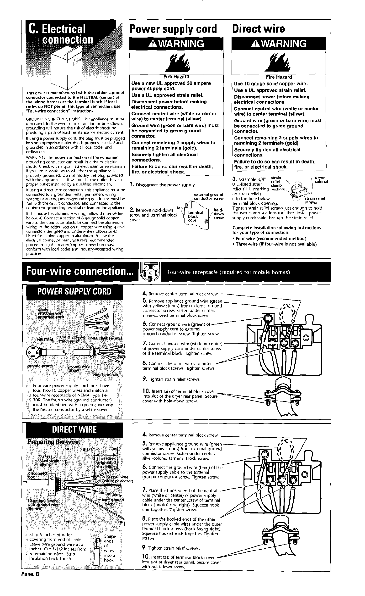
Power supplycord Direct wire
Fire Hazard
This dryer is manufactured with the cabinet-ground
conductor connected to the NEUTRAL (center) of
the wiring harness at the terminal block, if local
codes do NOT permit this type of connection, use
"Four-wire connection" instructions•
GROUNDING INSTRUCTIONS_ This appliance must be
grounded, In the event of malfunction or breakdown,
grounding will reduce the risk of electric shock by
providing a path of least r_sistance for electric current.
If using a power supply cord, the plug must be plugged
into an appropriate outlet that is properly installed and
grounded in accordance with all local codes and
ordinances.
WARNING - Improper connection of the equipment
grounding conductor can result in a risk of electric
shock. Check with a quakged electrician or serviceman
if you are in doubt as to whether the appliance is
propedy grounded, Do not modify the plug provided
with the appliance if it will not fit the outlet, have a
proper outlet installed by a qualified electrician.
If using a direct wire connection, this appliance must be
connected to a grounded metal, permanent wiring
system; or an equipment-grounding conductor must be
run with the circuit conductors and connected to the
equipment grounding terminal or lead on the appliance.
If the house has aluminum wiring, follow the procedure
below: a) Connect a section of 8 gauge solid copper
wire to the connector block, b) Connect the aluminum
wiring to the added section of copper wire using special
connectors designed and Underwriters Laboratories
Listed for joining copper to aluminum Follow the
electrical connector manufacturer's recommended
procedure, C) Aluminum/copper connection must
conform with local codes and industry-accepted wiring
practices.
Use a new UL approved 30 ampere
power supply cord.
Use a UL approved strain relief.
Disconnect power before making
electrical connections.
Connect neutral wire (white or center
wire) to center terminal (silver).
Ground wire (green or bare wire) must
be connected to green ground
connector.
Connect remaining 2 supply wires to
remaining 2 terminals (gold).
Securely tighten all electrical
connections.
Failure to do so can result in death,
fire, or electrical shock.
1, Disconnect the power supply.
external ground
2, Remove hold-down _ / oni'ut_j_or
screw
tab hold
cover.SCrewand terminal block _ dc°reWwn
Fire Hazard
Use fO gauge solid copper wire.
Use a UL approved strain relief.
Disconnect power before making
electrical connections.
Connect neutral wire (white or center
wire) to center terminal (silver).
Ground wire (green or bare wire) must
be connected to green ground
connector.
Connect remaining 2 supply wires to
remaining 2 terminals (gold).
Securely tighten all electrical
connections.
Failure to do so can result in death,
fire, or electrical shock.
sembl 4" strain I d er
3. AS. e 3/ relief _x "'. ¢ar_Inet
U.L.-I sted stra n. clamp ...._
rehef (U.L. marklng sect,ons _ ,,
on strain relief') _/
into the hole below ,_'C> strain relief
terminal block opening, screws
Tighten strain rerief screws just enough to hold
the two clamp sections together. Install power
supply cord/cable through the strain relieh
Complete installation following instructions
for your type of connection:
• Four-wire (recommended method)
• Three-wire (if four-wire isriot available)
Four wire power supply cord must have
four, No.-lO copper wires and match a
: i four-wire receptacle of NEMA Type 14-
_ 3OR.The fourth wire (ground conductor)
!_ii must be identified with a green cover and i_ii
!_ the neutra conductor by a while cover.
A. Remove center terminal block screw,
5. Remove appliance ground wire (green
with yelJow stripes) from external ground _/_'__
connector screw. Fasten under center,
silver colored terminal bJock screw.
6, Connect ground wire (green)
power supply cord to external
ground conductor screw. Tighten screw.
7, Connect neutral wire (white or center)
of power supply cord under center screw
of the terminal block. Tighten screw.
8, Connect the other wires to outer
terminal block screws. Tighten screws.
9, Tighten strain relief screws. {s_"%
I i
10. Insert tab of terminal block cover
into slot of the dryer rear panel, Secure_
cover with hold-down screw.
Panel D
Shape
_ends ii
of _i
wires
into a
hook.
4. Remove center terminal block screw.
Remove appliance ground wire (green __"
5.
with yellow stripes) from external ground
connector screw. Fasten under center,
silver-colored terminal block screw.
6. Connect the ground wire (bare) of the
power supply cable to the externaJ
ground conductor screw. Tighten screw.
7. Place the hooked end of the ne_
wire (white or center) of power supply
cable under the center screw of terminal
block (hook facing right). Squeeze hook
end together, lighten screw.
_. Place the hooked ends of the other
power supply cable wires under the outer
terminal block screws (hook facing right).
Squeeze hooked ends together. Tighten
screws.
9. Nghten strain relief screws.
lO, Insert tab of terminal block cover
into slot of dryer rear panel. Secure cover
with hold-down screw.
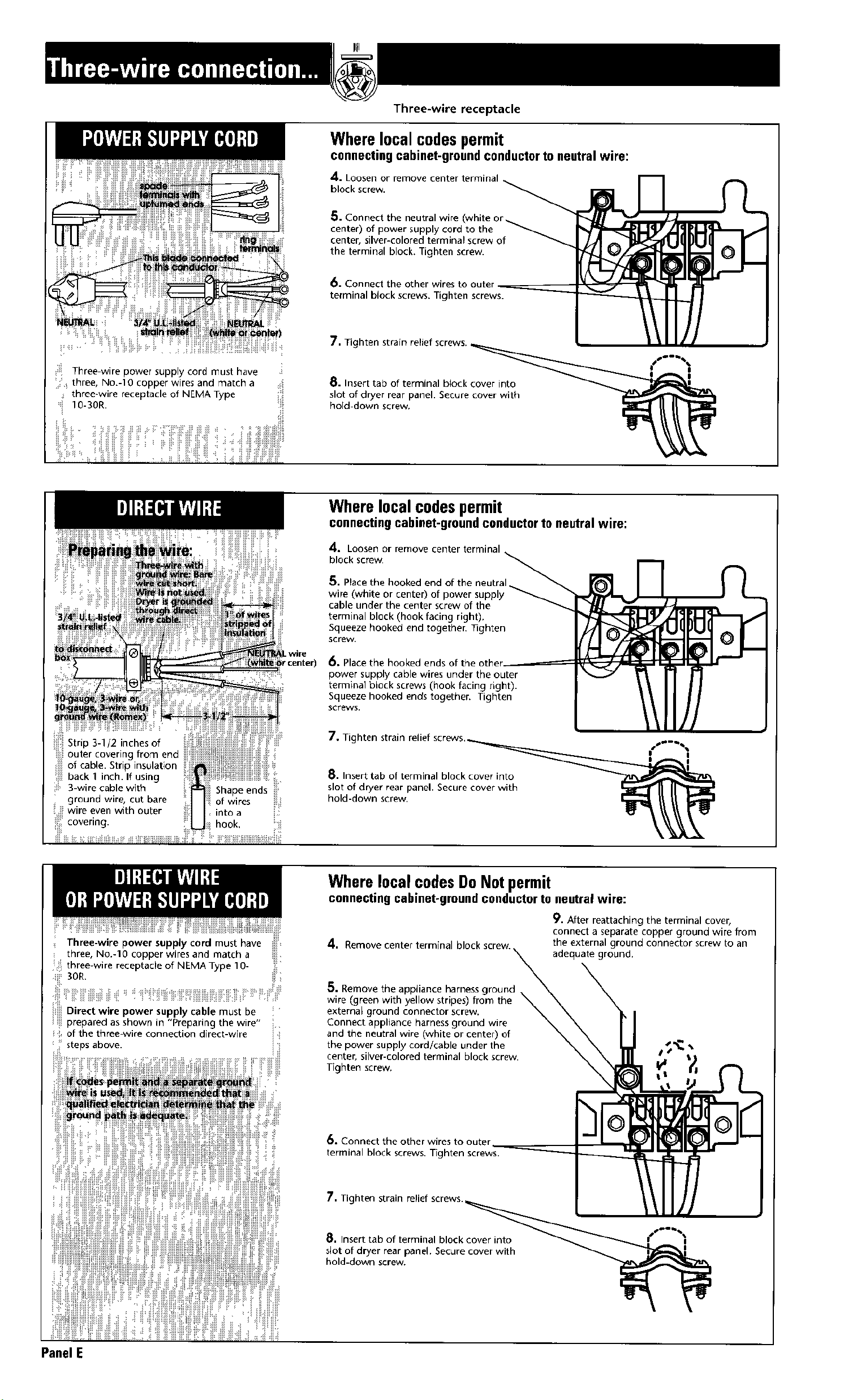
Three wire power supply cord must have
three, No.-10 copper wires and match a
three-wire receptacle of NEMA Type
I0-30R.
Three-wire receptacle
Where local codespermit
connecting cabinet-ground conductor to neutral wire:
4. Loosen or remove
block screw,
_. Connect the neutral wire
center) of power supply cord to the
center, silver-colored terminal screw of
the terminal block. Tighten screw•
6. Connect the other wires to outer _
terminal block screws. Tighten screws.
7, Tighten strain relief screws.
8. Insert tab of terminal block cover into
slot of dryer rear panel. Secure cover with
hold down screw.
OI
wire
reenter)
Where local codespermit
connecting cabinet-ground conductor 1o neutral wire:
4. Loosen or remove center terminal
block screw.
5. Place the hooked end of the neutral
wire (white or center) of power supply
cable under the center screw of the
terminal block (hook facing right).
Squeeze hooked end together. 7]ghten
screw.
6, Place the hooked ends of the other
power supply cable wires under the outer
terminal block screws (hook facing right).
Squeeze hooked ends together. Tighten
screws.
7. Tighten strain relief screws_•
8. Insert tab of terminal block cover into
slot of dryer rear panel. Secure cover with
hold-down screw.
I i
Three-wire power supply cord must have
three, No.-10 copper wires and match a
three-wire receptacle of NEMA Type 10-
SOR.
Direct wire power supply cab e mus be
prepared as shown in "Preparing the wire"
, of the three wire connection direct-wge
steps above.
Where local codesDo Notpermit
connecting cabinet-ground conductor to neutral wire:
9. After reattaching the terminal cover,
connect a separate copper ground wire from
4. Remove center terminal block screw, the external ground connector screw to an
adequate ground.
5, Remove the appliance harness ground
wire (green with yellow stripes) from the
external ground connector screw.
Connect appliance harness ground wire
and the neutral wire (white or center) of
the power supply cord/cable under the
center, silver-colored terminal block screw.
Tighten screw,
6. Connect the other wires to outer
terminal block screws, Tighten screws.
7, Tighten strain relief screws._
8,1nsert tab of terminal block cover into __ .If"'_f""
slot of dryer rear panel. Secure cover with _ _
hold-down screw, cover with
Panel E
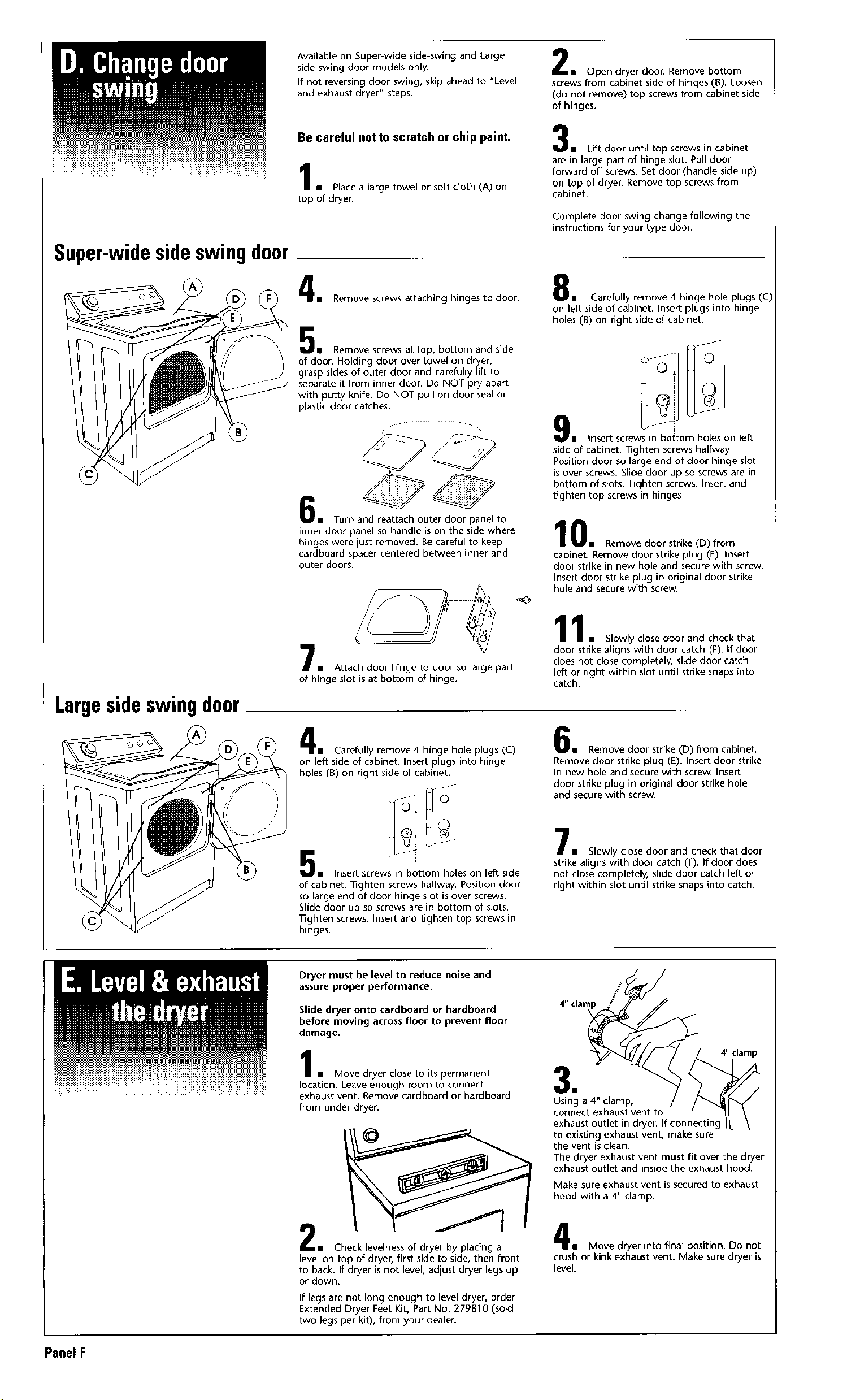
Super-widesideswingdoor
Available on Super-wide side-swing and Large
side-swing door models only•
If not reversing door swing, skip ahead to "Level
and exhaust dryer" steps.
Be careful not to scratch or chip paint.
11 Placea large towel or soft cloth(A) on
top of dryer.
1 Open dryer door. Remove bottom
screws from cabinet side of hinges (B). Loosen
(do not remove} top screws from cabinet side
of hinges.
m Lift door until top screws in cabinet
are in large part of hinge slot. Pull door
forward off screws• Set door (handle side up)
on top of dryer• Remove top screws from
cabinet•
Complete door swing change following the
instructions for your type door.
m Remove screws attaching hinges to door.
m Remove screws at top, bottom and side
of door• Holding door over towel on dryer,
grasp sides of outer door and carefully lift to
separate it from inner door• Do NOT pry apart
with putty knife. Do NOT pull on door seal or
plastic door catches.
u Turn and reattach outer door panel to
inner door panel so handle is on the side where
hinges were just removed. Be careful to keep
cardboard spacer centered between inner and
outer doors.
• Carefully remove 4 hinge hole plugs (C)
on left side of cabinet. Insert plugs into hinge
holes (B) on right side of cabinet•
• Insert screws in bottom holes on left
side of cabinet. Tighten screws halfway.
Position door so large end of door hinge slot
is over screws. Slide door up so screws are in
bottom of slots. Nghten screws. Insert and
tighten top screws in hinges•
0• Remove door strike (D) from
cabinet• Remove door strike plug (E). insert
door strike in new hole and secure with screw•
Insert door strike plug in original door strike
hole and secure with screw.
Largesideswingdoor
m Attach door hinge to door so large part
of hinge slot is at bottom of hinge.
1. Slowly close door and check that
door strike aligns with door catch (It). If door
does not close completely, slide door catch
left or right within slot until strike snaps into
catch.
• Carefully remove 4 hinge hole plugs (C)
on left side of cabinet. Insert plugs into hinge
holes (B) on right side of cabinet.
• Insert screws in bottom holes on left side
of cabinet. Hghten screws halfway. Position door
so large end of door hinge slot is over screws•
Slide door up so screws are in bottom of slots.
Tighten screws• Insert and tighten top screws in
hinges•
w Remove door strike (D) from cabinet.
Remove door strike plug (E). Insert door strike
in new hole and secure with screw. Insert
door strike plug in original door strike hole
and secure with screw.
• Slowly close door and check that door
strike aligns with door catch (F). If door does
not close completely, slide door catch left or
right within slot until strike snaps into catch.
Dryer must be level to reduce noise and
assure proper performance.
Slide dryer onto cardboard or hardboard
before moving across floor to prevent floor
damage.
I • Move dryer close to its permanent
location. Leave enough room to connect
exhaust vent. Remove cardboard or hardboard
from under dryer.
2.
Check levelness of dryer by placing a
level on top of dryer, first side to side, then front
to back. If dryer is not level, adjust dryer legs up
or down,
If legs are not long enough to level dryer, order
Extended Dryer Feet Kit, Part No. 279810 (sold
two legs per kit), from your dealer.
4' clamp
•
Using a 4" clamp,
connect exhaust vent to
exhaust outlet in dryer. If connecting
to existing exhaust vent, make sure
the vent is clean.
The dryer exhaust vent must fit over the dryer
exhaust outlet and inside the exhaust hood.
Make sure exhaust vent is secured to exhaust
hood with a 4" clamp.
• Move dryer into final position. Do not
crush or kink exhaust vent. Make sure dryer is
level.
Panel F
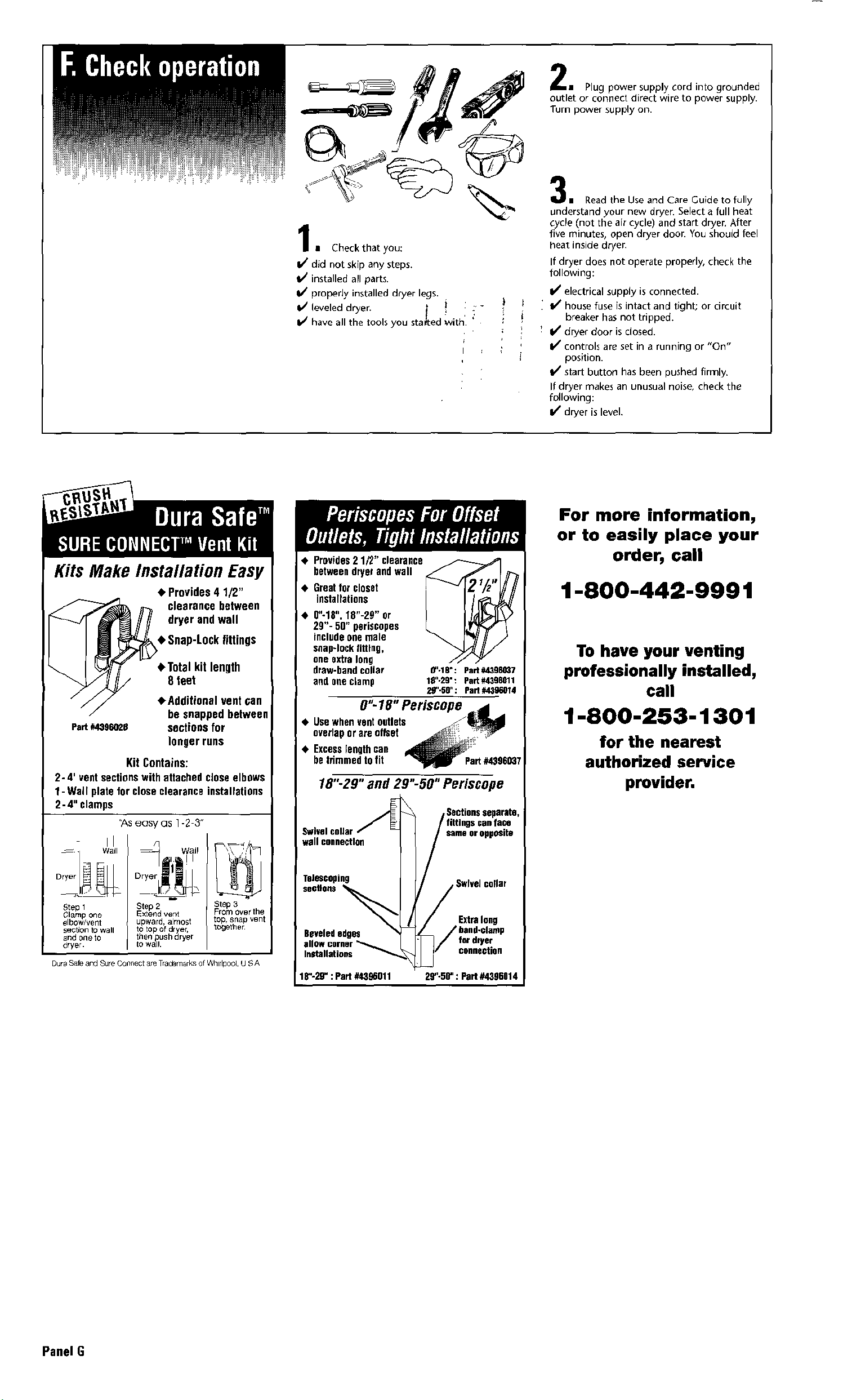
11 Check that you:
If did not skip any steps.
installed all parts.
I/propedy installed dryer legs.
11/leveled dryer. _ i -
lJ have all the tools you started with. '
1 Plug power supply cord into grounded
outlet or connect direct wire to power supply.
Turn power supply on.
m Read the Use and Care Guide to fully
understand your new dryer. Select a full heat
cycle (not the air cycle) and start dryer. After
five minutes, open dryer door. You should feel
heat inside dryer.
If dryer does not operate properly, check the
following:
I,/ electrical supply is connected.
i If house fuse is intact and tight; or circuit
breaker has not tripped.
' kd dryer door is dosed.
If controls are set in a running or "On"
position.
Ill start button has been pushed firmly.
If dryer makes an unusual noise, check the
following:
If dryer is level.
Kits Make Installation Easy
clearance between
dryer and wall
• Total kit length
8 ]eet
eAdditional vent can
be snapped between
Part#4396025 sections for
longer runs
Kit Contains:
2- 4' ventsectionswith attached closeelbows
1- Wall platefor close clearanceinstallations
2- 4" clamps
%s easy as 1-2 3"
Step 1 Step 2 Step 3
Olamp One E×teNd vent From over the
_lbow/veNt upwar(k almost toP, snap vBnt
section to wall to top of dryer, totJether
_nd One to then push dryer
dryer, to wall.
Dura Safe and Sure (/ollnect are Trademarks of WhlrlDool U _ A
• Provides2 1/2" clearance
between dryer and wall
• Greatfor closet
installations
• 0"-18", 19"-29" or
29"- 50" periscopes
include one male
cJlap-lockfitting,
one extra long
draw-bandcollar
and one clamp
e'.18-: Part #439m_7
le'.29.: part #4398011
2_'-50" : Part #439_014
0"-18" Periscope r,4 .
• Usewhen vent outlets
overlapor are offset _
• Excesslength can
be trimmed to fit _Part #43960_7
18".29"and 29"-50" Per_cope
Swivelcolla_
wall connection
scantac@
same or opposite
Telescoping Swivel collar
sections
Beveled edges
InStallat ion_
18"-29" : Part #4396011
Extralong
fordrper
connection
2S"-56":Part#4396014
For more information,
or to easily place your
order, call
1-800-442-9991
To have your venting
professionally installed,
call
1-800-253-1301
for the nearest
authorized service
provider.
Panel G
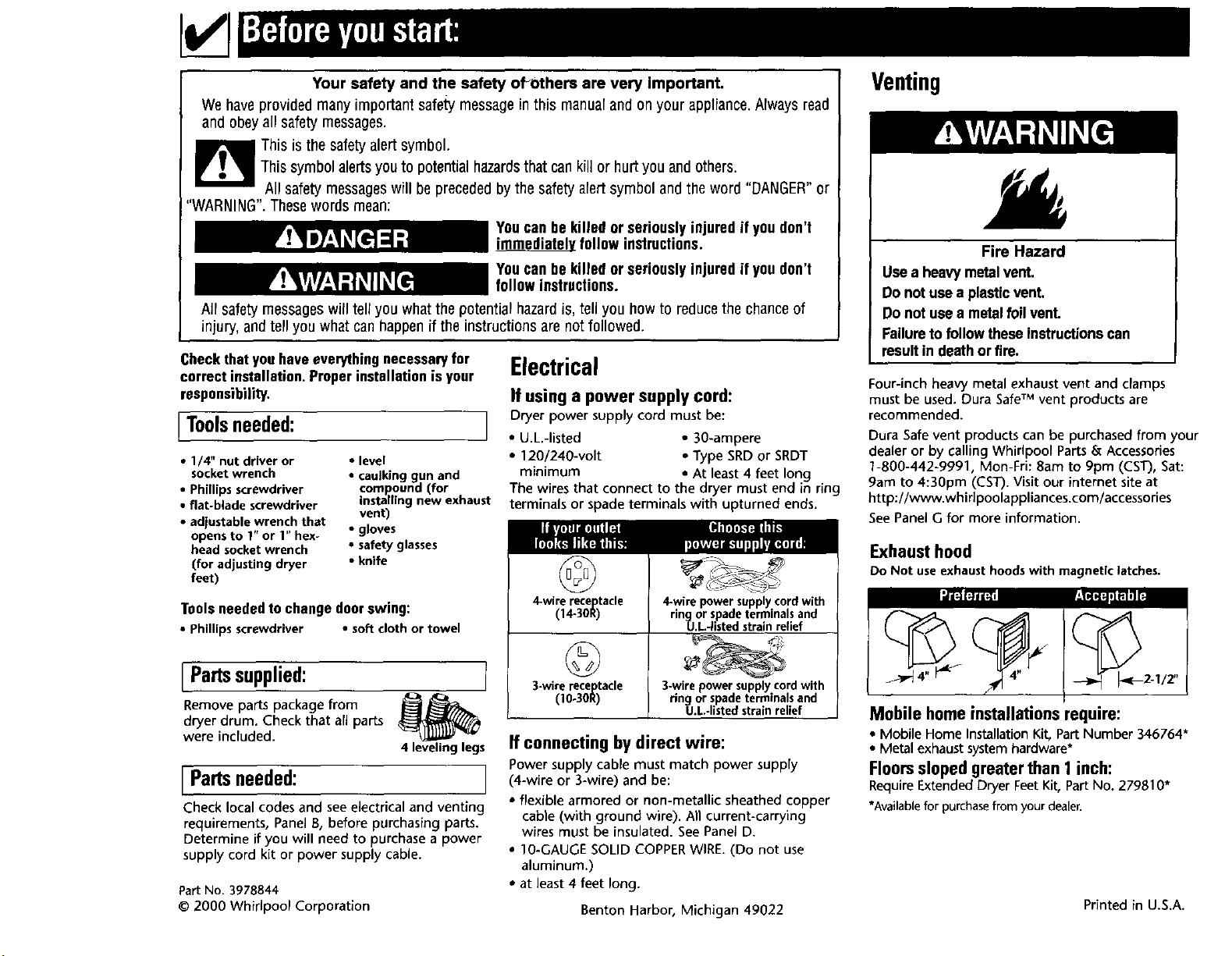
Your safety and the safety of_others are very Important.
We haveprovided many important safetymessagein this manualand onyour appliance.Nways read
and obeyall safety messages.
This is the safety alert symbol.
This symbol alertsyou to potential hazardsthat cankill or hurt you and others.
All safety messageswill be precededbythe safetyalertsymbol andthe word "DANGER"or
"WARNING".Thesewords mean:
Youcan bekilled or seriouslyinjured if youdon't
i_ follow instructions.
Youcan bekilled or seriouslyinjured if youdon't
follow instructions.
All safety messageswill tell you what the potential hazardis, tell you how to reducethe chanceof
injury, and tell you what can happenif the instructions are notfollowed.
Checkthatyouhaveeverythingnecessaryfor
correctinstallation.Proper installation isyour
responsibility.
[Toolsneeded: I
• 1/4" nut driver or • level
socket wrench • caulking gun and
• Phillips screwdriver compound (for
• flat-blade screwdriver installing new exhaust
vent)
• adlustable wrench that • gloves
opens to 1" or 1" hex-
head socket wrench • safety glasses
(for adjusting dryer • knife
feet)
Tools needed to change door swing:
• Phillipsscrewdriver • soft cloth or towel
I Partssupplied: I
Remove parts package from i_L_
dryer drum. Check that all parts
were included.
4 leveling legs
I Partsneeded: I
Check local codes and see electrical and venting
requirements, Panel B, before purchasing parts.
Determine if you will need to purchase a power
supply cord kit or power supply cable.
Part No. 3978844
© 2000 Whirlpool Corporation
Electrical
If using a power supply cord:
Dryer power supply cord must be:
• U.L.-listed • 30-ampere
• 120/240-volt • Type SRD or SRDT
minimum • At least 4 feet long
The wires that connect to the dryer must end in ring
terminals or spade terminals with upturned ends.
4-wirereceptacle
(14-30R)
©
3-wirereceptacle
(10-30R)
_ ___-_%_
4-wire powersupplycordwith
ringor spadeterminalsand
U.L.Jistedstrainrelief
3-wirepowersupplycordwith
ringor spadeterminalsand
U.L-listedstrainrelief
If connecting by direct wire:
Power supply cable must match power supply
(4-wire or 3-wire) and be:
• flexible armored or non-metallic sheathed copper
cable (with ground wire). All current-carrying
wires must be insulated. See Panel D.
• tO-GAUGE SOLID COPPER WIRE. (Do not use
aluminum.)
• at least 4 feet long.
Benton HarbobMichigan 49022
Venting
Fire Hazard
Usea heavymetal vent,
Do not usea plasticvent,
Do not use a metalfoilvent,
Failureto follow theseinstructionscan
result in deathor fire.
Four-inch heavy metal exhaust vent and clamps
must be used. Dura SafeTM vent products are
recommended.
Dura Safe vent products can be purchased from your
dealer or by calling Whirlpool Parts & Accessories
1-800-442-9991, Mon-Fri: 8am to 9pm (CST), Sat:
9am to 4:30pm (CST). Visit our internet site at
bttp://www.whirlpoolappliances.com/accessories
See Panel G for more information.
Exhaust hood
Do Not useexhaust hoodswith magnetic latches.
Mobile home installationsrequire:
• Mobile Home Installation Kit, Part Number 346764*
• Metal exhaust system hardware*
Floorsslopedgreater than 1 inch:
Require Extended Dryer Feet Kit, Part No. 279810*
*Availablefor purchasefrom yourdealer.
Printed in U.S.A.