Loading ...
Loading ...
Loading ...
PAGE: 7 / 11
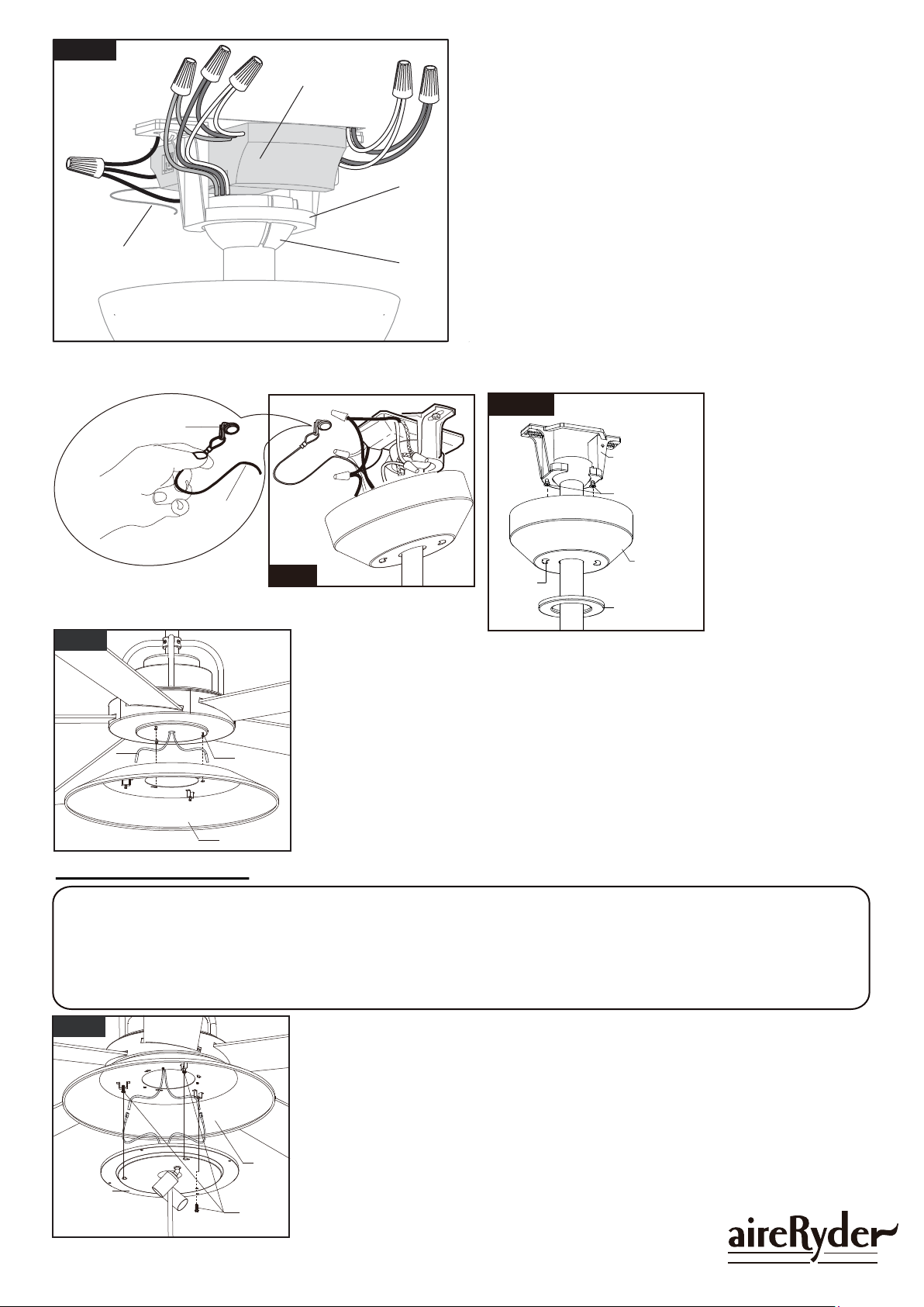
Fig.14
F A N C O
181008
Canopy Screw
Key Hole
Slot
Hanger Bracket
Canopy
Decorative Cap
Push the canopy
upwards by inserting
canopy screw heads in
hanger bracket into key
hole slots, rotate the
canopy, finally, tighten
the canopy screws.
Attach the decorative
cap to canopy, rotate it
clockwise until tight.
Fig.13
Hang the safety cable into the safety cable hook.
Safety Cable Hook
Safety
Cable
Fig.15
Metal Cover
Set Screw
Wire
Thread the wires through the hole of the metal cover, push the metal
cover to the motor by inserting set screw heads at the bottom of the
motor into key hole slots, rotate the metal cover, finally, tighten the
set screws.
Fig.12
Hanger
Bracket
Hanger
Ball
Receiver
1.
4.
5.
6.
2.3.
Antenna:
DO NOT CUT
OR SPLICE
Connect wires:
1) The white (neutral) wire from motor to the white (neutral)
"To Motor N" wire from Receiver with a wire connector.
2) The black (hot) wire from motor to the black (hot) "To
Motor L" wire from Receiver with a wire connector.
3) The blue wire from motor to the blue "For Light" wire from
Receiver with a wire connector.
4) The white (neutral) wire from Outlet Box to the white "AC
in N" wire from Receiver with a wire connector.
5) The black (hot) wire from Outlet Box to the black "AC in L"
wire from Receiver with a wire connector.
6) The ground wire from Outlet Box to the green ground wire
from the Hanger Ball and the green ground wire from the
Hanger Bracket with a wire connector.
Make sure all of wire connectors are connected firmly.
*** Put all wire connectors and wires carefully up into the
outlet box, EXCEPT antenna, which should remain outside
outlet box.
Make wire connection. Plug the connector with black motor wire into the connector
with black light wire. Plug the connector with white motor wire into the connector
with white light wire.
Carefully put the wires into the light kit.
Remove one light kit screw (for later use), then push the light kit to the motor
bottom by inserting light kit screw heads into key hole slots, rotate the light kit,
finally, secure the light kit to metal cover with previous light kit screw and tighten
the other light kit screws.
Fig.16
Metal
Cover
Light Kit
Light Kit
Screw
Fan Light Installation:
WARNING:
As per EPACT 2005 requirements, this fan light has a built-in current limiting device to conserve
energy. The fan light will not operate if the combined wattage of the installed bulbs exceeds 190
Watts. If the fan light shuts off shortly after being switched on, it may be due to excessive current
demand. You should replace the light bulbs with lower wattage bulbs.
Loading ...
Loading ...
Loading ...