Loading ...
Loading ...
Loading ...
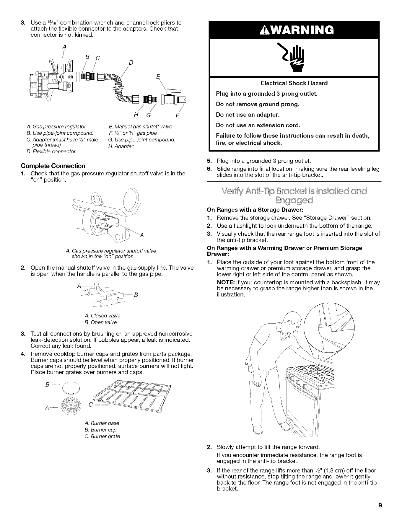
3.
Use
ate"
combination
wrench
and
channel
lock
pliers
to
attach
the
flexible
connector
to
the
adapters.
Check
that
connector
is
not
kinked.
AWAR
A
i
A
c
E
\
Electrical
Shock
Hazard
ic
Plug
into
a
grounded
3
prong
outlet.
J
7
Do
not
remove
ground
prong.
fe,
/
H
G
F
Do
not
use
an
adapter.
A.
Gas
pressure
regulator
E.
Manual
gas shutoff
valve
Do
not
use
an
extension
cord.
B.
Use
pipe-joint
compound.
F.
ie"
or
“A"
gas
pipe
Failure
to
follow
these
instructions
can
result
in
death,
C.
Adapter
(must
have
2"
male
G.
Use
pipe-joint
compound.
fire.
or
electrical
shock
pipe
thread)
H.
Adapter
, .
D.
Flexible
connector
.
5.
Plug
into
a
grounded
3
prong
outlet.
Complete
Connection
a
6.
Slide
range
into
final
location,
making
sure
the
rear
leveling
leg
1.
Check
that
the
gas
pressure
regulator
shutoff
valve
is in
the
slides
into
the
slot
of
the
anti-tip
bracket.
“on” position.
Verify
Anti-Tip
Bracket
is
Installed
and
Engaged
On
Ranges
with
a
Storage
Drawer:
1.
Remove
the
storage
drawer.
See
“Storage
Drawer”
section.
2.
Use
a
flashlight
to
look
underneath
the
bottom
of
the
range.
3.
Visually
check
that
the
rear
range
foot
is
inserted
into
the
slot
of
the
anti-tip
bracket.
A.
Gas
pressure
regulator
shutoff
valve
bn
Ranges
with
a
Warming
Drawer
or
Premium
Storage
shown
in
the
“on”
position
rawer:
1.
Place
the
outside
of
your
foot
against
the
bottom
front
of
the
2.
Open
the
manual
shutoff
valve
in
the
gas
supply
line.
The
valve
warming
drawer
or
premium
storage
drawer,
and
grasp
the
is
open
when
the
handle
is
parallel
to
the
gas
pipe.
lower
right
or
left
side
of
the
control
panel
as
shown.
NOTE:
If
your
countertop
is
mounted
with
a
backsplash,
it
may
—
be
necessary
to
grasp
the
range
higher
than
is
shown
in
the
-
Ven
-B
illustration.
A.
Closed
valve
B.
Open
valve
3.
Test
all
connections
by
brushing
on
an
approved
noncorrosive
leak-detection
solution.
If
bubbles
appear,
a
leak
is
indicated.
Correct
any
leak
found.
4.
Remove
cooktop
burner
caps
and
grates
from
parts
package.
Burner
caps
should
be
level
when
properly
positioned.
If
burner
caps
are
not
properly
positioned,
surface
burners
will
not
light.
Place
burner
grates
over
burners
and
caps.
A.
Burner
base
B.
Burner
cap
C.
Burner
grate
2.
Slowly
attempt
to
tilt
the
range
forward.
If
you
encounter
immediate
resistance,
the
range
foot
is
engaged
in
the
anti-tip
bracket.
3.
If
the
rear
of
the
range
lifts
more
than
2"
(1.3
cm)
off
the
floor
without
resistance,
stop
tilting
the
range
and lower
it
gently
back
to
the
floor.
The
range
foot
is
not
engaged
in
the
anti-tip
bracket.
Loading ...
Loading ...
Loading ...