Loading ...
Loading ...
Loading ...
INSTALLATION
INSTRUCTIONS
NDC
ckRan
1ige
Pe
Excessive
Weight
Hazard
Use
two
or
more
people
to
move
and
install
range.
Failure
to
do
so
can
result
in
back
or
other
injury.
1.
Remove
shipping
materials,
tape
and
film
from
range.
2.
Remove
oven
racks
and
parts
package
from
inside
oven.
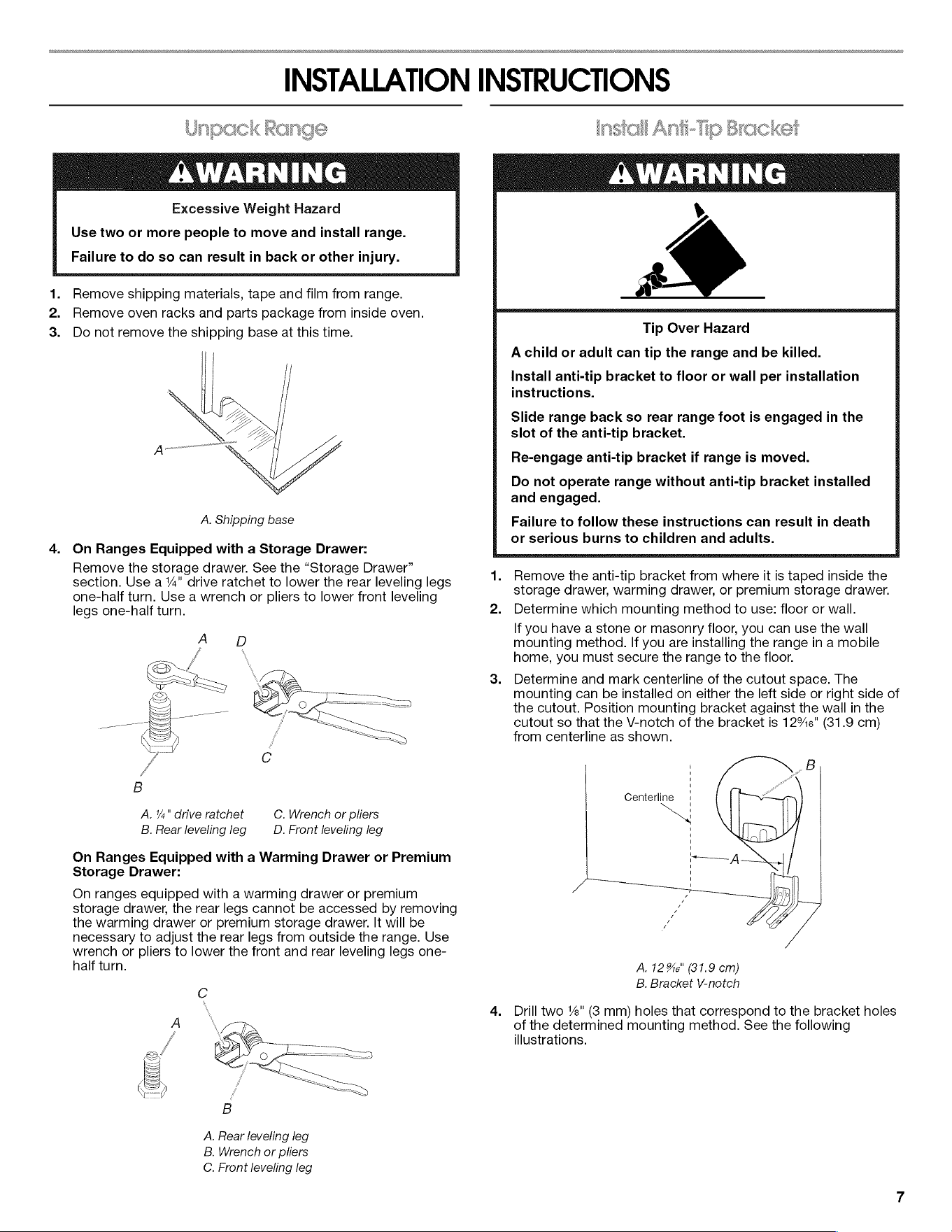
3.
Do
not
remove
the
shipping
base
at
this
time.
A.
Shipping
base
4.
On
Ranges
Equipped
with
a
Storage
Drawer:
Remove
the
storage
drawer.
See
the
“Storage
Drawer”
section.
Use
a
%"
drive
ratchet
to
lower
the
rear
leveling
legs
one-half
turn.
Use
a
wrench
or
pliers
to
lower
front
leveling
legs
one-half
turn.
A.
¥s"
drive
ratchet
B.
Rear
leveling
leg
C.
Wrench
or
pliers
D.
Front
leveling
leg
On
Ranges
Equipped
with
a
Warming
Drawer
or
Premium
Storage
Drawer:
On
ranges
equipped
with
a
warming
drawer
or
premium
storage
drawer,
the
rear
legs
cannot
be
accessed
by
removing
the
warming
drawer
or
premium
storage
drawer.
It
will
be
necessary
to
adjust
the
rear
legs
from
outside
the
range.
Use
wrench
or
pliers
to
lower
the
front
and
rear
leveling
legs
one-
half
turn.
A.
Rear
leveling
leg
B.
Wrench
or
pliers
C.
Front
leveling
leg
—
—
2s
Ss
oa
ef
ae
sone
Anii-Tip
Bracket
AWARNING
v
a
Tip
Over
Hazard
A
child
or
adult
can
tip
the
range
and
be
killed.
Install
anti-tip
bracket
to
floor
or
wall
per
installation
instructions.
Slide
range
back
so
rear
range
foot
is
engaged
in
the
slot
of
the
anti-tip
bracket.
Re-engage
anti-tip
bracket
if
range
is
moved.
Do
not
operate
range
without
anti-tip
bracket
installed
and
engaged.
Failure
to
follow
these
instructions
can
result
in
death
or
serious
burns
to
children
and
adults.
1.
Remove
the
anti-tip
bracket
from
where
it
is
taped
inside
the
storage
drawer,
warming
drawer,
or
premium
storage
drawer.
2.
Determine
which
mounting
method
to
use:
floor
or
wall.
If
you
have
a
stone
or
masonry
floor,
you
can use
the
wall
mounting
method.
If
you
are
installing
the
range
in
a
mobile
home,
you
must
secure
the
range
to
the
floor.
3.
Determine
and
mark
centerline
of
the
cutout
space.
The
mounting
can
be
installed
on
either
the
left
side
or
right
side
of
the
cutout.
Position
mounting
bracket
against
the
wall
in
the
cutout
so
that
the
V-notch
of
the
bracket
is
12%6"
(31.9
cm)
from
centerline
as
shown.
Centerline
A.
12
%s"
(31.9
cm)
B.
Bracket
V-notch
4.
Drill
two
%"
(8
mm)
holes
that
correspond
to
the
bracket
holes
of
the
determined
mounting
method.
See
the
following
illustrations.
Loading ...
Loading ...
Loading ...