Loading ...
Loading ...
Loading ...
lnstaNmat[on
[] ELECTRICAL CONNECTION
A
WARNING- TO REDUCE THE RISK OF
FIRE, ELECTRICAL SHOCK, AND PERSONAL
INJURY:
DO NOT USE AN EXTENSION CORD OR AN
ADAPTER PLUG WITH THIS APPLIANCL
Dryer must be electrically grounded in accordance with
local codes and ordinances, or in the absence of local
codes, in accordance with the NATIONAL ELECTRI-
CAL CODE, ANSI/NFPA NO. 70.
ELECTRICAL REQUIREMENTS
This applim_ce must be supplied with 120V, 60Hz, and connected
to a properly grounded branch circuit, protected by a 1.5-or 20-
amp circuit breaker or time-delay fltse. If electrical supply provid-
ed does not meet the above specifications, it is recommended that
a licensed electriciml install ml approved outlet.
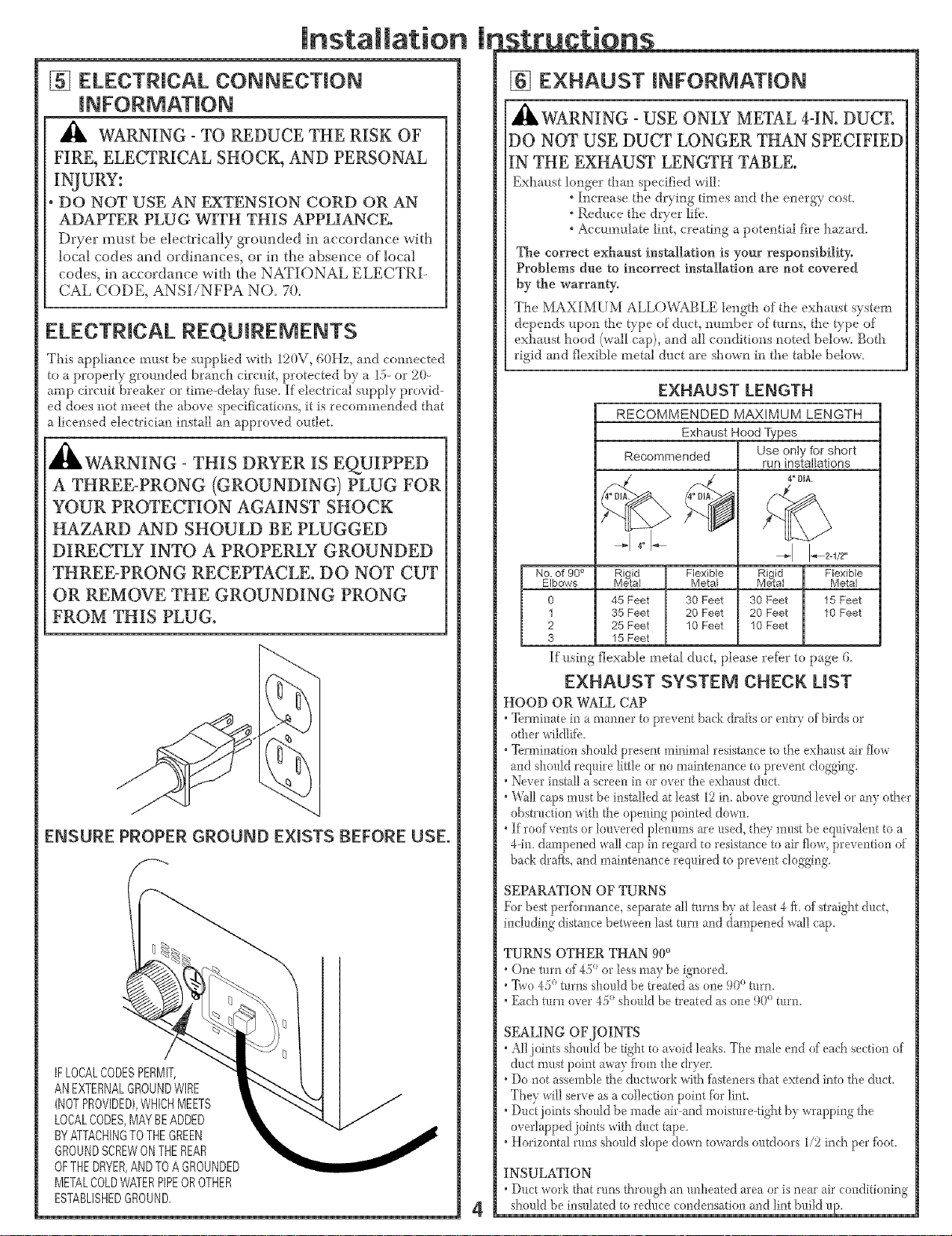
3 - THIS DRYER IS EQUIPPED
A THREE-PRONG (GROUNDING) PLUG FOR
YOUR PROTECTION AGAINST SHOCK
HAZARD AND SHOULD BE PLUGGED
DIRECTLY INTO A PROPERLY GROUNDED
THREE-PRONG RECEPTACLE. DO NOT CUT
OR REMOVE THE GROUNDING PRONG
FROM THIS PLUG.
ENSURE PROPER GROUND EXISTS BEFORE USE.
(-
IFLOCALCODESPERMIT,
ANEXTERNALGROUNDWIRE
(NOTPROVIDED),WHICHMEETS
LOCALCODES,MAYBEADDED
BYATTACHINGTOTHEGREEN
GROUNDSCREWONTHEREAR
OFTHEDRYER,ANDTOAGROUNDED
METALCOLDWATERPIPEOROTHER
ESTABLISHEDGRODND,
4
h structions
[] EXHAUST INFORMATION
A
IHLWARNING - USE ONLY METAL 4-IN. DUCT.
DO NOT USE DUCT LONGER THAN SPECIFIED
IN THE EXHAUST LENGTH TABLE.
Exhm_st longer thml specified will:
° Increase the drying times mid the energy cost.
° Reduce the dryer life.
° Accumulate lint, creattag a potential fire hazard.
The correct exhaust installation is your responsibility,
Problems due to incorrect installation are not covered
by the warranty.
The MAXIMUM ALLOWABLE length of the exhmlst system
depends _lpon the type of duct, number of turns, the type of
exhmlst hood (wall cap), and all conditions noted below. Both
rigid and flexible metal duct are shown in the table below.
EXHAUST LENGTH
RECOMMENDED MAXIMUM LENGTH
Exhaust Hood Types
Recommended
No. of 90 ° Rigid Flexible
Elbows Metal Metal
0 45 Feet 30 Feet
1 35 Feet 20 Feet
2 25 Feet 10 Feet
3 15 Feet
Use only for short
run installations
4" OIA,
;b
Rigid Flexible
Metal Metal
30 Feet 15 Feet
20 Feet 10 Feet
10 Feet
If ustag flexable metal duct, please refbr to page 6
EXHAUST SYSTEM CHECK LIST
HOOD OR WALL CAP
"_rminate in a rnanner to prevent back drafts or entry of birds or
other wildlii_.
•Termination should present minimal resistance to the exlmust air flow
and should require little or no maintenance to prevent clogging.
•Never install a screen in or over the exhaust duct.
°W_ll caps m!_stbe installed at least 12in. above ground level or any other
obstruction with the opening pointed down.
°If roof vents or louvered pMmms are used, they must be eql_ivalent to a
44n. dampened wall cap in regard to resistance to air flow, prevention of
back drafts, and maintenance required to prevent cloggtag.
SEPARATION OF TURNS
For best perfbrmance, separate all turns by at least 4 ft. of straight d!_ct,
including distance between last turn and dampened wail cap.
TURNS OTHER THAN 90°
• One turn of 45° or less may be ignored.
o
°_ivo 45 turns should be treated as one 90° turn.
( O
( • , _(/°Each turn _.ei k should be treated as one 90 turn.
SEALING OF JOINTS
•All joints stlould be tight to avoid leaks. The male end of each section of
duct must point away fi'om the dryer.
•Do not assemble the ductwork with fbsteners that extend into the duct.
They will serve as a collection point tbr lint.
•Duct joints sho_fldbe made air-and moismre4ight by wrapping the
overlapped joints with duct tape.
•Horizontal runs should slope down towards outdoors 1/2 inch pet' tbot.
INSULATION
•Duct work that runs through an unheated area or is neat' air conditioning
should be insulated to re&_ce condensation and lint bldld l_p.
Loading ...
Loading ...
Loading ...