
Loading ...
Loading ...
Loading ...
36
Single Zone Art Cool Premier Wall Mounted Installation Manual
Due to our policy of continuous product innovation, some specifications may change without notification.
©LG Electronics U.S.A., Inc., Englewood Cliffs, NJ. All rights reserved. “LG” is a registered trademark of LG Corp.
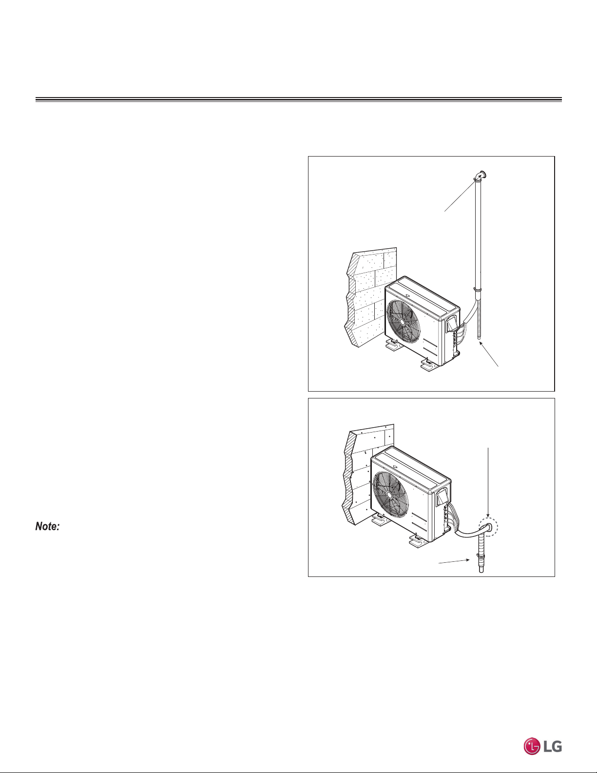
REFRIGERANT PIPING CONNECTIONS
Special Applications
If an additional drain hose is necessary, the end of drain outlet must
be routed above the ground. Secure the drain hose appropriately.
See pages later in this section for information on indoor unit drain
hoses.
When the Outdoor Unit is Installed Below the Indoor Unit:
1. Use a piping set cover, or bundle the (separately) insulated
refrigerant piping, the drain hose, and the communications / con-
nection (power) cable together.
2. Make sure to include some slack in the wiring. Wiring must be
installed in an upwards direction to prevent water from accessing
the control box.
3. Secure the piping set cover or bundle along the outside wall us-
ing saddles or a similar type of piping support.
4. Seal any openings in the wall that are around the piping.
When the Outdoor Unit is Installed Above the Indoor Unit:
1. Use a piping set cover, or bundle the (separately) insulated
refrigerant piping and the communications / connection (power)
cable together up to the outdoor unit service valves.
2. Make sure to include some slack in the wiring. Wiring must be
installed in upwards direction to prevent water from accessing the
control box.
3. If necessary, secure the piping set cover or bundle along the
outside wall using saddles or a similar type of piping support.
4. Ensure the drain hose from the indoor unit is installed away
from the outdoor unit, and in a downward direction. If necessary,
secure along the outside wall using saddles or a similar type of
support.
5. Seal any openings in the wall that are around the piping.
Special Applications
Figure 32: Special Applications. (For Illustrative Purposes. Appear-
ance and Connection Locations Will Differ Depending On Outdoor Unit
Model.)
For information about bundling, see the Bundling page in this section.
For information about using a conduit to protect the wiring between the
outdoor unit and the indoor unit, see the in the Electrical System Instal-
lation section.
Seal the small access hole
in the wall around the piping.
Outdoor Unit Below Indoor Units
Outdoor Unit Above Indoor Units
Seal the small access hole
in the wall around the piping.
Drainage from the Indoor Units
Drainage from the Indoor Units
Loading ...
Loading ...
Loading ...