Loading ...
Loading ...
Loading ...
3.
If the insert is BELOW the table surface, remove the
insert and bend the tabs (with pliers) enough to make
the insert ABOVE the table surface.
4. Re-install insert and adjust asdescribed under "2".
DO NOT TIGHTEN SCREW TO THE POINT WHERE IT
DEFLECTS THE INSERT.
CHECKING BLADE SQUARENESS TO TABLE
IMPORTANT: BLADE must be SQUARE (90 ° ) to
TABLE, in order to proceed with assembly.
1. Turn ELEVATION crank counterclockwise until blade
is up as high as it will go.
2. Check for BLADE SQUARENESS . . . if blade is not
square to table, adjust it at this time.
NOTE: The Combination Square must be "TRUE"-
See start of "Unpacking and Checking Contents section
on page6 for checking method.
Refer to "BLADE TILT, OR SQUARENESS OF
BLADE TO TABLE" adjustments on page 24.
CHECKING BLADE ELEVATION
Maximum depth of cut MUST NOT EXCEED TWO AND
ONE HALF (2-1/2) INCHES. This adjustment is set at the
factory and should be checked to make sure that it has not
changed due to rough handling during shipment.
With the blade up as high as it will go, measure the distance
from the top of the table to top of the highest saw tooth. If
it is more than two inches, adjust it at this time. Refer to
"BLADE ELEVATION" adjustments on page 26.
\
I MAKE SURE SQUARE
IS NOT TOUCHING
F TOOTH
\ "_ \
N
\
ATTACHI NG TABLE EXTEN SIONS
If you received two Table Extensions with your saw
(furnished with Model No. 113.295820) attach them at this
time.
1. Position saw upside down on floor.
NOTE: To protect the finished surfaces of the saw and
extensions, lay a piece of heavy paper on the floor.
2.
3.
4.
From among the loose parts find the following
hardware:
6 Hex Head Screws 5/16.- 18 x 1 in. long
6 Lockwashers, 5/16 in. External Type
(approx. dia. of hole 5/16 in.)
6 Flat Washers (dia. of hole 11/32 in.)
6 Hex Nuts, 5/16 in. 18 (approx. dia. of hole 5/16
in.)
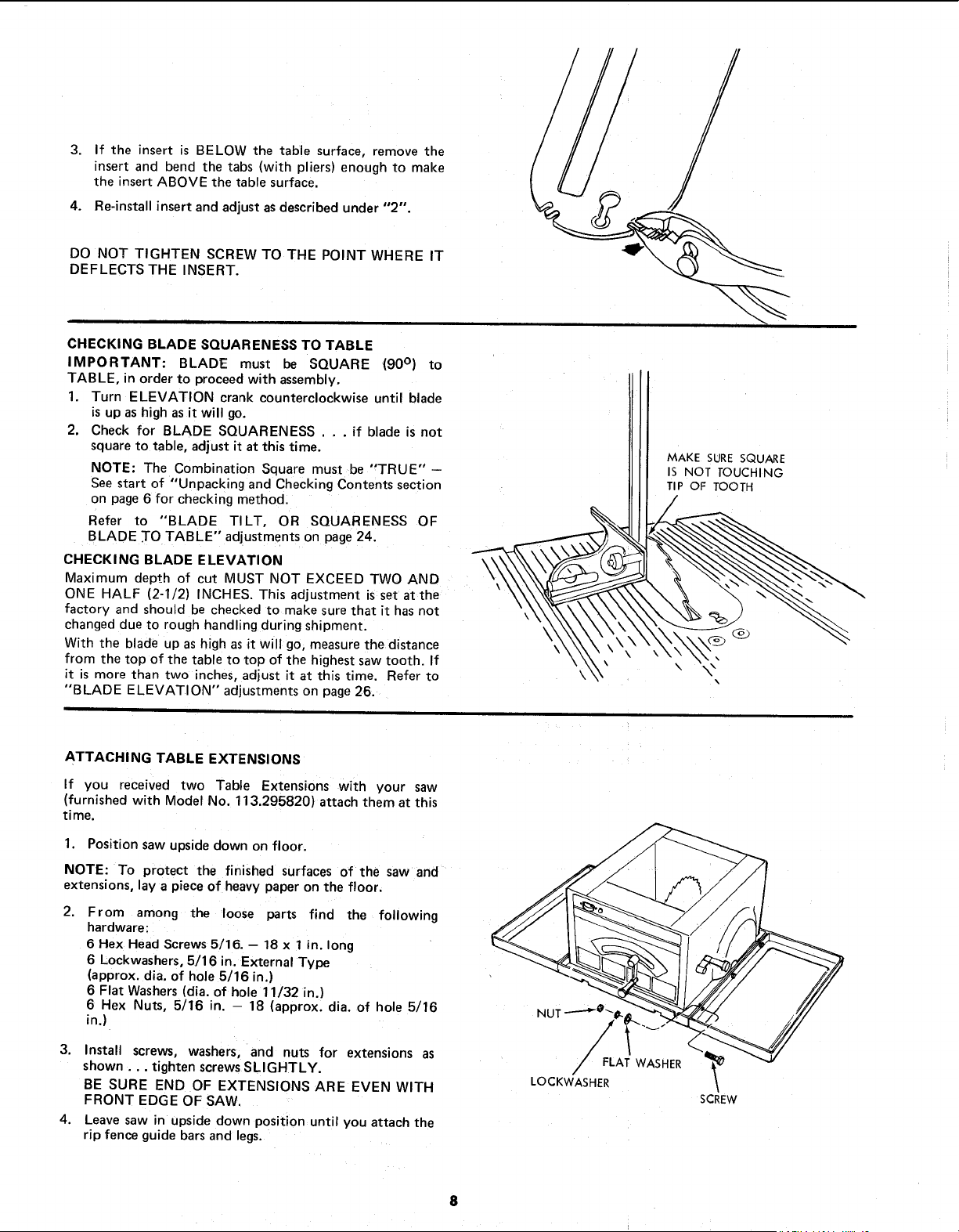
Install screws, washers, and nuts for extensions as
shown.., tighten screws SLIGHTLY.
BE SURE END OF EXTENSIONS ARE EVEN WITH
FRONT EDGE OF SAW.
Leave saw in upside down position until you attach the
rip fence guide bars and legs.
FLAT WASHER
/
LOCKWASHER
SCREW
8
Loading ...
Loading ...
Loading ...