
READ AND FOLLOW ALL SAFETY AND
OPERATING INSTRUCTIONS BEFORE USING THIS SAW.
LEA Y SIGA TODAS LAS INSTRUCCIONES
DE FUNCIONAMIENTO Y SEGURIDAD ANTES DE USAR ESTA SIERRA.
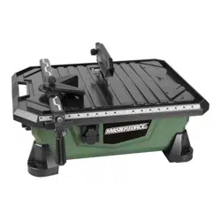
7" 1HP WET SAW
OWNER’S MANUAL
SIERRA ELÉCTRICA DE 1HP PARA CORTAR
LOSETAS
DE 180MM
MANUAL DE OPERACIÓN
709-3954
E200561
WET TILE SAW
29FG

GARANTIA LIMITADA A TRES AÑOS:
Si durante su uso normal, esta herramienta MASTERFORCE
®
se daña o falla dado a un defecto en el material o en su
fabricación, dentro de los (3) años desde la fecha original de compra, simplemente traiga la herramienta y su recibo
original de compra a algunos de nuestros almacenes cercanos de MENARDS
®
. Bajo su discreción MASTERFORCE
®
está
de acuerdo en reparar o reemplazar la herramienta o una parte defectuosa dentro del periodo de garantida estipulado,
cuando sea regresada por el comprador original y con el recibo de compra original. Esta garantía:(1) excluye a las partes
sujetas a un desgaste usual, (2) se anulará la garantía si utiliza la herramienta para un uso comercial y para ser rentada;
y (3) no se cubren perdidas, lesiones a personas o a propiedades ni a sus costos. Esta garantía sí le da derechos legales
específicos y usted podría tener otros derechos, los cuales varían de Estado a Estado.
THREE-YEAR LIMITED WARRANTY:
If, during normal use, this MASTERFORCE
®
power tool breaks or fails due to a defect in material or workmanship within
three (3) years from the date of original purchase, simply bring this tool with the original sales receipt back to your nearest
MENARDS
®
retail store. At its discretion, MASTERFORCE
®
agrees to have the tool or any defective part (s) repaired or
replaced with the same or similar MASTERFORCE
®
product or part free of charge, within the stated warranty period, when
returned by the original purchaser with the original sales receipt. This warranty; (1) excludes expendable parts; (2) shall be
void if this tool is used for commercial and/or retail purposes; and (3) does not cover any losses, injuries to persons/property
or costs. This warranty does give you specific legal rights and you may have other rights, which vary from state to state.

– 1 –
TABLE OF CONTENTS
General safety instructions................1
Warning ................................2
Electrical requirements . . . . . . . . . . . . . . . . . . . 3
Extension cords.......................... 3
California Proposition 65 ..................4
Description.............................. 4
Assembly ..............................5-7
Operation ..............................7-8
Maintenance . . . . . . . . . . . . . . . . . . . . . . . . . . . . 9
Troubleshooting..........................9
Parts list ...............................10
Exploded parts diagram..................11
GENERAL SAFETY
INSTRUCTIONS
READ THIS OWNER'S
MANUAL COMPLETELY AND MAKE
SURE YOU UNDERSTAND ALL OF ITS
SAFETY GUIDELINES.
1. KEEP GUARDS IN PLACE and in
working order.
2. REMOVE ADJUSTING KEYS AND
WRENCHES. Before turning on the tile saw,
make sure the keys and adjusting wrenches
have been removed.
3. KEEP WORK AREA CLEAN. Cluttered areas
and benches invite accidents.
4. ALWAYS REMAIN ALERT WHEN THE SAW
IS IN USE. Inattention on the part of the
operator may lead to serious injury.
5. DON’T USE IN A DANGEROUS
ENVIRONMENT. Don’t use power tools in
damp or wet locations or expose them to
rain. Keep work area well lit.
6. KEEP CHILDREN AWAY. Anyone in the
cutting vicinity should remain at a safe
distance from work area.
7. MAKE WORKSHOP CHILD-PROOF with
padlocks, master switches or by removing
starter keys.
8. USE THE RIGHT TOOL. Don’t use a tool or
attachment to do a job for which it was
not designed.
9. USE THE PROPER EXTENSION CORD.
Make sure your extension cord is in good
condition. When using an extension cord,
be sure to use one heavy enough to carry
the current your product will draw. An
undersized cord will cause a drop in line
voltage resulting in loss of power and
overheating. TABLE 1 (page 4) shows the
correct size to use depending on cord
length and nameplate ampere rating. If
in doubt, use the next heavier gauge. The
smaller the gauge number, the heavier
the cord.
10. DON’T FORCE THE TOOL. It has been
designed to operate at maximum safety and
performance levels.
11. DO NOT FORCE THE MATERIAL BEING CUT.
Always let the blade cut at its own speed.
12. WEAR PROPER APPAREL. Do not wear
loose clothing, neckties, rings, bracelets
or other jewelry which may get caught
in moving parts. Non-slip foot wear is
recommended. Wear protective hair
covering if you have long hair.
13. ALWAYS USE SAFETY GLASSES. Also use
face or dust mask for commercial cutting
operations. Everyday eyeglasses only have
impact-resistant lenses, they are NOT
safety glasses.
14. DON’T OVERREACH. Keep proper footing
and balance at all times.
15. MAINTAIN TOOLS WITH CARE. Keep tools
clean and in good working condition for
maximum safety performance.
16. DISCONNECT SAW BEFORE SERVICING
– when changing accessories, such as
blades, bits, cutters, etc.
7" 1HP WET SAW
OWNER’S MANUAL
– 2 –
17. REDUCE THE RISK OF UNINTENTIONAL
STARTING. Make sure switch is in OFF
position before plugging in.
18. USE RECOMMENDED ACCESSORIES.
Consult the owner’s manual for
recommended accessories. The use of
improper accessories may increase risk of
injury.
19. DO NOT DRY CUT WITH BLADES
DESIGNED FOR WET CUTS.
20. Make sure you USE THE CORRECT BLADE
for the type of material that is being cut.
21. NEVER STAND ON TOOL. Serious injury
could occur if the wet saw is tipped or if the
cutting tool is unintentionally contacted.
22. CHECK DAMAGED PARTS. Before further
use of the tool, damaged part(s), (i.e.,
guard) should be carefully checked to
determine that it will operate properly
and perform its intended function. Check
for alignment of moving parts, binding of
moving parts, breakage of parts, mounting
and any other condition that may affect the
saw’s operation. A guard or other part that
is damaged should be properly repaired
or replaced.
23. Ensure that BLADE IS TRAVELING
THROUGH WATER RESERVOIR FOR WET
CUTTING.
24. CHECK DIAMOND BLADES carefully for
cracks, nicks, missing diamond matrix
or out-of-alignment condition. Replace
damaged blades immediately. DO NOT
USE DAMAGED BLADES. They may cause
bodily injury.
25. DIRECTION OF FEED. Feed work into the
blade against the direction of rotation of
the blade only.
26. DO NOT ALTER THE PLUG or use a 2-prong
receptacle. This saw is equipped with a
3-prong electrical plug.
27. NEVER LEAVE SAW RUNNING
UNATTENDED. Turn power off. Don’t leave
tool until it comes to a complete stop.
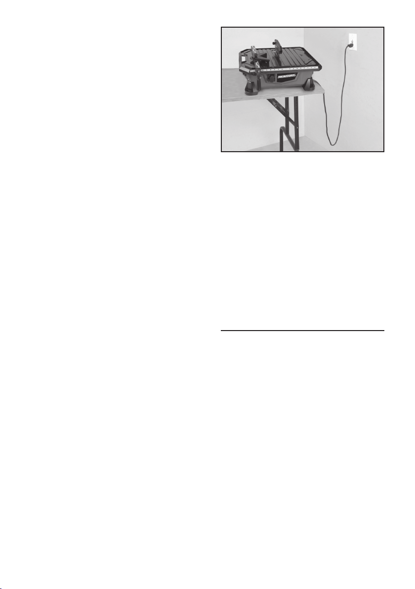
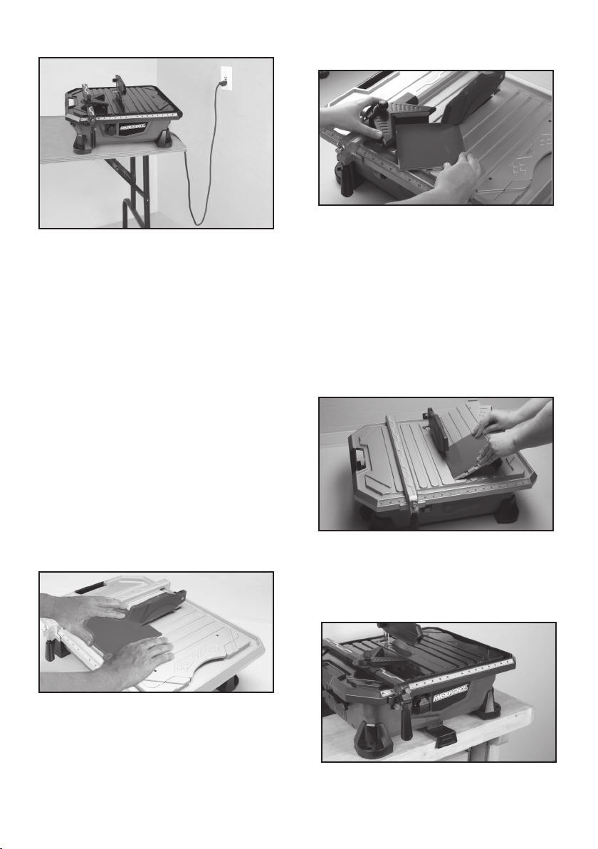
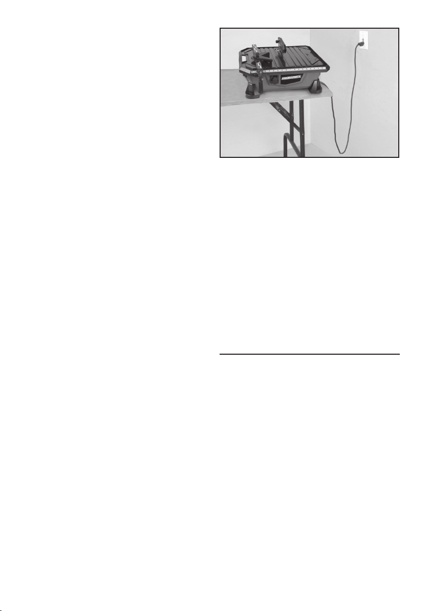
28. POSITIONING OF TILE SAW (see FIGURE 1)
FIGURE 1
• To avoid the possibility of the appliance plug
or receptacle getting wet, position the tile
saw to one side of a wall-mounted receptacle
to prevent water from dripping onto the
receptacle or plug. The user should arrange
a “drip loop” in the cord connecting the saw
to a receptacle. The “drip loop” is that part
of the cord below the level of the receptacle,
or connector if an extension cord is used, to
prevent water traveling along the cord and
coming in contact with the receptacle.
• If the plug or receptacle does get wet, DO
NOT unplug the cord. Disconnect the fuse
or circuit breaker that supplies power to the
tool. Then, unplug and examine for presence
of water in the receptacle.
WARNING
PERSONAL INJURY CAN OCCUR IF OPERATED
IMPROPERLY.
• Keep fingers and loose clothing away from
rotating blade.
• Use extreme caution when cutting tile. Make
sure hands and fingers are clear from the
blade groove in the table. Severe abrasion,
cuts, or pinching of hands or fingers can occur.
• Electrical shock can occur if operating
instructions are not followed.
FOR YOUR OWN SAFETY READ INSTRUCTION
MANUAL BEFORE OPERATING SAW.
• Wear eye protection.
• Use blade guard for every operation for
which it can be used.
• Unplug saw before servicing, when changing
cutting wheels, and cleaning.
– 3 –
• Use tool only with smooth-edge cutting
wheels free of openings and grooves.
• Replace damaged cutting wheel
before operating.
• Do not fill water tray above raised over flow
drain.
ELECTRICAL
REQUIREMENTS
1. THIS TILE SAW MUST BE CONNECTED TO
A GROUNDED POWER SOURCE while in
use to protect the operator from electrical
shock.
2. IN THE EVENT OF A MALFUNCTION OR
BREAKDOWN, grounding provides a path
of least resistance for electrical current
to reduce the risk of electrical shock. This
tile saw is equipped with an electrical
cord with a grounding conductor and
a grounding plug. Insert the 3-prong
electrical plug into a 3-pole receptacle
that is properly installed and grounded
in accordance with all local codes and
ordinances.
3. DO NOT MODIFY THE PLUG provided if it
will not fit the outlet. Have the proper outlet
installed by a qualified electrician.
4. IMPROPER CONNECTION OF THE
EQUIPMENT-GROUNDING CONDUCTOR
CAN RESULT IN A RISK OF ELECTRIC
SHOCK. The conductor with insulation that
is green on the outside (with or without
yellow stripes) is the equipment-grounding
conductor. If repair or replacement of
the electrical cord or plug is necessary,
do not connect the equipment-grounding
conductor to a live terminal.
5. CHECK WITH A QUALIFIED ELECTRICIAN
or service personnel if the grounding
instructions are not completely understood,
or if in doubt as to whether the tool is
properly grounded.
6. USE ONLY 3-WIRE EXTENSION CORDS that
have 3-prong grounding plugs and 3-pole
receptacles that accept the tile saw’s plug.
7. REPAIR OR REPLACE DAMAGED OR WORN
CORD IMMEDIATELY.
8. IF THE PLUG OR RECEPTACLE DOES
GET WET, DO NOT UNPLUG THE CORD.
Disconnect the fuse or circuit breaker that
supplies power to the tool. Then, unplug
and examine for the presence of water in
the receptacle.
9. ONLY UL-LISTED EXTENSION CORDS
SHOULD BE USED WITH THIS PRODUCT.
10. IMPROPER USE OF EXTENSION CORDS
MAY CAUSE INEFFICIENT OPERATION
OF YOUR TOOL, which can result in
overheating. Be sure your extension cord
is rated to allow sufficient current flow to
the motor. For the proper gauge for this tile
saw, please refer to TABLE 1 (page 4).
11. DO NOT LET YOUR FINGERS TOUCH THE
TERMINALS of plug when installing or
removing the plug to or from the outlet.
12. THIS TILE SAW MUST BE PROPERLY
GROUNDED. The risk of electric shock
and bodily injury are greatly increased if
it is not, particularly when used in damp
locations or in proximity to plumbing.
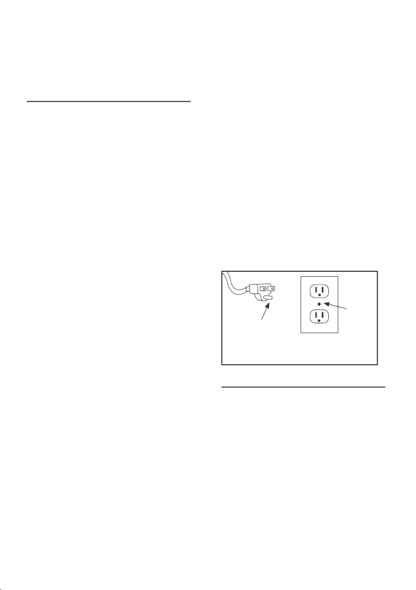
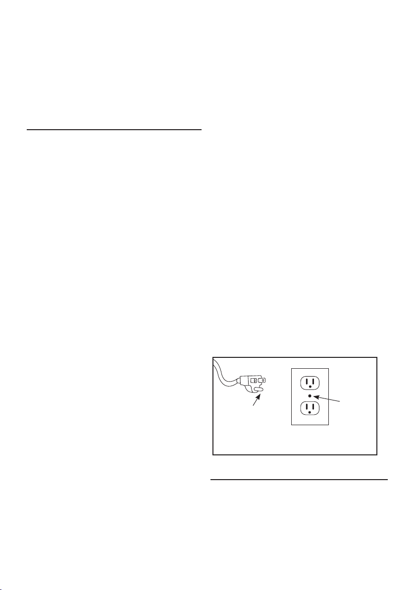
NOTE: This saw is intended for use on
a circuit that has a grounded outlet box
like the one illustrated in FIGURE 2 (B).
This saw has a grounding plug that looks
like the one illustrated in FIGURE 2 (A).
Metal
screw
(B) Grounded
outlet box
(A) Grounding pin
FIGURE 2
EXTENSION CORDS
1. Use only extension cords that are intended
for outdoor use. These extension cords are
identified by a marking “Acceptable for
use with outdoor appliances: store indoors
while not in use.” Use only extension cords
having an electrical rating not less than the
rating of the product. Do not use damaged
extension cords. Examine extension cord
before using and replace if damaged. Do
not abuse extension cords and do not
pull on any cord to disconnect. Keep cord
away from heat and sharp edges. Always
disconnect the extension cord from the
receptacle before disconnecting the product
from the extension cord.

– 4 –
TO REDUCE THE RISK
OF ELECTROCUTION, KEEP ALL CONNECTIONS
DRY AND OFF THE GROUND. DO NOT TOUCH
PLUG WITH WET HANDS.
2. Ground Fault Circuit Interrupter (GFCI)
protection should be provided on the circuit(s)
or outlet(s) to be used for the tile saw.
Receptacles are available having built-in GFCI
protection and may be used for this measure
of safety.
3. USE PROPER EXTENSION CORD. Make
sure your extension cord is in good condition.
When using an extension cord, be sure to use
a cord heavy enough to carry the current your
product will draw. An undersized cord will
cause a drop in line voltage, resulting in a loss
of power and overheating. TABLE 1 shows the
correct size to use depending on cord length
and nameplate ampere rating. If in doubt, use
the next heavier gauge. The smaller the gauge
number, the heavier the cord.
NOTE: When using an extension cord, ensure
all cords are no smaller than #12 gauge, rated
at a 20-amp minimum, and equipped with
3-prong plugs. Use of anything smaller may
result in overheating or burn out of the motor. It
is recommended to have an electrician check
the voltage at the saw motor to ensure proper
voltage to run the saw efficiently and safely.
CALIFORNIA
PROPOSITION 65
SOME DUST CREATED
BY POWER SANDING, SAWING, GRINDING,
DRILLING AND OTHER CONSTRUCTION
ACTIVITIES CONTAIN CHEMICALS KNOWN
TO THE STATE OF CALIFORNIA TO CAUSE
CANCER, BIRTH DEFECTS OR OTHER
REPRODUCTIVE HARM.
Some examples of these chemicals are:
• Lead from lead-based paints
• Crystalline silica from bricks, cement and other
masonry products
• Arsenic and chromium from chemically-treated
lumber
Your risk from these exposures varies, depending
on how often you do this type of work. To reduce
your exposure to these chemicals: work in a well
ventilated area, and work with approved safety
equipment, such as those dust masks that are
specifically designed to filter out microscopic
particles.
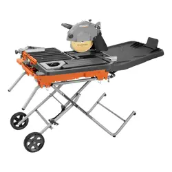
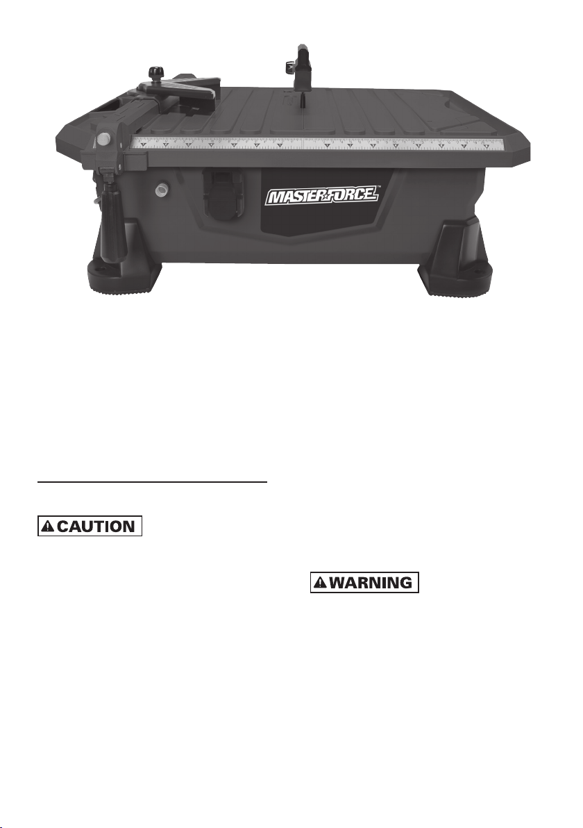
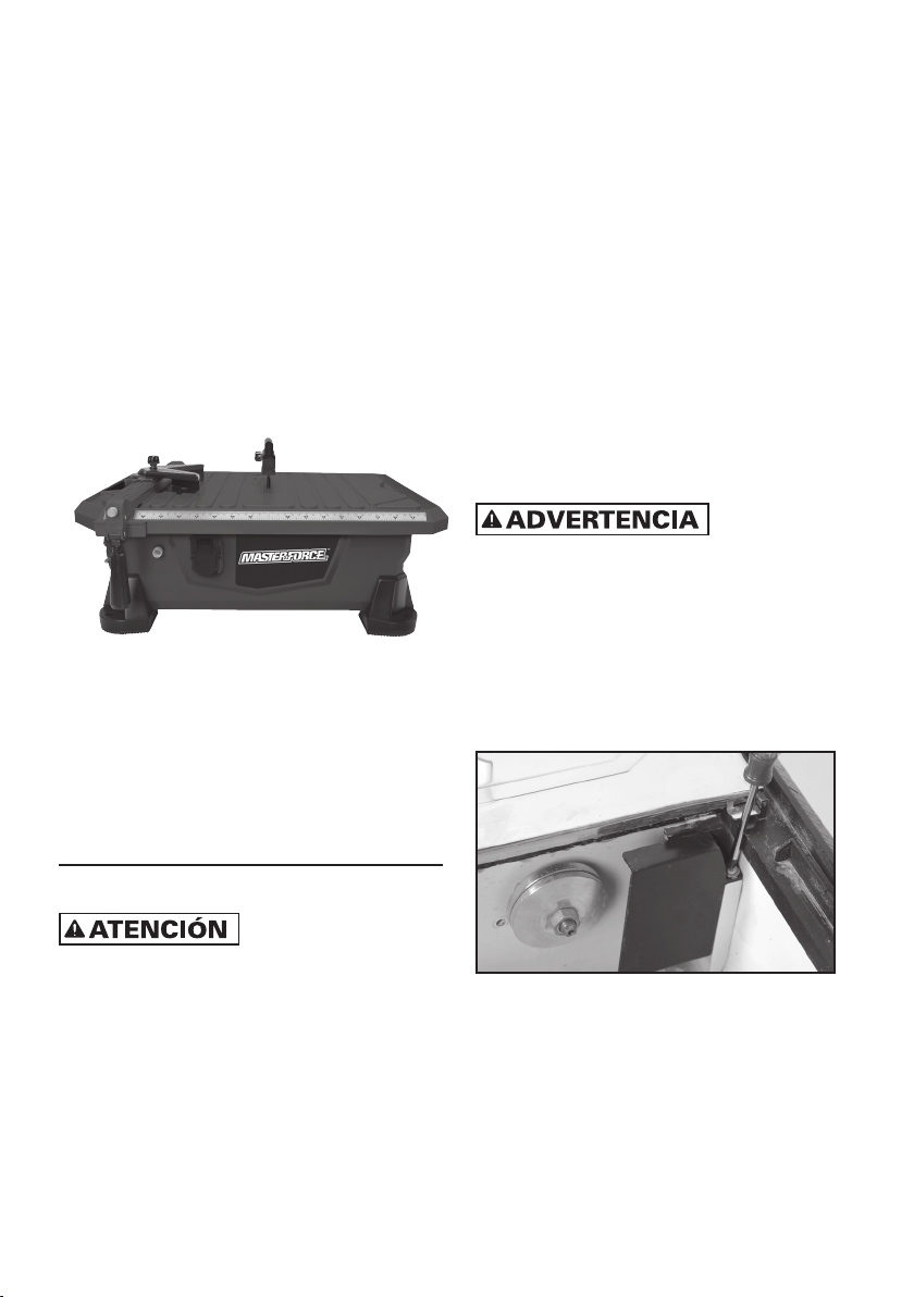
DESCRIPTION
Before attempting to use any tool, be sure to
familiarize yourself with all the operating features
and safety instructions.
KNOW YOUR SAW
Your tile saw has many built-in features for
fast and efficient cutting of ceramic, porcelain,
marble, slate or limestone wall or floor tile. The
durable 7 inch blade cuts tile up to 1-1/8 in. (29
mm) thick. The adjustable rip and angle guides
allow 90° rip cuts and 22.5°or 45° angle cuts on
both the right and left sides. The right cutting
table is hinged so it can be adjusted for 15°, 30°
and 45° miter cuts. The right table has a built-in
water reservoir for cooling the blade.
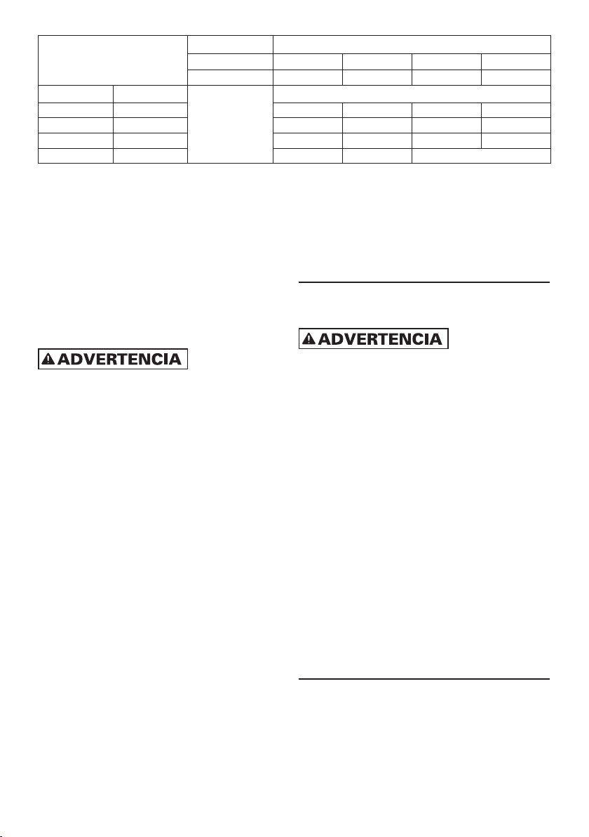
Ampere rating
Volts Total length of cord in feet
120 V 25 ft. 50 ft. 100 ft. 150 ft.
240 V 50 ft. 100 ft. 200 ft. 300 ft.
More than No more than AWG
0 6 18 16 16 14
6 10 18 16 14 12
10 12 16 16 14 12
12 16 14 12 Not recommended
TABLE 1
– 5 –
PRODUCT SPECIFICATIONS
Input: 6.5 Amps
No-load Speed: 3600 RPM
Output: 1-Peak HP
Blade Diameter: 7 in. (180 mm)
Arbor: 5/8 in.
Rating: 120 Volts~60 Hz AC
Depth of Cut: 1-1/8 in. (29 mm)
ASSEMBLY
FOLLOW ALL OF THE
ASSEMBLY AND OPERATION INSTRUCTIONS
COMPLETELY BEFORE CONNECTING THE
SAW TO A POWER SOURCE OR TURNING THE
MOTOR ON.
UNPACKING
1. Remove all packing materials from around
your saw.
2. Carefully lift the saw from carton and place
it on a level work surface.
3. Do not discard the packing materials until
you have carefully inspected the saw for
loose or damaged parts.
The following items are included in box with
your tile saw:
• Tile Wet Saw
• 7 in. Diamond Blade
• Blade guard
• Rip Guide
• Angle Cutting Guide
• Owner’s Manual
4. Inspect the saw carefully to make sure
that no breakage or damage has occurred
during shipping. If any parts are damaged
or missing, please call Customer Service at
866-435-8665
IF ANY PARTS ARE
DAMAGED OR MISSING, DO NOT ATTEMPT
TO OPERATE THIS SAW. OPERATING THIS
SAW WITH DAMAGED OR MISSING PARTS
COULD RESULT IN POSSIBLE SERIOUS
PERSONAL INJURY.
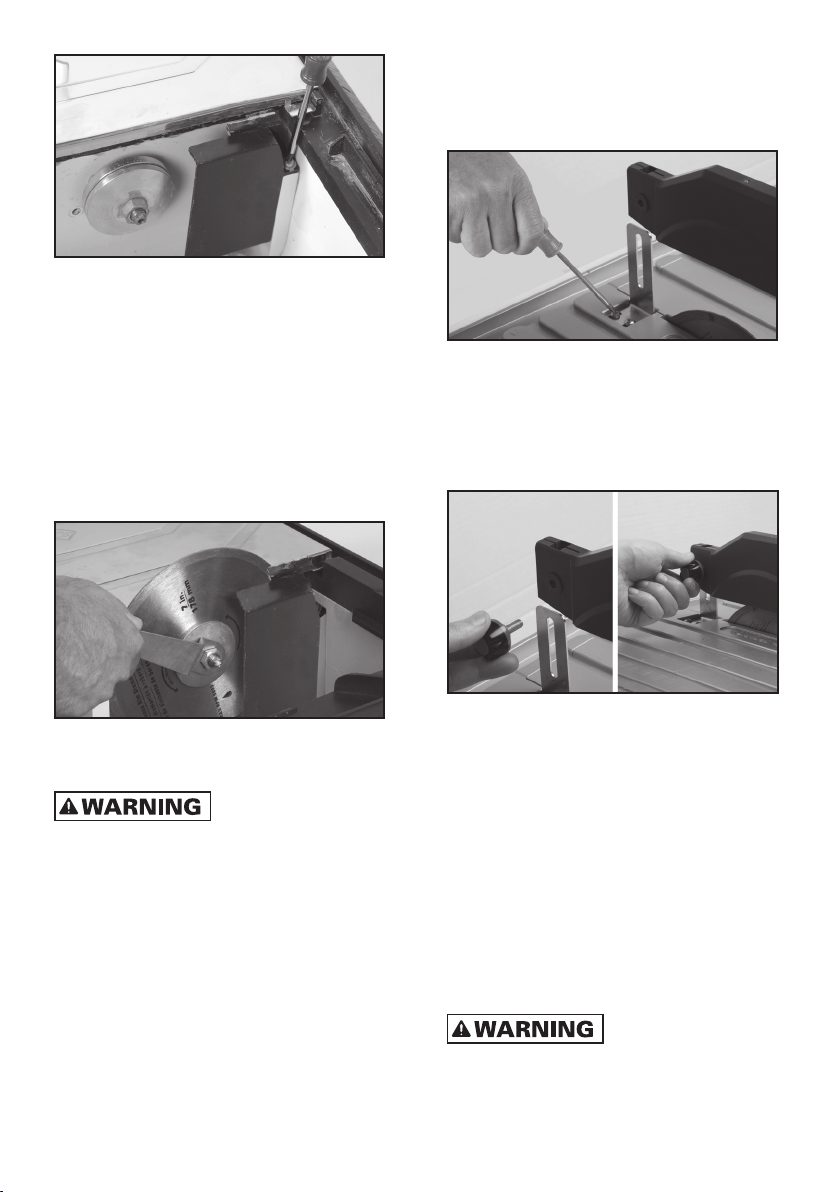
INSTALLING THE BLADE
1. Remove right cutting table.
2. Remove baffle (see FIGURE 4)
FIGURE 3
– 6 –
FIGURE 4
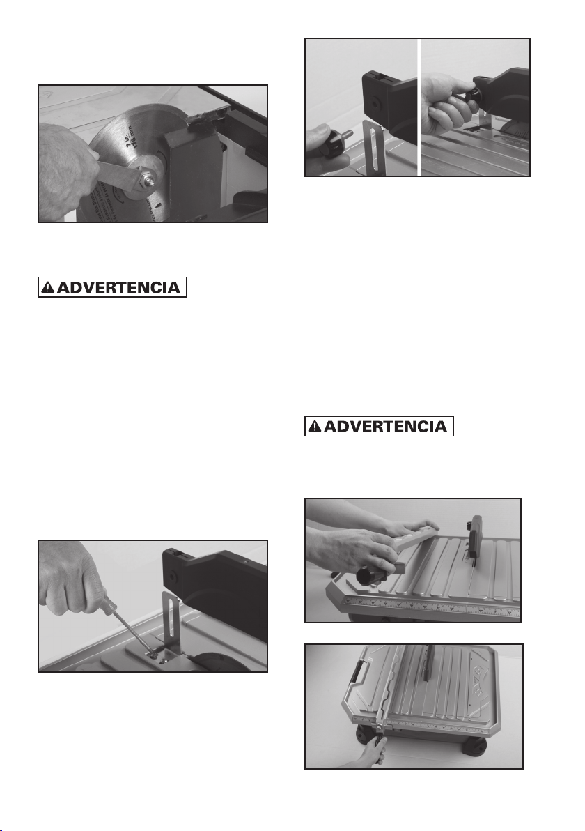
3. Remove blade shaft nut and outer flange.
4. Carefully place the blade onto the shaft and
push it against the inner flange.
5. Be sure the side of the blade with the
directional arrow is facing towards you.
6. Place the outer flange and the blade shaft
nut onto blade.
7. Hold blade and firmly tighten the blade shaft
nut with the included wrench, but do not
over tighten (see FIGURE 5).
FIGURE 5
8. Replace baffle and right cutting table.
USE ONLY
CONTINUOUS RIM BLADES WITH THIS SAW.
DO NOT USE SEGMENTED, “TURBO” BLADES,
WOOD SAWING BLADES, BLADES WITH
OPENINGS, OR ANY OTHER CUTTING DEVICES
WITH THIS TILE SAW. USING THESE BLADES
COULD RESULT IN SERIOUS PERSONAL
INJURY AND DAMAGE TO THE SAW.
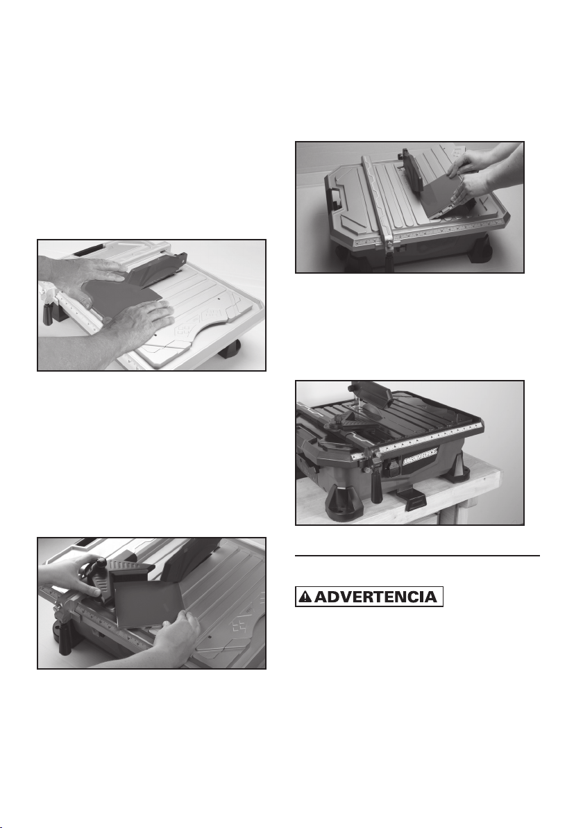
INSTALLING THE BLADE GUARD
1. Remove the 2 screws on top of the table,
behind the blade slot.
2. Insert blade guard support to align with the
holes where the screws were removed. Adjust
the blade guard support so that the support
aligns with the blade.
3. Insert the 2 screws and tighten (see
FIGURE 6).
FIGURE 6
3. Slip the back end of the blade guard down
over the blade guard support (see FIGURE 7).
4. Replace the knob into the blade guard, while
being careful to hold bolt on the right side in
place, then tighten (see FIGURE 7).
FIGURE 7
5. It is suggested that the front of the blade
guard be pointed slightly down to minimize
the front splash during cutting.
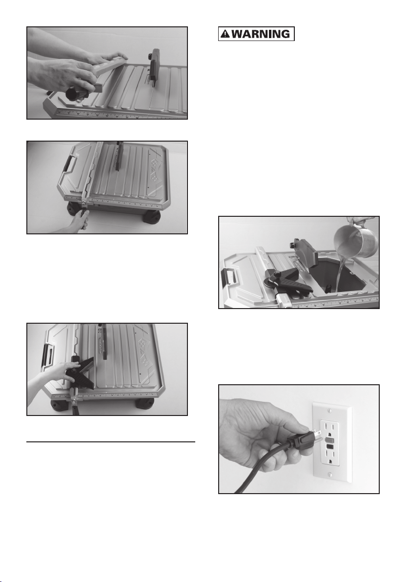
INSTALLING THE RIP GUIDE
1. Slip the back of the rip guide on the back
edge of the table (see FIGURE 8)
2. Place front of rip guide down on the front
edge of the saw.
3. Adjust position to the size of the cut needed,
and flip down lever to lock rip guide in place.
(see FIGURE 9)
4. The round knob over the lever is also used
to further tighten the rip guide.
PINCH POINT.
KEEP HANDS CLEAR OF HINGED LEVER WHEN
LOCKING AND UNLOCKING RIP GUIDE.
– 7 –
FIGURE 8
FIGURE 9
INSTALLING THE ANGLE GUIDE
1. The angle guide is designed to fit on top of the
rip guide. Simply place angle guide onto the
top of the rip guide. (see FIGURE 10)
NOTE: The angle and rip guides can be placed on
either the left or right side.
FIGURE 10
OPERATION
IMPORTANT: ALWAYS turn off the saw and
remove the plug from the outlet BEFORE adding
or removing accessories and making adjust-
ments.
FAILURE TO UNPLUG
THE SAW COULD RESULT IN ACCIDENTAL
STARTING CAUSING POSSIBLE SERIOUS
PERSONAL INJURY.
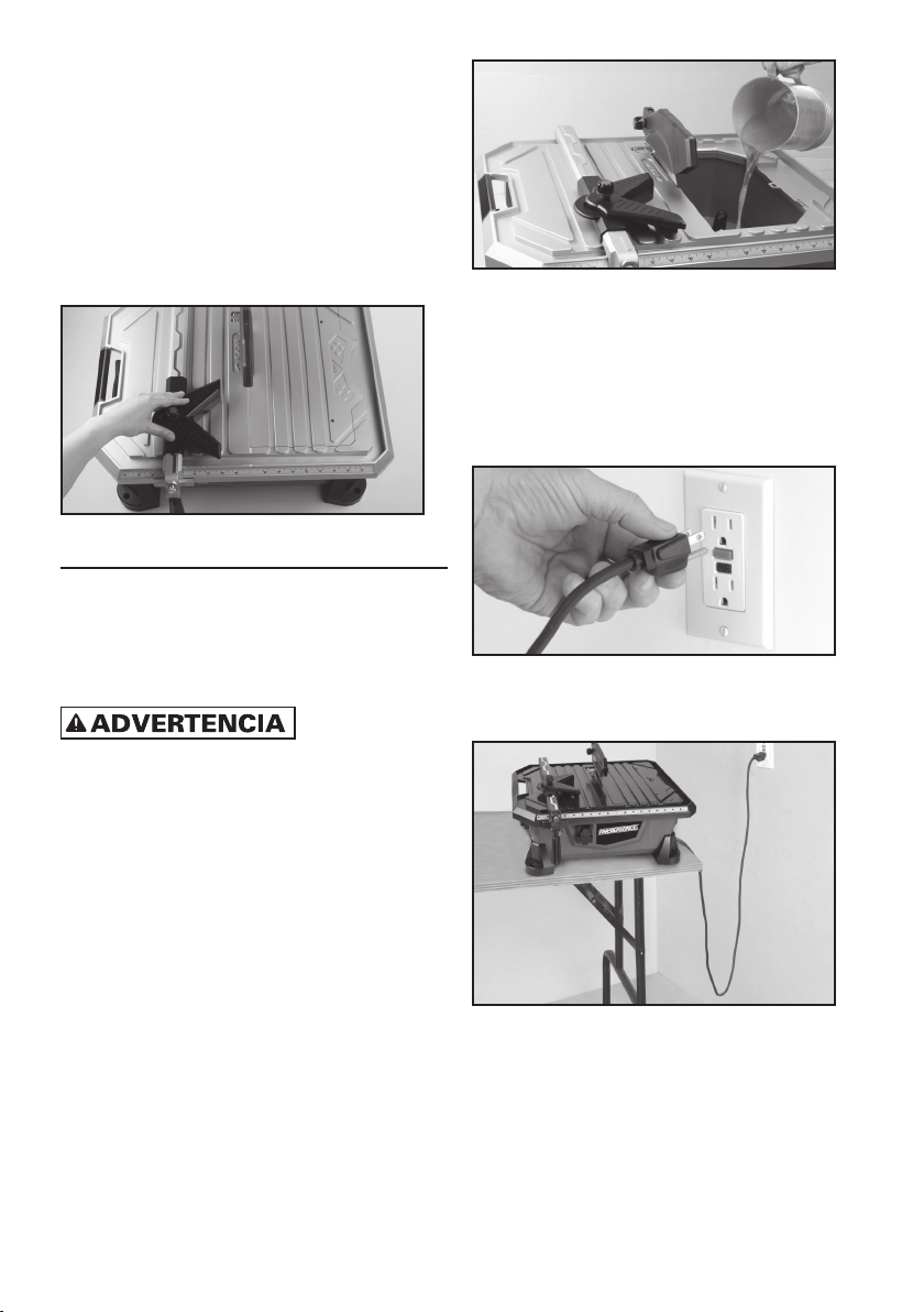
BEFORE STARTING THE SAW
1. Make sure saw is unplugged.
2. Remove the right cutting table, secure the
waterplug and fill the water reservoir to the
fill line (see FIGURE 11). Do not fill above this
level.
NOTE: ALWAYS keep enough water in the
reservoir when operating the saw. DO NOT let
the saw run dry.
3. Re-attach and close right cutting table.
IMPORTANT: ALWAYS completely drain the
water reservoir and clean thoroughly after
each use.
FIGURE 11
TO START THE SAW
1. Remove cord from side compartment and
connect it to a GFCI (Ground Fault Circuit
Interrupter) protected outlet
(See FIGURE 12)
3.Push On/Off switch to the “On” position.
FIGURE 12
– 8 –
2. Create “drip loop” in the cord (see FIGURE 13)
FIGURE 13
MAKING CUTS
The edge of the cutting table has easy-to-see
dimensions (in both inches and centimeters)
for cutting accuracy.
IMPORTANT: ALWAYS LET THE BLADE CUT AT
ITS OWN SPEED. DO NOT FORCE THE MATERIAL
BEING CUT. ALWAYS CHECK THE BLADE FOR
CRACKS OR DAMAGE BEFORE EACH USE.
MAKING 90° RIP CUTS
1. Install the rip guide by placing it at the
desired position according to the width of
the cut you are making.
2. Place the material to be cut against the
rip guide.
3. Carefully and slowly feed the material into
the blade (see FIGURE 14).
4. If necessary, the rip guide can be removed
when cutting large format tile.
FIGURE 14
MAKING 22.5° & 45° ANGLE CUTS
1. Place the angle guide on the top of the
rip guide.
2. Loosen knob. Position guide to desired
angle (22.5° & 45°) and place tile in guide.
3. Carefully push the angle guide and material
towards the blade (see FIGURE 15).
FIGURE 15
MAKING 15°, 30° & 45° MITER CUTS
(see FIGURE 16)
1. The right cutting table can be angled at 15° or
30° or 45°.
2. Two braces under the table unfold to support
the table at the desired angle.
3. Place the material to be cut onto the right
cutting table.
4. Carefully and slowly feed material into the
blade.
FIGURE 16
FOLDING BENCH STOP
(see FIGURE 17)
1. Convenient Bench Stop keeps saw in place
while making cuts.
FIGURE 17

– 9 –
MAINTENANCE
TO AVOID ACCIDENTS,
ALWAYS DISCONNECT THE TOOL FROM
THE POWER SOURCE BEFORE CLEANING OR
PERFORMING ANY MAINTENANCE
Please do not try to service this machine on
your own.
Avoid using solvents when cleaning plastic
parts. Most plastics are susceptible to damage
from various types of commercial solvents
and may be damaged by their use. Use clean
cloths to remove dirt, carbon dust, etc.
DO NOT AT ANY TIME
LET BRAKE FLUIDS, GASOLINE, PETROLEUM-
BASED PRODUCTS, PENETRATING OILS, ETC.
COME IN CONTACT WITH PLASTIC PARTS.
THEY CONTAIN CHEMICALS THAT CAN
DAMAGE, WEAKEN OR DESTROY PLASTIC.
1. ALWAYS clean the tile saw after each use
and store it in a dry location.
2. ALWAYS wipe off all exterior surfaces and
keep the cutting table clean and free of
all debris.
3. ALWAYS check the blade for cracks or
damage BEFORE each use.
4. ALWAYS store the cord in the compartment
underneath the saw after each use.
DIAMOND BLADES
• Use only 7 in. (180 mm) continuous rim
diamond blades with a 5/8" arbor opening in
this saw. Failure to do so may result in severe
bodily injury and damage to the saw.
DIAMOND BLADE DO’S & DON’TS
1. DO inspect blades daily for cracks or uneven
wear. Discard cracked, chipped or bent
blades!
2. DO use manufacturer’s recommendation
for matching the right blade with the right
material being cut.
3. DO inspect the arbor shaft for uneven wear
before mounting the blade.
4. DO use blades with the correct arbor size on
a compatible arbor shaft.
5. DO ensure the blade is mounted with the
rotation arrow in the proper direction and is
securely tightened with a wrench.
6. DO wear proper safety equipment at all
times when operating the saw. Wear
goggles and dust mask at all times when
operating saw.
7. DO periodically check the blade for cracks
or bond fatigue.
8. DO ensure that blade is traveling through
water reservoir for wet cutting.
9. DO NOT operate the saw without all safety
guards in position.
10. DO NOT operate the saw with blades larger
or smaller than recommended.
11. DO NOT use blades not recommended for
wet cuts.
12. DO NOT exceed maximum RPMs
recommended by the blade manufacturer.
13. DO NOT force the material into the blade.
Let the blade cut at its own speed.
14. DO NOT cut material not recommended by
the blade manufacturer.
TROUBLESHOOTING
OVERHEATING OF SAW:
1. Turn saw off and let it rest until motor is cool
to the touch.
2. Check and clean the ventilation slots,
removing blockage and dirt.
THE SAW DOES NOT START:
1. Check that power cord is properly
plugged in.
2. Check outlet power source and circuit
breaker.
3. Check that UL -Listed extension cord is in
working order if used.
CUSTOMER SERVICE:
1-866-435-8665

– 10 –
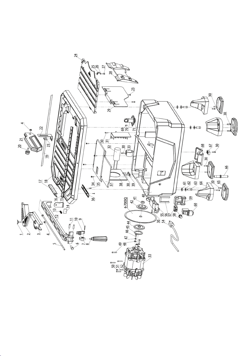
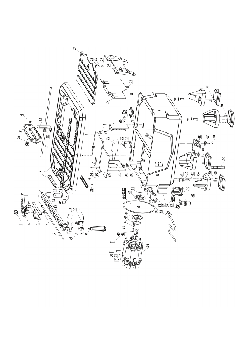
PARTS LIST
See exploded parts (p. 11)
PART # DESCRIPTION Qty
1
Knob of Angle Guide 1
2
Angle Guide 1
3
Base of Angle Guide 1
4
Nut (M6) 2
5
Shank w/ Square Neck 1
6
Shank Sleeve 1
7
Cam 1
8
Spanner of Rip Guide 1
9
Elastic Pin (3x25) 1
10
Holddown Block 1
11
Round Pin 2
12
Rip Guide 1
13
Compression Spring 1
14
Anti-Slip Pad 1
15
Block of Rip Guide 1
16
Measure Guide (A) 1
17
Handle Grip (Upper) 1
18
Master Table 1
19
Measure Guide (B) 1
20
Knob of Blade Guard 1
21
Blade Guard 1
22
Bracket of Blade Guard 1
23 Cross Recessed Pan Head Screw
(M5X10)
4
24
Right Table 1
25
Positioning Spring of Right Table 1
26
Elastic Washer 5 1
27 Cross Recessed Countersunk Head
Screw (M5X10)
1
28
Miter Table Support 1
29
Side Spray Baffle 1
30 Cross Recessed Pan Head Tapping
Screw (ST4.2x15)
13
31
Spray Baffle 1
32
Capacitor 1
33
Capacitor Clamp 1
34 Cross Recessed Countersunk Tapping
Head Screw (ST4.2X15)
4
35 Cross Recessed Countersunk Tapping
Head Screw (ST2.9x15)
2
PART # DESCRIPTION Qty
36
Handle Grip (Lower) 1
37
Cover of Motor 1
38
Wind Guard Board 1
39
Fixing Clip of Cord 1
40
Base 1
41
Nut 1
42
Outer Flange 1
6-7003Q
7" Continuous Rim Diamond Blade 1
44
Inner Flange 1
45
Sealing Pad 1
46
Outer Hexagon Screw (M5 x 15) 2
47
Flat Washer 5 2
48
Water Proof Washer 2
49 Cross Recessed Tapping Screw
(ST4.2x30)
4
50 Cross Recessed Pan Head Screw
(M4x8)
1
51
Elastic Washer 5 1
52
Lock washers internal Teeth 1
53
Motor 1
54
Power Cord 1
55
Power Cord Storage Rack 1
56
Plate of Switch Protection 1
57
Overload Protector 1
58 Water-Proof Cap of Overload
Protector
1
59
Switch Protector 1
60
Switch 1
61
Rubber Washer 4
62
Flat Washer 8 4
63
Inner Hexagonal Bolt M8x18 4
64
Feet 4
65
Bast of Feet 4
66
Anti-Bending Sleeve 1
67
Block of Bench Stop 1
68
Bench Stop 1
69
Fix Cap of Plug 1
70
Plug 1
71
O-Shaped Seal Loop 1
– 11 –
EXPLODED PARTS
– 12 –
CONTENIDO
Instrucciones generales de seguridad ..... 12
Advertencia . . . . . . . . . . . . . . . . . . . . . . . . . . . . 13
Requerimientos eléctricos ...............14
Cables de extensión (alargadores) ......14-15
Proposición 65 de California .............. 15
Descripción ..........................15-16
Montaje..............................16-17
Operación............................18-19
Mantenimiento .......................19-20
Localización de averías ..................20
Lista de piezas..........................21
Despiezado.............................22
INSTRUCCIONES GENERALES
DE SEGURIDAD
LEA ESTE MANUAL
DEL USUARIO EN SU TOTALIDAD Y ASEGÚRESE
DE ENTENDER TODAS LAS PAUTAS DE
SEGURIDAD.
1. MANTENGA LAS PROTECCIONES EN SU LUGAR
y con el orden apropiado para trabajar.
2. REMUEVA LAS LLAVES DE AJUSTE Y LAS
LLAVES INGLESAS. Antes de encender la sierra
eléctrica para cortar losetas asegúrese que
haya quitado las llaves inglesas y las llaves de
tuercas de ajuste.
3. MANTENGA LIMPIA SU ÁREA DE TRABAJO.
Los accidentes suelen ser más comunes en las
áreas que estén desordenadas o por bancas en
el área de trabajo.
4. MANTÉNGASE ALERTA AL UTILIZAR LA
SIERRA. La falta de atención por parte del
operador puede ocasionar accidentes graves.
5. NO LA UTILICE EN AMBIENTES PELIGROSOS.
No utilice herramientas eléctricas en lugares
húmedos o mojados, ni las exponga a la lluvia.
Mantenga bien iluminada el área de trabajo.
6. MANTENGA A LOS NIÑOS ALEJADOS. Todos
las personas en el area deben mantenerse a
una distancia considerable del área de trabajo.
7. ARME SU LUGAR DE TRABAJO A PRUEBA
DE NIÑOS, utilizando candados, interruptores
principales, o quitando las llaves de encendido.
8. UTILICE LA HERRAMIENTA CORRECTA. No
utilize herramientas o accesorios para realizar
un trabajo, en el cual la herramienta no ha sido
diseñada para esa función.
9. UTILICE UN CABLE DE EXTENSIÓN ADECUADO.
Asegúrese de que el cable de extensión está
en buenas condiciones. Cuando utilice un
cable de extensión, asegúrese de que sea lo
suficientemente pesado para transportar la
corriente que requerirá el producto. Un cable de
menor tamaño al requerido causará una caída
en el voltaje de paso y dará como resultado la
pérdida de energía y el recalentamiento. La tabla
(ver la Tabla 1 en la página 26) muestra el tamaño
correcto que debe usarse, teniendo en cuenta la
longitud del cable y la clasificación de amperios
de la placa de datos. Si tuviera dudas, utilice el
siguiente indicador más pesado. Cuanto menor
sea el número del indicador, más pesado será el
cable.
10. NO FUERCE LA HERRAMIENTA. Ha sido diseñada
para funcionar a niveles de máxima seguridad y
rendimiento.
11. NO FUERCE EL MATERIAL QUE DEBE CORTAR.
Siempre deje que la cuchilla corte a la velocidad
para la que fue diseñada.
12. UTILICE UNA VESTIMENTA ADECUADA. No
use ropa suelta, corbatas, anillos, pulseras, u
otros artículos de joyería que pudieran quedar
atrapados en las partes móviles. Se recomienda
usar calzado antideslizante. Use una cubierta
protectora para el cabello si lo tuviera largo.
13. SIEMPRE USE GAFAS DE PROTECCIÓN. También
use máscaras protectoras para la cara y el polvo
en el caso de operaciones de corte comercial.
Las gafas comunes sólo tienen cristales
resistentes a los impactos, pero NO son gafas de
seguridad.
14. NO TRATE DE EXTENDERSE MÁS DE LO
NECESARIO. Mantenga su posición y el equilibrio
en todo momento.
15. MANTENGA LAS HERRAMIENTAS EN BUEN
ESTADO. Mantenga las herramientas limpias y
en buen estado para trabajar para obtener un
máximo rendimiento de seguridad.
SIERRA ELÉCTRICA DE
1HP PARA CORTAR
LOSETAS DE 180MM
MANUAL DE OPERACIÓN
– 13 –
16. DESCONECTE LA SIERRA ELÉCTRICA ANTES
DE HACERLE ALGÚN ARREGLO – al cambiar
accesorios, como cuchillas, puntas, elementos
cortantes, etc.
17. REDUZCA EL RIESGO DE UN ENCENDIDO
INVOLUNTARIO. Asegúrese de que la
herramienta se encuentra en posición de
APAGADO antes de enchufarla.
18. UTILICE LOS ACCESORIOS RECOMENDADOS.
Consulte el manual del usuario para los
accesorios recomendados. El uso de accesorios
inadecuados puede ocasionar accidentes.
19. NO REALICE CORTES EN SECO CON DISCOS
DE DIAMANTE DISEÑADOS PARA REALIZAR
CORTES CON AGUA.
20. ASEGÚRESE DE USAR LA CUCHILLA CORRECTA
para el trabajo que está realizando.
21. NUNCA SE APOYE SOBRE LA HERRAMIENTA.
Puede tener un accidente grave si la
herramienta se mueve o si se toma contacto
involuntario con la parte cortante.
22. REVISE LAS PARTES DAÑADAS. Antes de
volver a utilizar la herramienta debe revisar
cuidadosamente la(s) parte(s) dañada(s),
(por ejemplo la protección), para saber si
funcionará en forma adecuada y cumplirá con
su función. Revise la alineación de las partes
móviles, la unión de las mismas, si se rompieron,
superpusieron y cualquier otra condición que
pueda afectar el funcionamiento de la sierra.
Las protecciones u otras partes que estén
dañadas deben repararse o reemplazarse
adecuadamente.
23. Asegúrese que el DISCO DE CORTE ESTÉ
PASANDO A TRAVÉS DE LA RESERVA DE AGUA
PARA OBTENER UN CORTE EN HÚMEDO.
24. REVISE CUIDADOSAMENTE LOS DISCOS DE
DIAMANTE en caso de grietas, rajaduras,
que la matriz de diamante falte o que esté
desalineado. Reemplace las cuchillas dañadas
inmediatamente. NO USE DISCOS DAÑADOS.
Pueden causar accidentes graves.
25. DIRECCIÓN DE LA ALIMENTACIÓN. Solamente
coloque el trabajo en la cuchilla en dirección
contraria a la rotación de la cuchilla.
26. NO ALTERE EL ENCHUFE O USE UN
TOMACORRIENTE DE 2 PUNTAS. Esta sierra
está equipada con un enchufe eléctrico de
3 puntas.
27. NUNCA DEJE LA SIERRA ELÉCTRICA
ENCENDIDA SIN PRESTARLE ATENCIÓN.
Apáguela. No deje la herramienta hasta que se
haya detenido completamente.
28. COLOCACIÓN DE LA SIERRA ELÉCTRICA PARA
LOSETAS (ver el FIGURA 1)
FIGURA 1
• Para evitar que el tomacorriente o enchufe
del accesorio se humedezcan, coloque la
sierra eléctrica para losetas hacia un lado del
tomacorriente que se encuentra en la pared, para
que el agua no caiga sobre éste o el enchufe. El
usuario debería realizar una "vuelta de goteo" en
el cable que conecta la sierra al tomacorriente. La
"vuelta de goteo" es la parte del cable por debajo
del nivel del tomacorriente, o el conector si se
utiliza un cable de extensión, que evita que el
agua se deslice por el cable y entre en contacto
con el tomacorriente.
• Si el enchufe o el tomacorriente se
humedecieren, NO DESENCHUFE el cable.
Desconecte el fusible o el interruptor automático
que suministra electricidad a la herramienta.
Luego desenchúfela y revise si hay agua en el
tomacorriente.
ADVERTENCIA
EL USO INADECUADO PUEDE OCASIONAR
GRAVES ACCIDENTES.
• Mantenga los dedos y la ropa que esté suelta
alejados del disco de diamante giratorio.
• Sea sumamente cuidadoso al cortar losetas.
Asegúrese de que las manos y los dedos estén
alejados de la ranura de la cuchilla en la mesa.
Puede rasparse, cortarse o apretarse los dedos
gravemente.
• Si no se siguen las instrucciones de funcionamiento
puede producirse una descarga eléctrica.
PARA SU SEGURIDAD LEA EL MANUAL
DE INSTRUCCIONES ANTES DE PONER EN
FUNCIONAMIENTO LA SIERRA.
• Use protección para los ojos.
• Use una máscara protectora siempre que
sea necesario.
– 14 –
• Desconecte la sierra antes de hacerle alguna
reparación, cuando le cambie los discos de
diamante, y antes de limpiarla.
• Use la herramienta sólo con discos de diamantes
que tengan los de bordes libres de aberturas y
ranuras.
• Reemplace el disco de diamante que esté dañado
antes de poner la sierra en funcionamiento.
• No llene la bandeja de agua por encima del drenaje.
REQUERIMIENTOS
ELÉCTRICOS
1. ESTA SIERRA ELÉCTRICA PARA LOSETAS
DEBE TENER UNA CONEXIÓN POLO A TIERRA
mientras está en uso para evitar que el
operador sufra una descarga eléctrica.
2. EN EL CASO DE MAL FUNCIONAMIENTO
O FALLA ELÉCTRICA, la conexión polo a
tierra proporciona un suministro de menor
resistencia de corriente eléctrica para reducir
el riesgo de una descarga eléctrica. Esta
herramienta está equipada con un cable
eléctrico con un conductor con conexión polo
a tierra y un enchufe con conexión polo a
tierra. Conecte el enchufe eléctrico de 3 puntas
a una toma de 3 polos debidamente instalado y
con una conexión polo a tierra conforme a los
códigos y regulaciones locales.
3. NO MODIFIQUE EL ENCHUFE SUMINISTRADO
si éste no se adapta la toma. Instale la toma
adecuado con la ayuda de un electricista
profesional.
4. LA CONEXIÓN INADECUADA DEL CONDUCTOR
CON LA CONEXIÓN POLO A TIERRA DEL
EQUIPO PUEDE OCASIONAR UNA DESCARGA
ELÉCTRICA. El conductor con aislamiento que
posee una superficie externa verde (con o sin
franjas amarillas) es el conductor de conexión
polo a tierra del equipo. Si fuera necesario
reparar o reemplazar el cable eléctrico o
enchufe no conecte el conductor de conexión
polo a tierra del equipo a una terminal activa.
5. CONSULTE A UN ELECTRICISTA
PROFESIONAL si no entendiera completamente
las instrucciones para la conexión polo a tierra;
o si tuviera dudas acerca de si la herramienta
está conectada correctamente polo a tierra.
6. UTILICE SOLAMENTE CABLES DE EXTENSIÓN
DE 3 CONDUCTORES que poseen enchufes
de conexión polo a tierra de 3 puntas y
tomacorrientes de 3 polos que aceptan el
enchufe de la sierra eléctrica para cortar
losetas.
7. REPARE O REEMPLACE INMEDIATAMENTE EL
CABLE GASTADO O DAÑADO.
8. SI EL ENCHUFE O TOMACORRIENTE SE
HUMEDECIERAN, NO DESENCHUFE EL
CABLE. Desconecte el fusible o el interruptor
automático que suministra electricidad a la
herramienta. Luego desenchúfela y revise si hay
agua en el tomacorriente.
9. CON ESTE PRODUCTO SÓLO PUEDEN USARSE
CABLES DE EXTENSIÓN CALIFICADOS POR UL.
10. EL USO INADECUADO DE CABLES DE
EXTENSIÓN PUEDE PRODUCIR UN
FUNCIONAMIENTO DEFICIENTE DE LA
HERRAMIENTA, que puede dar como resultado
el recalentamiento. Asegúrese de que el cable
de extensión tenga la potencia adecuada para
suministrar una corriente eléctrica suficiente
al motor. Para calibrar su herramienta en forma
adecuada consulte el TABLA 1 (página 26).
11. NO TOQUE CON LOS DEDOS las terminales del
enchufe al conectar o desconectar el enchufe
del toma.
12. ESTA SIERRA ELÉCTRICA PARA CORTAR LOSETAS
DEBE SER INSTALADA APROPIADAMENTE POLO
A TIERRA. Si no lo estuviera aumentaría
enormemente el riesgo de descargas eléctricas y
accidentes, particularmente si se utilizara en
lugares húmedos o cercanos a cañerías.
NOTA: La sierra electrica professional esta
diseñada para ser conectada en un toma corriente
empotrado y conectado a tierra como el que se
encuentra en la FIGURA 2(B). Ademas esta sierra
tiene un toma corriente de tierra como el de la
FIGURA 2(A).
Tornillo
de
metal
(B) Toma corriente
empotrado y
conectado a tierra
(A) Pernos
de tierra
FIGURA 2
CABLES DE EXTENSIÓN
(ALARGADORES)
1. Utilice solamente los cables de extensión
destinados para uso en áreas exteriores. Puede
identificarlos con la leyenda “Pueden usarse con
dispositivos para exteriores: guardar en el interior
– 15 –
cuando no se use.” Utilice solamente los cables
de extensión que tengan una clasificación
eléctrica no menor a la clasificación del
producto. No utilice el cable de extensión si
está dañado, reemplácelo. Examine el cable de
extensión antes de usarlo y suspenda el uso si
está dañado. No maltrate el cable de extensión
y no lo desconecte de un tirón. Mantenga el
cable alejado del calor y los bordes filosos.
Siempre desconecte el cable de extensión del
tomacorriente antes de desconectar el producto
del cable de extensión.
PARA REDUCIR
EL RIESGO DE ELECTROCUCIÓN, MANTENGA
TODAS LAS CONEXIONES SECAS Y LEJOS
DEL SUELO. NO TOQUE EL ENCHUFE CON LAS
MANOS MOJADAS.
2. El/los circuito/s o toma/s que se usarán con la
sierra para losetas/azulejos deben contener un
Interruptor de Circuito Polo a Tierra (GFCI) como
protección. Se pueden obtener tomacorrientes
con protección GFCI incorporada para usarse
de acuerdo con esta medida de seguridad.
3. UTILICE UN CABLE DE EXTENSIÓN
ADECUADO. Asegúrese de que el cable
de extensión esté en buenas condiciones.
Cuando utilice un cable de extensión,
asegúrese de que sea lo suficientemente
pesado para transportar la corriente que
requiera el producto. Un cable de tamaño
reducido causará una caída en el voltaje
de paso, y dará como resultado la pérdida
de energía y el recalentamiento. La TABLA
muestra el tamaño correcto que debe usarse,
teniendo en cuenta la longitud del cable y la
clasificación de amperios en la placa de datos.
Si tuviera dudas, utilice el siguiente indicador
más pesado. Cuanto menor sea el número del
indicador, más pesado será el cable.
NOTA: Cuando utilice un cable de extensión,
asegúrese de que todos los cables no tengan
un calibre menor al # 12, con una potencia de
20-amperios como mínimo, y estén equipados
con enchufes de 3 puntas. El uso de cualquier
cable menor puede ocasionar el recalentamiento
o que se queme el motor. Se recomienda que
un electricista revise el voltaje en el motor de la
sierra para asegurarse de que tiene el voltaje
adecuado para que la sierra funcione de manera
eficaz y segura.
PROPOSICIÓN 65
DE CALIFORNIA
ALGUNOS POLVOS
CREADOS POR LIJADORAS MECÁNICAS,
ASERRADEROS, TRITURADORES, PERFORADORAS
Y OTRAS ACTIVIDADES DE CONSTRUCCIÓN
CONTIENEN SUSTANCIAS QUÍMICAS QUE SE
SABE (EN EL ESTADO DE CALIFORNIA) CAUSAN
CÁNCER, DEFECTOS DE NACIMIENTO U OTROS
DAÑOS AL SISTEMA REPRODUCTIVO.
Algunos ejemplos de estas sustancias químicas
son:
• Plomo derivado de pinturas a base de plomo.
• Sílice cristalino de los ladrillos, cementos y otros
tipos de productos de albañería.
• Arsénico y cromo de madera tratada con
sustancias químicas.
El riesgo de exposición a éstas situaciones varía,
dependiendo de cuantas veces se hace este
tipo de trabajo. Para reducir el contacto con
estas sustancias químicas: trabaje en lugares
bien ventilados y con equipos aprobados para
la protección, como mascarillas para el polvo
que son diseñadas especificamente para filtrar
partículas microscopias.
DESCRIPCIÓN
Antes de intentar utilizar cualquier herramienta
asegúrese que esté familiarizado con todas
las características de operación y con las
instrucciones de seguridad.
Régimen de amperios
Voltios Longitud total del cable en pies
120 V 7.62 m 15,24 m 30,48 m 45.72 m
240 V 15,24 m 30,48 m 60,96 m 91,44 m
Más de No más de AWG
0 6 18 16 16 14
6 10 18 16 14 12
10 12 16 16 14 12
12 16 14 12 No recomendado
TABLA 1
– 16 –
CONOZCA SU SIERRA
Su sierra para cortar losetas tiene muchas
características integradas corta loseta de
cerámica, loseta de porcelana, mármol, pizarra
y piedra. El disco de corte de 180 mm es de larga
duración, corta losetas que tengan un grosor
hasta de 29 mm. Las guias de corte lineal y en
ángulo permiten hacer cortes lineales a 90° ó
cortes en ángulo de 22,5° y a 45° en ambos lados
tanto el derecho como el izquierdo. La mesa de
corte del lado derecho está articulada para poder
ajustarla y hacer cortes a inglete a 15°, 30° o
45°. La mesa de la derecha tiene una reserva de
agua para refrescar el disco de corte. La reserva
de agua tiene una abertura para cuando haya
desbordamiento, para así mantener el nivel de
agua apropiado. La manija integrada permite
transportarla fácilmente.
FIGURA 3
ESPECIFICACIONES DEL PRODUCTO
Entrada: 6.5 Amperios
Velocidad sin carga: 3600 RPM
Salida: 1 máximo de caballos de fuerza
Diámetro del disco de corte: 180 mm
Eje: 16 mm
Rango: 120 Voltios, 60 Hercios
Profundidad del Corte: 29 mm
MONTAJE
SIGA TODAS LAS
INSTRUCCIONES ACERCA DEL MONTAJE E
INSTALACIÓN QUE ESTÁN EN ÉSTE MANUAL,
ANTES DE CONECTAR LA SIERRA PARA
CORTAR LOSETAS EN LA TOMA ELÉCTRICA
Y ENCENDERLA.
DESEMPAQUE
1. Remueva todos los materiales de empaque que
están alrededor de su sierra.
2. Con cuidado levante la sierra y sáquela del
cartón colocándola en una superficie que esté
al nivel para trabajar.
3. No deseche los materiales de empaque hasta
que usted no haya inspeccionado bien la sierra
si llegará a tener alguna parte suelta o dañada.
Los siguientes artículos están incluidos en la
caja con su sierra para cortar losetas:
• Sierra eléctrica de corte en húmedo
• Disco de diamante de 180 mm (7 in.)
• Protección de seguridad del disco
• Guía para corte recto
• Guía para corte en ángulo
• Soporte trasero
• Manual del usuario
4. Inspeccione cuidadosamente la sierra para
asegurarse que durante el transporte no
se haya roto a dañado. Si alguna parte está
dañada o le falta alguna parte llamar a servicio
al cliente al numero 866-435-8665
SI ALGUNA
PARTE ESTÁ DAÑADA O LE HACE FALTA, NO
INTENTE UTILIZAR ESTA SIERRA. SI UTILIZA
ESTA SIERRA CON ALGUNA PARTE DAÑADA O
SIN UNA PARTE QUE LE HAGA FALTA, PODRÍA
RESULTAR EN UNA SERIA LESIÓN PERSONAL.
INSTALACIÓN DEL DISCO DE CORTE
1. Remueva la mesa de corte de la derecha.
2. Remueva el deflector (ver la FIGURA 4).
FIGURA 4
3. Remueva la tuerca del eje del disco de corte
y la pestaña exterior.
4. Cuidadosamente coloque el disco de corte
sobre el eje y empújelo hacia la pestaña
interior.
5. Asegúrese que la cara del disco de corte
que tiene ilustrada la flecha direccional este
mirando hacia usted.
6. Coloque la pestaña exterior y la tuerca del eje
en el disco de corte.
– 17 –
7. Apriete firmemente la tuerca del eje del disco de
corte con la llave que ha sido incluida pero no la
apriete demasiado (ver la FIGURA 5).
FIGURA 5
8. Vuelva a colocar el reflector y la mesa de corte
de la derecha.
CON ESTA SIERRA,
SOLAMENTE UTILICE DISCOS DE CORTE CON
BANDA CONTINUA. NO UTILICE DISCOS DE
CORTE CON BANDA SEGMENTADA, TURBO,
PARA CORTAR MADERA, CON ABERTURAS O
CON NINGÚN OTRO ARTÍCULO PARA CORTAR
CON ESTA SIERRA. SI UTILIZA ÉSTE TIPO DE
DISCOS DE CORTE PODRÍA CAUSAR LESIONES
PERSONALES MUY SERIAS Y DAÑAR LA SIERRA.
INSTALACIÓN DEL PROTECTOR DEL
DISCO DE CORTE
1. Coloque el soporte del protector del disco de
corte dentro de la ranura que se encuentra en la
parte superior en el costado trasero de la mesa.
(Figura 6)
2. Asegúrese que el soporte quede alineado con el
disco de corte.
FIGURA 6
3. Deslice la parte trasera del protector del disco
de corte hacia abajo donde está el soporte del
disco de corte (ver la FIGURA 7).
4. Vuelva a colocar la perilla en el protector del
disco de corte, mientras con mucho cuidado
sostenga el perno a la derecha en su lugar,
despues ajústela (ver la FIGURA 7).
FIGURA 7
5. Es sugerido que el frente del protector del disco
quede mirando un poco hacia abajo para minimizar
que salpique al frente mientras esté cortando.
INSTALACIÓN DE LA GUÍA PARA
CORTES RECTOS
1. Deslice la parte trasera de la guía de corte en
el borde trasero de la mesa (Ver la FIGURA 8)
2. Coloque la parte frontal de la guía de corte
hacia abajo en el borde posterior de la sierra.
3. Ajuste la posición en el tamaño de corte
deseado, y gire hacia abajo la palanca para
bloquear a la guía de corte en su lugar.
(Ver la FIGURA 9)
4. El perno redondo sobre la palanca, también
se utiliza para ajustar la guía de corte recto.
CONTRA
LOS PELLIZCOS. MANTENGA LAS MANOS
ALEJADAS DE LA PALANCA BASCULANTE
CUANDO SE ENCUENTRE BLOQUEANDO Y
DESBLOQUEANDO LA GUÍA DE CORTE RECTO.
FIGURA 8
FIGURA 9
– 18 –
INSTALACIÓN DE LA GUÍA
PARA ÁNGULOS
(ver la FIGURA 10)
1. La guía para ángulos está diseñada para ser
colocada en la parte de arriba de la guía para
cortes rectos. Simplemente coloque la dentada
que está en la guía para ángulos en la parte de
arriba de la guía para cortes rectos.
NOTA: La guía para ángulos puede colocarse en
cualquiera de los dos lados tanto en el izquierdo
como el derecho.
FIGURA 10
OPERACIÓN
IMPORTANTE: SIEMPRE apague la sierra y
remueva el enchufe de la toma eléctrica ÁNTES
de añadir o remover los accesorios y hacerle
ajuste.
SI NO
DESCONECTA LA SIERRA PODRÍA INICIAR
ACCIDENTALMENTE LA SIERRA Y PODRÍA
CAUSAR POSIBLES LESIONES GRAVES
PERSONALES.
ANTES DE INICIAR LA SIERRA
1. Asegúrese que la sierra esté desconectada.
2. Levante la mesa de corte de la derecha y llene
la reserve de agua hasta el tope de la abertura
de desbordamiento. (vea FIGURA 11). No lo
llene más arriba de éste nivel.
NOTA: SIEMPRE mantenga suficiente agua en la
reserva de agua mientras esté utilizando la sierra.
NO permita que la sierra funcione sin agua.
3. Cierre la mesa de corte de la derecha.
IMPORTANTE: SIEMPRE drene muy bien la
reserva de agua y límpiela completamente
después de cada uso.
FIGURA 11
PARA DARLE INICIO A LA SIERRA
1. Remueva el cordón del compartimiento al
costado y conecte el cable en una toma
protegida por un Interruptor de Protección del
Circuito de Fallas de Conexión a Tierra (ver la
FIGURA 12).
FIGURA 12
2. Haga una “cueva de goteo’’ en el cable (ver la
FIGURA 12).
FIGURA 13
HACIENDO CORTES
En el borde de la mesa podrá ver fácilmente las
dimensión (en pulgadas y en centímetros) para
hacer corte precisos.
IMPORTANTE: SIEMPRE permita que el disco de
corte haga el corte a su propia velocidad. NO
fuerce el material a cortar. SIEMPRE verifique
– 19 –
que el disco de corte no tenga grietas o daños
ANTES de cada uso.
HACIENDO CORTES LINEALES A 90°
1. Instale la guía para cortes lineales colocándola
en la posición deseada, de acuerdo al ancho
del corte que está realizando.
2. Coloque el material a cortar contra la guía para
cortar.
3. Cuidadosamente empuje el material hacia el
disco de corte (
ver la FIGURA 14)
.
4. Si es necesario, la guía para cortes lineales
puede removerla cuando esté cortando losetas
de formato grande.
FIGURA 14
HACIENDO CORTES EN ÁNGULO
DESDE 22.5° Y 45°
1. Instale la guía para ángulos sobre la guía para
cortes rectos.
2. Afloje el perno. Coloque la guía en el ángulo
deseado (22.5° ó 45°) y coloque la loseta en la
guía.
3. Cuidadosamente empuje la guía para ángulos y el
material hacia el disco de corte (ver la FIGURA 15).
FIGURA 15
HACIENDO CORTES A INGLETE
DE 15°, 30° & 45°
(ver la FIGURA 16)
1. La mesa de corte a la derecha puede colocarla
en ángulo a 15° or 30° or 45°.
2. Los dos refuerzos que están debajo de la mesa
podrá desdoblarlos para darle soporte a la
mesa en el ángulo deseado.
3. Coloque el material a cortar sobre el lado
izquierdo de la mesa.
4. Cuidadosamente empuje el material hacia el
disco de corte.
FIGURA 16
SEGURO PARA MESA
(ver la FIGURA 17)
1. El conveniente seguro para mesa mantiene la
sierra en su lugar durante los cortes.
FIGURA 17
MANTENIMIENTO
PARA EVITAR
ACCIDENTES, SIEMPRE DESCONECTE LA
SIERRA DE LA FUENTE DE ELECTRICIDAD
ANTES DE LIMPIARLA O HACERLE ALGÚN
MANTENIMIENTO.
Por favor no intente hacerle algún servicio a esta
sierra usted solo.
Evite utilizar solventes cuando esté limpiando las
parte plásticas. La mayoría de las partes plásticas
son susceptibles a dañarse a causa de varios
tipos de solventes comerciales y también podrían
dañarse por su uso. Utilice un trapo limpio para
remover mugre, polvo etc.

– 20 –
NUNCA PERMITA
QUE LÍQUIDOS PARA FRENOS, GASOLINA,
PRODUCTOS A BASE DE PETRÓLEO, ACEITES
PENETRANTES ETC., ENTREN EN CONTACTO
CON LAS PARTES PLÁSTICAS. ESTOS
CONTIENEN QUÍMICOS QUE PUEDEN DAÑAR,
DEBILITAR O DESTRUIR PLÁSTICO.
1. SIEMPRE limpie la sierra para losetas después
de cada uso y guarde la sierra para losetas en
un área seca.
2. SIEMPRE limpie todas las superficies
exteriores y mantenga la mesa de corte limpia
y libre de desechos.
3. SIEMPRE revise el disco de corte a ver si tiene
grietas o demuestra algún signo de estar
dañado ANTES de cada uso.
4. SIEMPRE guarde el cable en el
compartimiento que está en la parte de abajo
de la sierra después de cada uso.
DISCOS DE DIAMANTE
• Utilice en esta sierra solamente un disco de
diamante de banda continua de 100 mm con un
apertura de eje de 16 mm. De no ser así podría
resultar en causarse daños físicos o dañar la sierra.
QUÉ HACER Y QUÉ NO HACER CON
EL DISCO DE DIAMANTE
1. Revisar los discos de diamante diariamente
en caso de roturas o desgaste desparejo.
¡No utilizar discos de diamante rotos,
astilladas o dobladas!
2. Seguir siempre las recomendaciones del
fabricante para utilizar la cuchilla adecuada
para el material que se desea cortar.
3. Revisar el eje en caso de desgaste desparejo
antes de colocar el disco de diamante.
4. Usar siempre discos de diamante con
el tamaño de eje adecuado en un eje
compatible.
5. Asegurarse de que se colocó el disco de
diamante con la flecha de rotación en
la dirección correcta y que está sujeto
firmemente con la llave de tuerca.
6. Usar siempre el equipo de seguridad
adecuado al operar la sierra. Usar gafas
protectoras y máscara para el polvo en todo
momento.
7. Revisar periódicamente la cuchilla en caso
de roturas o fatiga del material.
8. Asegúrese que el disco de corte esté pasando
a través de la reserva de agua para realizar el
corte en húmedo.
9. No opere la sierra sin colocar todos los
elementos de seguridad en posición.
10. No use la sierra con discos de diamante
más grandes o más pequeños que los
recomendados.
11. No utilice discos de corte que no sean sutiles
para cortar en húmedo
12. No exceda del máximo de RPM recomendadas
por el fabricante de la cuchilla.
13. No fuerce el material dentro de la cuchilla.
Dejar que la cuchilla corte a su propia
velocidad.
14. No corte materiales distintos a los
recomendados por el fabricante de la cuchilla.
LOCALIZACIÓN DE AVERÍAS
SOBRECALENTAMIENTO
DE LA SIERRA:
1. Apague la sierra eléctrica tipo puente y déjela
en reposo hasta que el motor esté frío al tacto.
2. Verifique y limpie las ranuras de ventilación,
quite cualquier obstrucción y suciedad.
LA SIERRA NO ARRANCA:
1. Verifique que el cable de alimentación esté
enchufado correctamente.
2. Revise la fuente de energía de la toma eléctrica
y el corta circuito.
3. Verifique si el cable de extensión eléctrico está
en condiciones de funcionamiento.
SERVICIO AL CLIENTE:
1-866-435-8665

– 21 –
LISTA DE PIEZAS
Ver el diagrama de las partes en la página 22.
PIEZA DESCRIPCIÓN
CANT.
1
Perilla de guía de ángulo 1
2
Guía para corte en ángulo 1
3
Base de la guía para corte en ángulo 1
4
Tuerca (M6) 2
5
Vástago con cuello cuadrado 1
6
Manga de vástago 1
7
Leva 1
8
Llave de guía de corte 1
9
Pasador elastic (3x25) 1
10
Bloque de retención 1
11
Perno redondo 2
12
Guide pour Coupe Longitudinale 1
13
Resorte de compression 1
14
Almohadilla antideslizante 1
15
Bloque de guía de corte 1
16
Guía de medir (A) 1
17
Agarradero de mango (de arriba) 1
18
Mesa principal 1
19
Guía de medir (B) 1
20
Perilla del protector del disco de corte 1
21
Protector del disco de corte 1
22
Soporte del protector de la hoja 1
23 Tornillo de cabeza plana con un receso en
cruz (M5X10)
4
24
Mesa derecha 1
25 Resorte de posicionamiento de la mesa
derecha
1
26
Arandela elástica (4) 1
27 Tornillo de cabeza avellanada con un receso
en cruz (M5X10)
1
28
Soporte de la mesa de inglete 1
29
Deflector rociador lateral 1
30 Tornillo autorroscante de cabeza plana con
un receso en cruz (ST4.2x15)
13
31
Deflector de espray 1
32
Condensador 1
33
Pinza condensador 1
34 Tornillo autorroscante de cabeza avellanada
con un receso en cruz (ST4.2X15)
4
35
Tornillo autorroscante de cabeza avellanada
con un receso en cruz (ST2.9x15)
2
PIEZA DESCRIPCIÓN
CANT.
36
Agarradero de mango (de abajo) 1
37
Cubierta del motor 1
38
Tablero de protección contra el viento 1
39
Abrazadera para sostener el cable 1
40
Base 1
41
Tuerca 1
42
Pestaña exterior 1
6-7003Q
Disco de corte de banda continua de 180 mm 1
44
Pestaña interior 1
45
Almohadilla de sellado 1
46
Tornillo hexagonal exterior (M5 x 15) 2
47
Arandela plana 5 2
48
Arandela impermeable 2
49 Tornillo autorroscante con un receso en
cruz (ST4.2x30)
4
50 Tornillo autorroscante con un receso en
cruz(M4x8)
1
51
Arandela elástica 5 1
52
Dentada interna de la arandela de bloqueo 1
53
Motor 1
54
Cable de alimentación 1
55 Estante de almacenaje del cable de alimen-
tación
1
56
Placa de interruptor de protección 1
57
Protector de sobrecarga 1
58 Casquillo impermeable de protector de
sobrecarga
1
59
Protector de interruptor 1
60
Interruptor 1
61
Arandela de goma 4
62
Arandela plana 8 4
63
Perno hexagonal interior M8x18 4
64
Patas 4
65
Patas de la base 4
66
Manga anti-flexión 1
67
Bloqueo del seguro para mesa 1
68
Seguro para mesa 1
69
Casquillo fijo de enchufe 1
70
Enchufe 1
71
Sello en forma de – O 1
– 22 –
DESPIEZADO

© 2016 Distributed by Menard, Inc.
Eau Claire, WI 54703 MADE IN CHINA
Visit MENARDS.COM
®
S216-10043