Loading ...
Loading ...
Loading ...
14
COMBUSTION AIR SUPPLY
If outdoor combustion air is supplied the heater must be attached to the structure.
For a mobile home installation the stove must be connected to an outside source of combustion air. A 2” inside diameter
metallic pipe, either fl exible or rigid, may be attached to the inlet at the stove’s rear.
A rodent guard (minimum ¼” wire
mesh)/wind hood must be used at the terminus.
All connections must be secured and airtight by either using the appro-
priately sized hose clamp and/or UL-181-AP foil tape.
For mobile home installations only: 2” inside diameter pipe may be used for the fi rst 5 feet of combustion air supply
run. From 5 to 10 feet use 2 ¾” inside diameter pipe. No combustion air supply may exceed 10 feet.
SOURCES OF OUTSIDE COMBUSTION AIR
In fi replaces
• Chimney top.
• Ash clean out door.
WHEN OUTSIDE AIR IS NOT USED
If outside air is not used, it is important that combustion air is easily available to the air inlet. A closeable outs
ide air reg-
ister can be used in tightly insulated homes.
In insert installations, fl ashing vents should not be restricted. The fl ashing
should not necessarily seal the fi replace face.
DO NOT CONNECT THIS UNIT TO A CHIMNEY FLUE SERVING ANOTHER APPLIANCE.
INSERT INSTALLATIONS
Insert installations must be vented with 3” or 4” pipe. Pipe may be single wall stainless steel fl exible pipe. Vent may termi-
nate within chimney beyond a blanking plate or extend to the chimney top. See “COMBUSTION AIR SUPPLY” for outside
air access information.
The fi replace and chimney should be cleaned thoroughly before starting the installation. We suggest painting the
interior of particularly old and dirty fi replaces to seal any odors.
ASSEMBLING THE FLASHING SET
Follow the instructions packaged with this stoves Flashing.
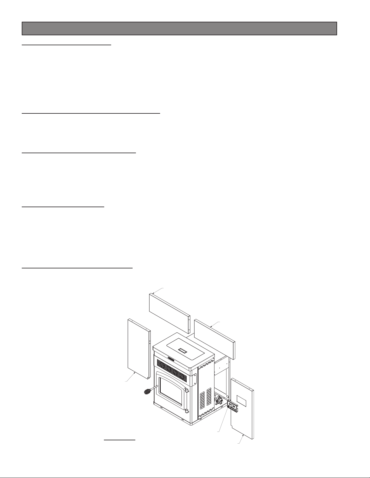
INSTALLATION
LEFT SIDE TOP
SURROUND PANEL
RIGHT SIDE
TOP SURROUND PANEL
LEFT SIDE
SURROUND PANEL
RIGHT SIDE
SURROUND PANEL
CIRCUIT BOARD
FIGURE 12
INSERT INSTALLATION
Loading ...
Loading ...
Loading ...