Questions, problems, missing parts?
Before returning to your retailer, call our customer service at 1-800-887-6326
Monday – Friday 9:00 a.m. – 5:00 p.m. CST
SKU Number: 356-2471
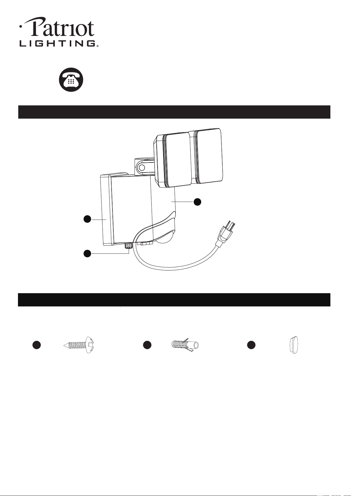
SENSOR LIGHT
Model Number: E8237B
Page 1 of 5
200720
HARDWARE CONTENTS Note: Hardware not shown actual size.
PACKAGE CONTENTS
A
B
C
Anchor
X2
Drywall Screw
X2
AA
Decorative Cover
X2
CCBB
Before beginning assembly, installation or operation of product, make sure all parts are present. Compare parts with
package contents list and diagram on previous page. If any part is missing or damaged, do not attempt to assemble,
install or operate the product. Contact customer service for replacement parts.
Tools Required for Assembly (not included): Screwdriver, Phillips Screwdriver, Pliers, Electrical Tape, Wire Cutters,
Safety Glasses, Ladder, Wire Stripper.
Page 2 of 5
SAFETY INFORMATION
PREPARATION
Important to know
200720
ASSEMBLY INSTRUCTIONS
1. This fixture requires a 120 VAC, 60 Hz power source.
2. For general safety and to avoid any possible damage to the sensor, be sure the power is switched "off" before
adjustment.
3. Motion sensor: turns light ON automatically when motion is detected and turns light OFF automatically when motion
stops.
4. Photocell keeps the light OFF during daylight hours
5. When in manual override mode, use wall switch to keep the light ON during the night.
• All electrical connections must be in agreement with local codes, ordinances or the national electric code (NEC).
Contact your municipal building department to learn about your local codes, permits and/or inspections.
• Risk of fire – most dwellings built before 1985 have supply wire rated for 140°F/60ºC. Consult a qualified electrician
to ensure correct branch circuit conductor.
• RISK OF ELECTRIC SHOCK, do not use with extension cord near water or where water may accumulate. Keep
lamp at least 16 feet from pools and spas. Keep plugs and receptacles dry.
• For use only on GFCI protected circuits.
• Units intended for damp or wet location: “DO NOT SUBMERSE” & “NE PAS IMMERGER” .
Please read and understand this entire manual before attempting to assemble, operate or install the product.
WARNING
•
Turn off electricity at main fuse box (or circuit breaker box) before beginning installation by removing fuse (or switching
off circuit breaker).
• Be careful not to damage or cut the wire insulation (covering) during fixture installation. Do not permit wires to contact
any surface having a sharp edge. To do so may damage or cut the wire insulation, which could cause serious injury
or death from electric shock.
CAUTION
Maximum Wattage: 13W
Work Temperature: - 4°F~113°F
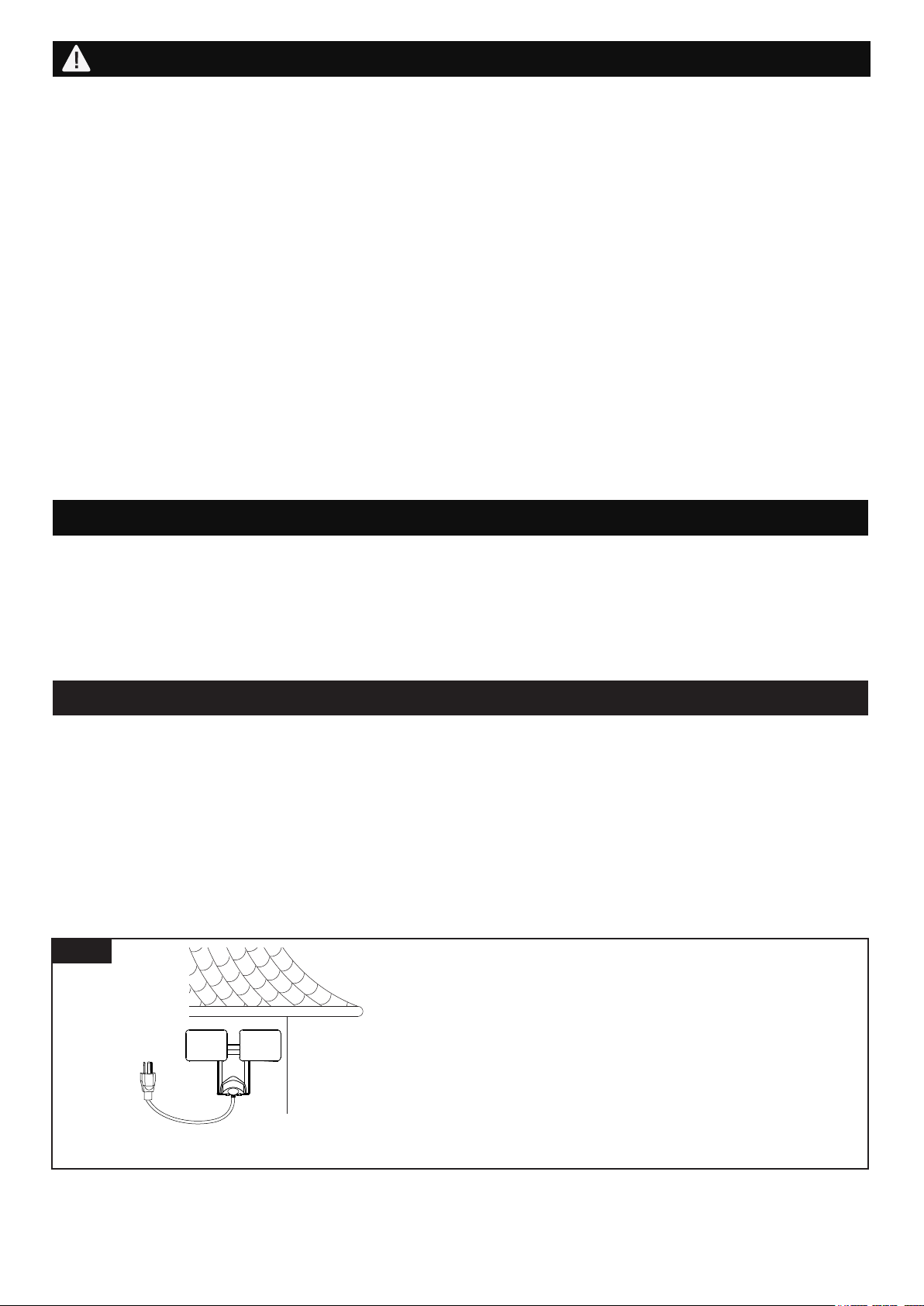
Fig.1
Note: Fixture can be wall mounted only.
Wall Mounted
Read notes section on page 4-5 for additional
information about mounting location of fixture.
Light fixture and sensor should be mounted as
shown when installed.
Page 3 of 5
ASSEMBLY INSTRUCTIONS (continued)
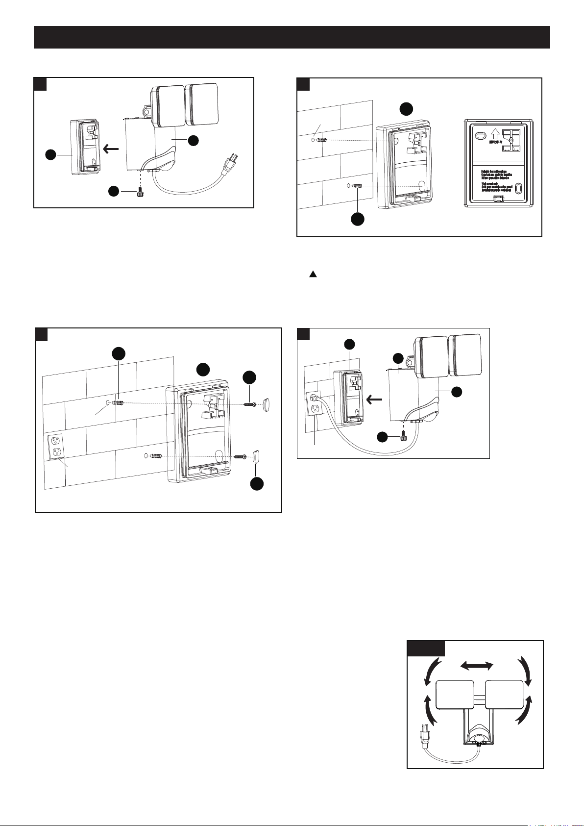
Installation Steps
1.The mounting bracket (B) is pre-assembled on the
light fixture (A). Unscrew set screw (C) to remove
the mounting bracket (B).
4. Place the light fixture (A) to the mounting bracket (B)
and secure it with set screw (C), and then attach the
power plug to the outlet socket.
200720
1
A
B
C
2. Hold the mounting bracket (B) to the wall and mark the
set holes on the wall surface for drilling.
When mounting to a wall, the “THIS END UP” arrow
must point up.
3. Drill two holes. Insert the anchors (BB) into the holes,
attach the mounting bracket (B) to the wall and thread
the drywall screws (AA) through the mounting bracket (B)
into the set hole, tighten the dry wall screws (AA) securely,
and press the decorative cover (CC).
Adjusting the Light Head:
1. Adjust the light heads up or down,left or right for desired area. (See Fig. 2)
2. Keep the light heads 30˚ below horizontal to avoid water damage and electrical
shock.
Sensitivity of Motion Sensor:
● You can adjust the sensitivity of the motion sensor by using the “MOTION SENSITIVITY” selector located at
the bottom of light body (See Fig. 3).
Note: Range set too high may increase false triggering.
● Adjust motion sensor sensitivity to achieve desired performance.
● Approximate range for each setting from 20ft to 40ft.
Fig. 2
Set Hole
2
BB
B
Outlet Socket
Set Hole
3
BB
CC
AA
B
A
Outlet Socket
4
B
D
C
Page 4 of 5
200720
Notes:
1. The sensitivity of the motion sensor will increase as the
environmental temperature gets cooler. For best
performance, gently clean the lens with a soft cloth every
1 or 2 months to ensure maximum sensitivity.
2. For best performance, install fixture at least 8 feet above
the ground. At such a height, the fixture will provide a
detection distance of up to 40 feet at 77 degrees
Fahrenheit. (See Fig.5)
3. The sensor detects movement across a detection range
of 180 degrees. (See Fig.6)
20`
8`
12`
40`
Be sure the light is mounted straight on the wall;
otherwise, the detection distance may be limited.
Fig. 5 Fig. 6
180˚
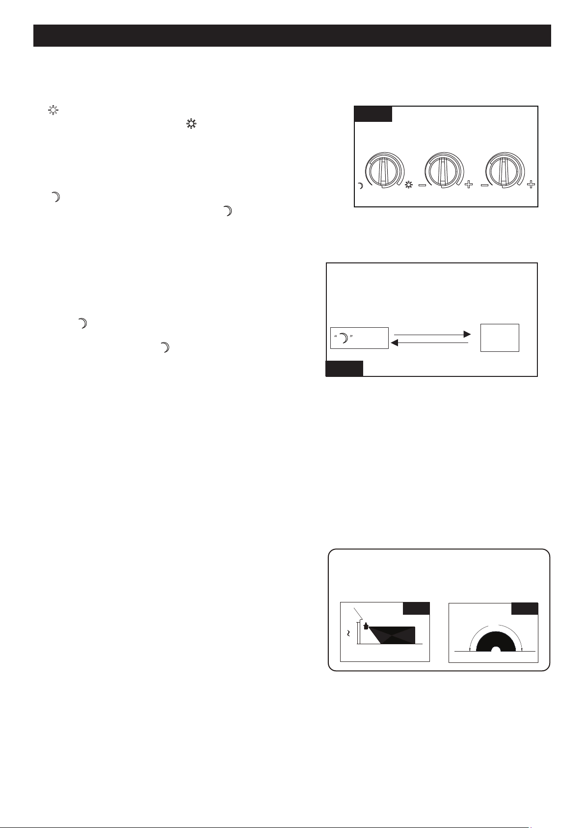
● The shut-off delay is the length of time the light will stay at brightness after motion is detected.
● You can set the shut-off delay by rotating the “TIME” knob so it points to the desired time setting (from 5
seconds to 3 minutes). To increase the shut-off delay, turn the knob clockwise. To decrease the shut-off delay,
turn the knob counterclockwise.
Shut-off Delay
Customization Options
Function and Operation
Note: When power is first applied, the light will be on. and warm up lasts 30 seconds.
1. “ ” MODE(
daytime and nighttime operation)
●
Turn the knob clockwise to“ ” position, the light turns on
after expiration of the warm-up period, It stays on when
motion is detected. When motion is no longer detected, it
remains on for the predetermined shut-off
delay time you
set (5s~3min), and then turns off automatically.
2. “ ” MODE(nighttime operation only)
● Turn the knob counter clockwise to“ ” position, the light
turns on after expiration of the warm-up period, it stays on
when motion is detected. When motion is no longer detected,
it remains on for the predetermined shut-off delay time you
set (5s~3min), and then turns off automatically.
● The light turns off automatically at dawn.
3. Manual Override MODE(nighttime operation only)
●
●
The light turns off automatically at dawn.
To shift to the manual override mode, set the mode selector
to “ ” mode. Turn the wall switch “OFF”, and turn it “ON”
twice within 3 seconds. The light will remain on all night
long. To shift back to “ ” mode, turn the wall switch “OFF”,
and turn it “ON” twice within 3 seconds again.
Note: To make sure the above functions operate properly, always keep the wall switch in the “ON” position
(including the daytime).
Fig. 3
LUX SENS TIME
Mode
Manual
Override
Manual Override Operation Diagram
Turn wall switch OFF-ON-OFF-ON
in 0.5~3 Seconds
Turn wall switch OFF-ON-OFF-ON
in 0.5~3 Seconds
Fig. 4
ASSEMBLY INSTRUCTIONS (continued)
ASSEMBLY INSTRUCTIONS (continued)
FUNCTION AND OPERATION
Page 5 of 5
ASSEMBLY INSTRUCTIONS (continued)
ASSEMBLY INSTRUCTIONS (continued)
200720
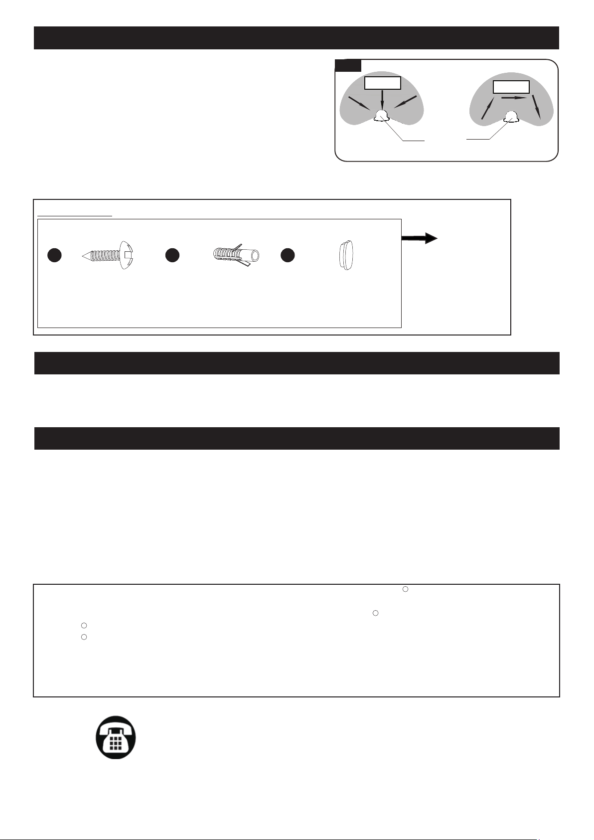
4. The sensor will be more sensitive to motion across its
detection path than motion directly towards it. (See Fig.7)
5. To reduce possible nuisances, do not mount the fixture
near a heat source like an air conditioner, vent or furnace
exhaust, or in a direction facing any reflective object or
other nearby light source.
Fig. 7
Motion
Least sensitive
Motion
Most sensitive
Sensor
Fig. 7
FUNCTION AND OPERATION (continued)
TROUBLESHOOTING
CARE AND MAINTENANCE
Clean the glass and coated metal surfaces with a non-abrasive cleaner. Do not use any cleaners with chemicals,
solvents or harsh abrasives, The motion detecting lens is coated with a specially painted finish and requires special
care when cleaning. Use only a soft dry cloth to dust or wipe the lens area.
If unable to fix any of the above issues, please consult a certified electrician.
Troubleshooting
---The light does not come on at all:
1. Make sure the wall switch and circuit breaker are on.
2. Make sure the wiring is correct.
3. Cover the sensor with dark color cloth to verify that the ambient light level is not too high.
---In Manual override, the light stays on after dawn:
1. The ambient light level may be too low due to overcast skies.
Assembly Kit
6286MM (1 SET)
Spare Parts List:
The following parts are available for reorder if damaged or missing. Call our toll free at 1-800-887-6326.
Anchor
X2
Drywall Screw
X2
AA
Decorative Cover
X2
CCBB
Questions, problems, missing parts?
Before returning to your retailer, call our customer service at 1-800-887-6326
Monday – Friday 9:00 a.m. – 5:00 p.m. CST
FIVE-YEAR LIMITED WARRANTY: If, during normal use, this PATRIOT LIGHTING lighting fixture breaks or fails
due to a defect in material workmanship within five (5) years from the date of original purchase, simply bring this
lighting fixture with the original sales receipt back to your nearest MENARDS retail store. At its discretion, PATRIOT
LIGHTING agrees to have the product or any defective part(s) repaired or replaced with the same or similar PATRIOT
LIGHTING product or part free of charge, within the stated warranty period, when returned by the original purchaser
with original sales receipt. This warranty; (1) excludes expendable parts including but not limited to light bulbs; (2) does
not cover damage that has resulted from abuse or misuse; and (3) does not cover any losses, labor, injuries to
persons/property or costs. This warranty does give you specific legal rights and you may have other rights, which vary
from state to state.
R
R
R
R