
Loading ...
Loading ...
Loading ...
EN
W415-2360 / A / 10.31.19
27
installation
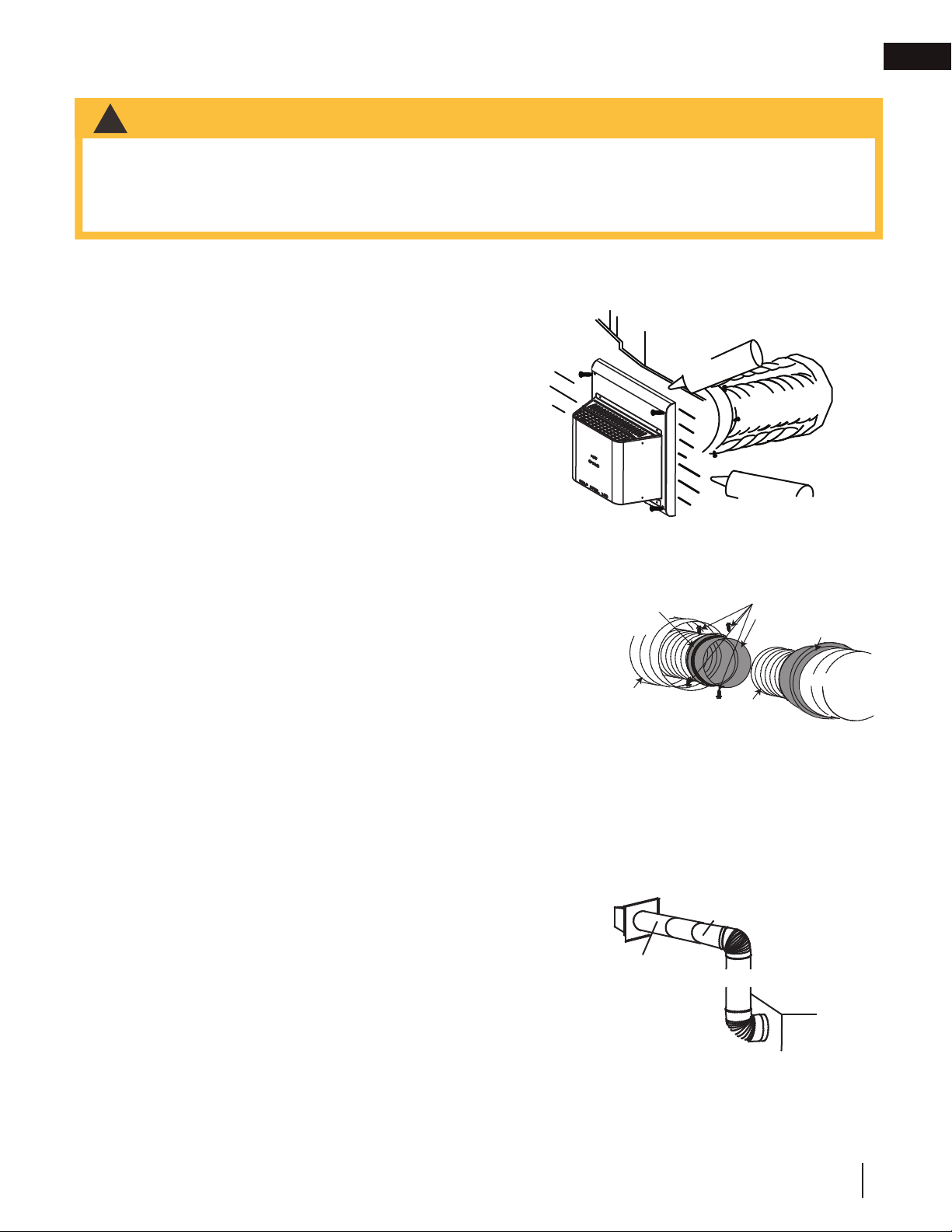
3.5 extended horizontal and corner terminal installation
All 4" (102mm) fl exible vent pipe and 7" (178mm) rigid vent pipe joints must be sealed using either high
temperature sealant W573-0002 (not supplied) or the high temperature sealant W573-0007 Mill Pac (not
supplied). However, the high temperature sealant W573-0007 Mill-Pac (not supplied) must be used on the joint
connecting the 4" (102mm) fl exible vent pipe and the exhaust fl ue collar.
A. Stretch the inner fl ex pipe to the required length taking
into account the additional length needed for the fi nished
wall surface. Apply a heavy bead of the red RTV silicone
(W573-0002) (not supplied) to the inner sleeve of the air
terminal. Slip the vent pipe a minimum of 2” (50.8mm)
over the inner sleeve of the air terminal and secure with a
minimum of 3 screws.
B. Using the outer fl ex pipe, slide over the outer combustion
air sleeve of the air terminal and secure with a minimum
of 3 screws. Seal using red RTV silicone (W573-0002)
(not supplied).
C. Insert the vent pipes through the fi restop maintaining
the required clearance to combustibles. Holding the air
terminal (lettering in an upright, readable position), secure
to the exterior wall and make weather tight by sealing
with caulking (not supplied).
D. If more vent pipe needs to be used to reach the fi replace,
couple them together, as illustrated. The vent system
must be supported approximately every 3 feet (0.9m) for
both vertical and horizontal runs. Use non-combustible
strapping to maintain the minimum clearance to
combustibles.
E. Stove Appliances Only: From inside the house, using
Red RTV Silicone (W573-0002) (not supplied), seal
between the vent pipe and the fi restop. Then slide the black trim collar over the vent pipe up to the
fi restop.
The air terminal mounting plate may be recessed into the exterior wall or siding no greater than the
depth of its return fl ange.
ADD FA
S
TENER TYP
E
ADD GRAPHIC
Screws
(Supplied)
2" (50.8mm) Overlap
Outer Flex Pipe
Inner Flex
Pipe
Red RTV Silicone
Caulking
Red RTV Silicone
Screws
Inner Coupler
Outer Coupler
Outer Flex
Pipe
Inner Flex
Pipe
Outer Flex
Pipe
!
WARNING
• Terminals must not be recessed into a wall or siding more than the depth of the return fl ange of the mounting
plate.
• Do not allow the inner fl ex pipe to bunch up on horizontal or vertical runs and elbows. Keep it pulled tight.
• Spacers are attached to the inner fl ex at pre-determined intervals to maintain an even air gap to the outer fl ex
pipe. This gap is required for safe operation. A spacer is required at the start, middle, and end of each elbow to
ensure this gap is maintained. These spacers must not be removed.
3.4 horizontal air terminal installation
FOR REAR VENT ONLY: A 45° corner installation can have 0” (0mm)
rise between the appliance combustion air collar and the air terminal.
In this case, vent lengths must be kept to a maximum of 24” (61cm).
For longer vent lengths, a minimum vertical rise of 24” (61cm) is required.
A. Follow the instructions for "horizontal air terminal installation" section.
B. Continue adding components alternating inner rigid pipe and outer
rigid pipe. Ensure that all inner rigid pipe and elbows have sufficient
vent spacers attached and each component is sealed and securely
fastened to the one prior. Attach the inner telescopic sleeve to the
vent run. Repeat using the outer telescopic sleeve. Seal and secure
as before. To facilitate completion, attach inner and outer couplers
to the air terminal.
C. Install the air terminal. See “horizontal air terminal installation” section.
Extend the outer telescopic sleeve; connect to the air terminal assembly.
Fasten with self tapping screws and seal.
Air terminal
Telescopic sleeve
20" (51cm)
Coupler
Venting
Loading ...
Loading ...
Loading ...