USER MANUAL Garage Door Opener
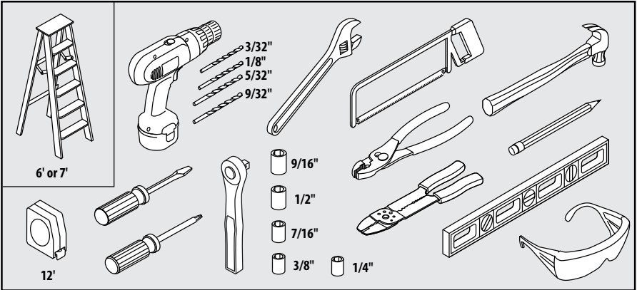
Recommended Tools
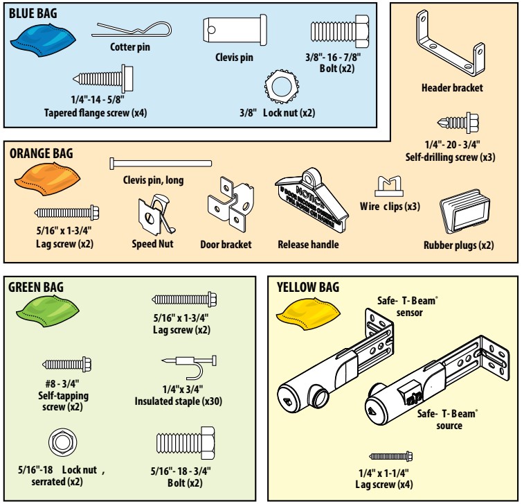
Hardware Bags
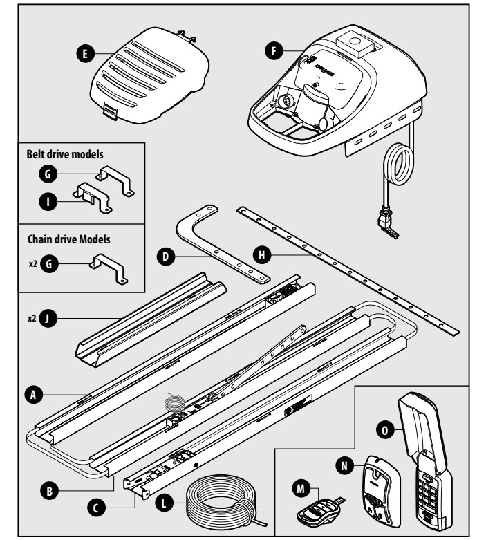
Parts Included
Parts List
(A) Powerhead end rail section
(B) Middle rail section
(C) Door end rail section
(D) Door arm, curved
(E) Powerhead lens cover
(F) Powerhead
(G) Rail mounting bracket
(H) Mounting straps
(I) Rail mounting bracket, belt drive
(J) Rail connector
(L) Safe-T-Beam and wall console wire
(M) Remote
(N) Wall console
(O) Wireless keypad (Optional on some models)
Rail Assembly (GREEN BAG) 
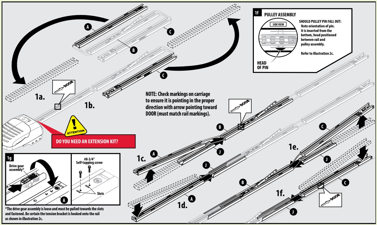
1a. Slide the powerhead end rail section (A) to correct position.
1b. Slide the door end rail section (C) to correct position.
1c. Lift powerhead rail section (A) slightly and slide rail connector (J) onto middle rail section (B).
1d. Lower powerhead rail end section (A) and slide into rail connector (J) until it locks.
1e. Lift door end rail section (C) slightly and slide rail connector (J) onto middle rail section (B).
1f. Lower door rail end section (C) and slide into rail connector (J) until it locks.
1g. Slide gear assembly to front end of powerhead end rail section (A). Ensure chain/belt is installed around gear. Turn rail assembly over and place drive gear assembly in slots. Insert two screws to fasten assembly to the rail.
ADJUSTING RAIL TENSION
2a. The chain or belt needs to be tightened inside the rail.
2b. Make sure carriage and bullet are not engaged. To disengage the carriage, pull the red cord and move carriage away from the bullet.
2c. Prior to tightening, check to make certain the tension bracket is hooked into the rail as shown in Illustration 2c. Manually tighten tension nut with wrench until chain/belt is approximately 1/8" above bottom edge of rail, measured at midpoint of rail.
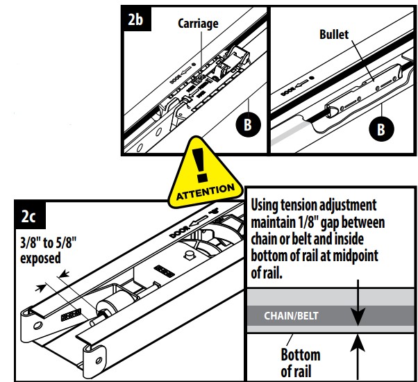
Exposed thread at tension nut (approx.):
- Belt = 3/8" to 1/2"
- Chain = 1/2" to 5/8"
ATTACH RAIL TO POWERHEAD (BLUE BAG)
|
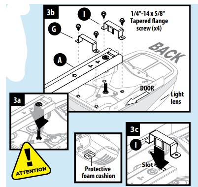
3a. Flip the rail (A) over with the open side facing down. Lower the drive gear over the spline shaft on top of the powerhead so that the powerhead's light lens is facing away from the door.
3b. Place rail mounting bracket(s) (G) over rail and align with holes in powerhead.
3c. On Belt drive models, align the tongue of the Belt Guide bracket (I) with slot and align holes in powerhead. On Chain drive models, utilize a second mounting bracket (G) and align with holes in powerhead.
3d. Fully tighten 1/4"-14 - 5/8" screws. Do not over tighten.
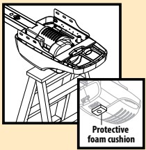
NOTE: To prevent damage to motion sensor, DO NOT remove foam cushion from underside of powerhead.
|
|
 |
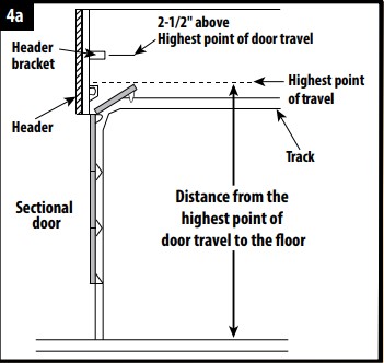
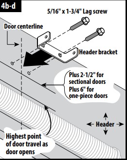
4a. Determine “highest point of door travel”:
- Get on a ladder to the side of your garage door.
- Have someone lift the door open slowly.
- As the door is raised, find the highest point where the door extends above the door tracks—that is the highest point of door travel. For sectional doors this is typically where the top door roller exits the curved portion of the track onto the horizontal section as the door is raised.
- With a tape measure, determine the distance from the highest point of door travel to the floor.
4b. Place a mark on the header at the highest point of door travel, preferably at the center of the door (measured side to side).
4c. Position the header bracket above the highest point of travel: · 2-1/2" above for sectional (hinged) doors. · 6" above for one-piece (non-hinged) doors.
4d. Drill 5/32" pilot holes in header and secure bracket with 5/16" x 1-3/4" lag screws.
| Highest Point of Door Travel |
|
Typical Installation |
 |
|
 |
ATTACHING RAIL TO BRACKET (ORANGE BAG)
|
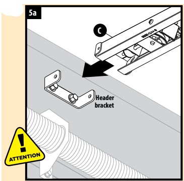
5a. Elevate powerhead assembly and position door end rail section (C) inside bracket.
NOTE: Support powerhead and have a second person assist during this step.
|
|
 |
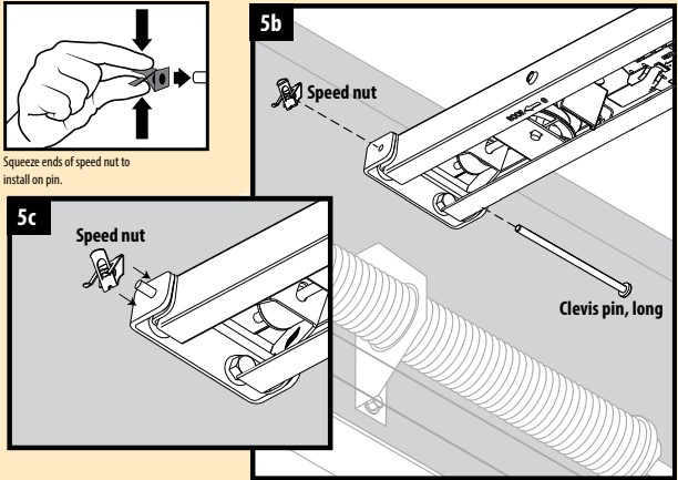
5b. Align holes in rail with holes in bracket.
5c. Slide clevis pin through holes in rail and bracket and secure with speed nut by pressing the speed nut ends together.
5d. Slide carriage near the powerhead.
MOUNTING POWERHEAD TO CEILING (GREEN BAG)
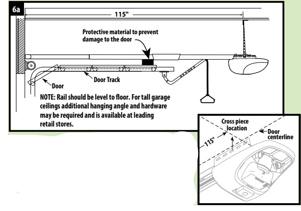
6a. If possible, lift and support powerhead while a second person fully opens the door. Insert a 2" x 4" board, cardboard or towel between door and rail, to protect door. Position powerhead over the centerline of door and allow it to rest on board. Otherwise, measure and mark ceiling 115" back from the header, aligned with the centerline of the door.
|
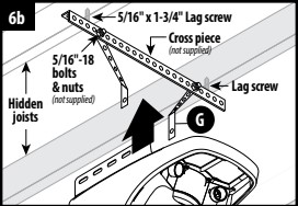
6b. Angle the mounting straps (G) and attach to joists with two 5/16" x 1-3/4" lag screws provided in the green bag. For finished ceilings, attach a cross-piece (not supplied) to joists using lag screws and secure mounting straps to the cross-piece with 5/16"-18 bolts and nuts (not supplied).
|
|
 |
6c. Raise powerhead unit so that there is sufficient clearance between door and rail. Cut or bend mounting straps as needed to align with the powerhead and level rail.
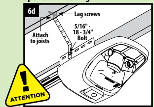
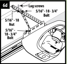
6d. Secure powerhead to mounting straps using 5/16"-18 - 3/4" bolts and nuts provided in green bag. Ensure powerhead is centered with the door and remove the 2"x 4" board and/or other protective material.
| Open Beam Ceiling |
|
Finished Ceiling |
 |
|
 |
ATTACHING DOOR BRACKET
|
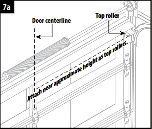
Sectional Door (Typical):
7a. Center bracket on door. Attach near approximate height as top rollers.
7b. Using bracket, mark holes on door or frame.
7c. Drill 1/8" pilot holes partially through the door.
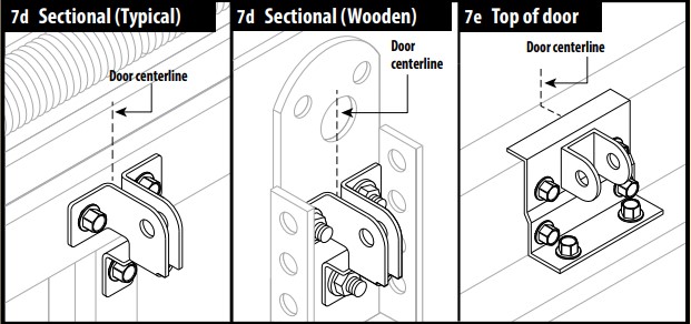
7d. Secure with 1/4" - 20 - 3/4" self-drilling screws.
7e. Some garage door manufacturers provide door brackets that CAN be used with your Genie Door Arms.
|
|
 |
Sectional Door (Wooden):
7a. Center bracket on door. Attach near approximate height as top rollers.
7b. Using bracket, mark holes on door or frame.
7c. Drill 9/32" holes completely through the door.
7d. Fasten bracket with 1/4" x 2" carriage bolts and nuts (not provided)
NOTE: One-Piece Door (Top Edge/Face Mount) instructions are in the Operation and Maintenance Manual provided.
ATTACHING DOOR ARM TO DOOR BRACKET & SHUTTLE (BLUE BAG)
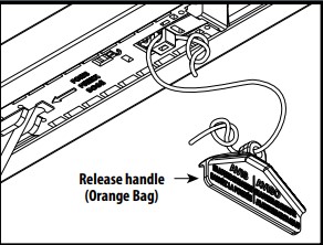
8a. Secure emergency release handle (orange bag) to cord.
8b. Using the emergency release cord, disengage the shuttle/carriage and move it toward the door, about 16" from the header.
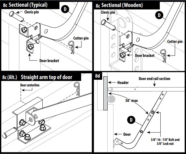
8c. Sectional Doors typically accept curved door arm (D). Install the curved door arm to the door bracket using clevis and cotter pins. In some cases, just the straight door arm may be used if the door bracket is mounted on the top edge of the door.
8d. With the door closed, attach the curved and straight door arms together using 3/8" bolts and nuts. Space the fasteners as far apart as possible.
NOTE: Overall length of both arms should be minimized, but not so short that the straight arm is vertical or exceeds 30° from the header.
NOTE: One-Piece Door (Top Edge/Face Mount) instructions are in the Operation and Maintenance Manual provided.
INSTALLING SAFE-T-BEAM® (YELLOW BAG)
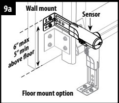
9a. Position Safe-T-Beam® (STB) source and sensor on each side of garage door 5"-6" above floor. Face the lenses towards each other.
9b. Mark bracket mounting holes; drill 3/32" pilot holes and secure with (4) 1/4 x 1-1/4" lag screws (provided) into wood. If mounting into concrete or block, other fasteners are required and are available at leading retail stores.
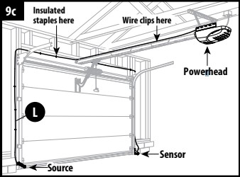
9c. Use garage pre-wiring if available. Otherwise, route 2 lengths of wire (L) from powerhead, along the rail, across the header and down both sides of the door, to each sensor. Secure the wire to the rail using the wire clips in the orange bag, evenly spaced along the rail. Then use the insulated staples to secure each wire to the wall.
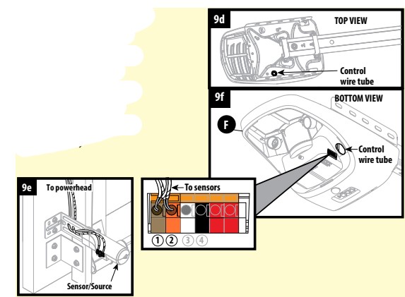
9d. On the powerhead: insert both wires down through the control wire tube. Remove 1/4" insulation from both sets of white and striped wire. Twist two white wires together. Using a small flat head screwdriver, press in the orange tab at terminal 1 and insert the wires. Twist the two striped wires together and insert into terminal 2. Ensure the wires are in their terminal; adjust as necessary.
9e. At each sensor, remove 1/4" insulation from the white and striped wires and secure in each terminal. Ensure the wires are secure at each terminal; adjust as necessary.
INSTALLING WALL CONSOLE
10a. Use garage pre-wiring if available. Otherwise, route wire (L) from powerhead to the desired location for the wall control. Secure wire with insulated staples (green bag).
10b. On the powerhead: insert wire down through the control wire tube. Remove 1/4" insulation from white and striped wire. Using a small flat head screwdriver, press in the orange tab and insert the white wire in terminal 3 and the striped wire in terminal 4. Ensure the wires are secure in each terminal; adjust as necessary.
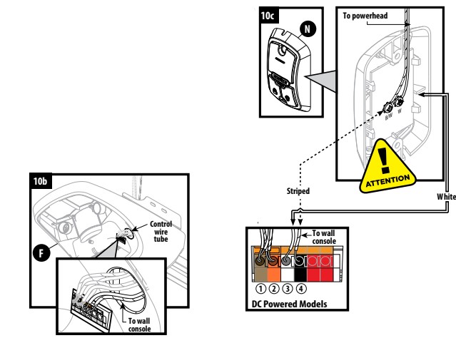
10c. At the wall console end of the wire, remove 1/4" insulation from the white and striped wires and secure the white wire to the "W" terminal and the striped wire to the "B/W" terminal as shown. Ensure the wires are secure at each terminal; adjust as necessary.
10d. Mark the wall console mounting holes, drill 3/32" pilot holes and mount with #6 - 1 - 1/4" screws (provided). If mounting to drywall, anchors will be required (not provided).
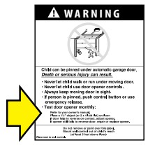
10e. Post the "ENTRAPMENT WARNING LABEL" (Included in the Operation and Maintenance Manual) next to the wall console.
NOTE: If pre-wiring is used, ensure that after power is applied to the powerhead (in Step 12), the wall console and Safe-T-Beam® LEDs come on. This confirms the wiring is correct. If not, you may need to individually wire each Safe-T-Beam® and wall console at the powerhead.
LIGHT ASSEMBLY
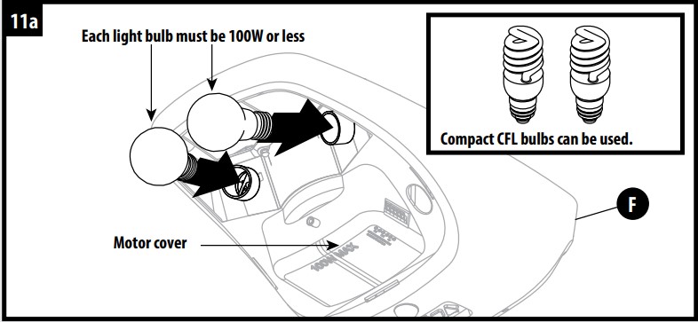
11a. Install light bulbs into powerhead (F).
NOTE: DO NOT exceed maximum wattage. Each light bulb should be no more than 100W
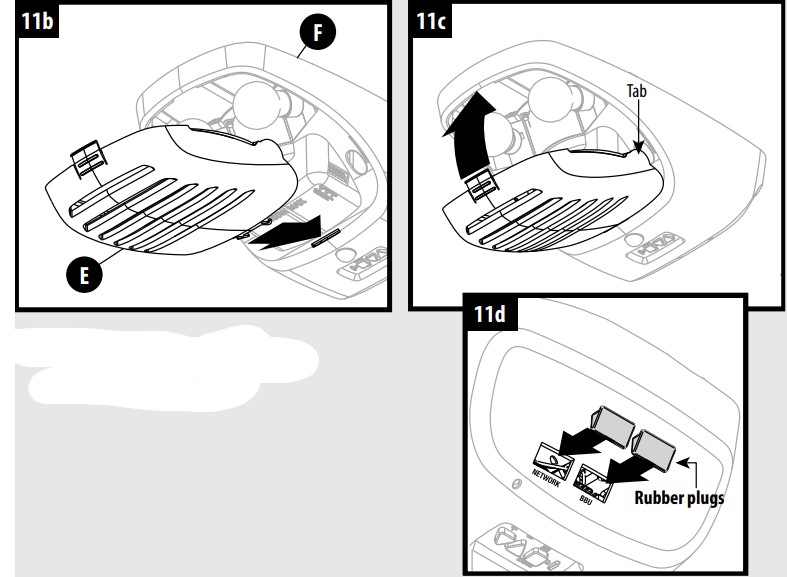
11b. Insert powerhead lens hinge (E) into slots in motor cover on powerhead (F).
11c. Swing lens (E) up into place. It may be necessary to squeeze lens slightly to align tabs with slots at top of motor cover.
11d. Insert rubber plugs (in orange bag) into powerhead accessory holes if present.
NOTE: Remove and discard foam cushion at this time.
CONNECTING POWER
For Grounded Outlet Connection:
12a. Plug in the power cord. Coil excess cord and tape or twist tie it to top of powerhead. (DO NOT PLACE ABOVE LIGHT BULBS.)
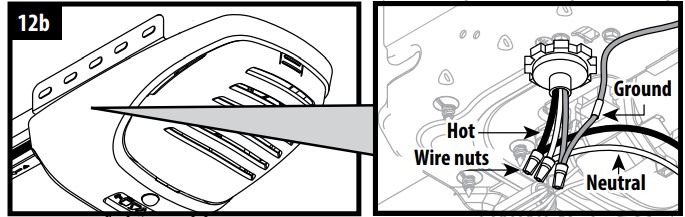
For Permanent Wiring by an Electrician:
12a. Cut existing wires OUTSIDE CHASSIS.
12b. The wire connections must be made INSIDE CHASSIS and there must be at least 6" of new power supply line wire INSIDE CHASSIS. (Conduit is optional. Conduit, strain relief, and wire nuts are not provided.)
NOTE: After power is supplied to the powerhead: (1) Check if the red and green Safe-T-Beam® LEDs are lit. If not, return to step 9 and check wiring. (2) See if wall console red LED is lit. If not, check if a blue LED on powerhead is blinking. If yes, press the "LOCK" button on the wall console. (Wall console LED should now be lit.) Otherwise, return to step 10 and check wiring.