Loading ...
Loading ...
Loading ...
11
PLEASE NOTE: EL22 IS FOR OUTDOOR PERMANENT INSTALLATIONS ONLY AND EL22-I IS FOR INDOOR PERMANENT INSTALLATIONS ONLY. THIS MANUAL
AND ALL ECCOTEMP CONTENT IS SUBJECT TO CHANGE WITHOUT NOTICE. PLEASE VISIT WWW.ECCOTEMP.COM/SUPPORT FOR MORE INFORMATION.
Support: Eccotemp.com/help-desk Shop Online: Eccotemp.com/products Store Locator: Eccotemp.com/locator
Phone: 866-356-1992 | Email: [email protected] | Address: 315 - A Industrial RD Summerville, SC 29483
English
Water Supply Connections Continued
If a water heater is installed in a closed water supply system, such as
one having a backow preventer in the cold water supply line, means
shall be provided to control thermal expansion. Contact the water
supplier or local plumbing inspector on how to control this situation.
Install a shuto valve near the inlet of the water heater for service and
draining purposes.
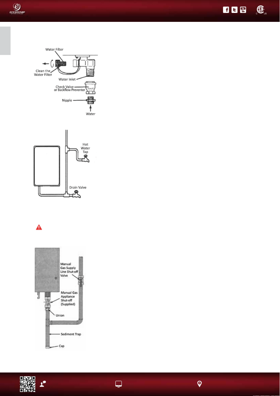
Before connecting the water supply pipe to the water heater, open
the shuto valve ·and clean out sand, debris, air, caulking material,
etc. inside the pipe. Connect to the water inlet, then check water ow.
Close the shuto valve and clean the water lter.
Be sure to connect the water inlet and the hot water outlet as shown
on the water heater. If reversed, the water heater will not function.
Installation of unions or exible copper connections are
recommended on the HOT and COLD water lines, so that the water
heater may disconnect easily for servicing if necessary.
Install a Check Valve between the water heater and the water shuto
valve. (See illustration to the top left).
In regards to the HOT WATER OUTLET:
Connections between the water heater and point(s) of use should be
as short and direct as possible.
DO NOT use lead or non-approved plastic pipe.
NOTICE: The ow rate of hot water may vary when more than two
faucets (appliances, xtures, etc.) are being used simultaneously.
NOTICE: The pipes MUST be completely drainable. If the hot water faucets are located at a point higher
than the water heater, place a drain valve at the lowest point (see illustration to the bottom left).
Gas Supply
WARNING: Do not attempt to convert this water heater for use with a dierent type of
gas other than the type shown on the rating plate. Such conversion could result in hazardous
operating conditions. Please have a professional connect the gas pipe.
A Manual Gas Appliance Shuto
Valve must be installed at the gas
connection of the water heater at the
time of installation (see diagram to
the left). The branch gas supply line to
the water heater should be clean black
steel pipe or other approved gas piping
material.
A ground joint union or ANSI design
certied semi-rigid or exible gas
appliance connector should be
installed in the gas line close to the
water heater. The National Fuel Gas
Code (NFGC) mandates a manual gas
shut-o valve: See (NFGC) for complete
instructions.
If exible connectors are used, the
maximum length shall not exceed 36”.
If lever type gas shut os are used, they
shall be T-Handle type.
Compound used on the threaded
joints of the gas piping must be of
the type resistant to the action of LP
gas. Use compound sparingly on male
threads only.
A sediment trap should be installed
at the bottom of the gas line.
Do not use excessive force (over
31.5 ft lbs.) in tightening the pipe,
particularly if pipe-tape compound
is used, as the unit may be damaged.
The inlet gas pressure to the water
heater must not exceed 10.5 “ w.c.
for natural or 14” w.c. for LP gas. For
purposes of input adjustment, the
minimum inlet gas pressure (with
main burner on) is shown on the
water heater rating plate. If high or
low gas pressures are present, contact
your gas supplier for correction.
EL22
Loading ...
Loading ...
Loading ...