OWNER’S MANUAL Gas Range
RANGE MAINTENANCE AND CARE
General Cleaning
- IMPORTANT: Before cleaning, make sure all controls are OFF and the oven and cooktop are cool. Always follow label instructions on cleaning products.
- Soap, water, and a soft cloth or sponge are suggested first, unless otherwise noted.
EXTERIOR PORCELAIN ENAMEL SURFACES (on some models): Food spills containing acids, such as vinegar and tomato, should be cleaned as soon as the entire range is cool. These spills may affect the finish. Cleaning Method:
- Glass cleaner, mild liquid cleaner, or nonabrasive scrubbing pad: Gently clean around the model/serial/rating plate because scrubbing may remove numbers.
- Affresh®† Kitchen and Appliance Cleaner Part Number W10355010 (not included): See the Quick Start Guide for ordering information.
STAINLESS STEEL (on some models) - NOTE: To avoid damage to stainless steel surfaces, do not use soap-filled scouring pads, abrasive cleaners, Cooktop Cleaner, steel-wool pads, gritty washcloths, or abrasive paper towels. Damage may occur to stainless steel surfaces, even with one-time or limited use. Cleaning Method:
- Rub in direction of grain to avoid damaging.
- Affresh® Stainless Steel Cleaner Part Number W10355016 (not included): See the Quick Start Guide for ordering information.
Yellow Heat Stains:
- Add 1 tbs (15 mL) of table salt to 1/4 cup (59.1 mL) of vinegar, and then stir for 1 minute. Not all of the salt will dissolve.
- Using a soft cloth, soak up the liquid of the vinegar mixture. Dab the wet cloth onto the yellow stains for 3 to 4 minutes. The wetter the stainless steel is, the better the cleaning results will be.
- Let sit until the yellow stains have faded. Using a dry soft cloth, wipe off the remaining vinegar mixture.
- Repeat steps 1 to 3 until all yellow stains have been removed.
- Using clean water and a fresh soft cloth, clean off any remaining residue. Dry with a clean soft cloth.
- Use affresh® Stainless Steel Cleaner Part Number W10355016 (not included) to protect and polish the cleaned surface.
NOTE: Remove surface grates before cleaning rear vent trim. Avoid dripping the vinegar mixture into the vent holes or down the back of the range.
METALLIC PAINT (on some models)
- Do not use abrasive cleaners, cleaners with bleach, rust removers, ammonia, or sodium hydroxide (lye) because paint surface may stain.
PORCELAIN-COATED GRATES AND CAPS
- Food spills containing acids, such as vinegar and tomato, should be cleaned as soon as the cooktop, grates and caps are cool. These spills may affect the finish.
- To avoid chipping, do not bang grates, and caps against each other or hard surfaces such as cast iron cookware.
- Do not reassemble caps on burners while wet. Do not clean in the Self-Cleaning cycle.
- Cleaning Method:
- Nonabrasive plastic scrubbing pad and mildly abrasive cleanser: Clean as soon as cooktop, grates, and caps are cool.
- Dishwasher (grates only, not caps): Use the most-aggressive cycle. Cooked-on soils should be soaked or scrubbed before going into a dishwasher. Although the burner grates are durable, they may lose their shine and/or discolor when washed in a dishwasher.
- Gas Grate and Drip Pan Cleaner Part Number 31617 (not included): See the Quick Start Guide for ordering information.
SURFACE BURNERS: Food spills containing acids, such as vinegar and tomato, should be cleaned as soon as the cooktop, grates, and caps are cool. These spills may affect the finish. To avoid chipping, do not bang grates and caps against each other or hard surfaces such as cast iron cookware. Do not reassemble caps on burners while wet. Do not clean in the Self-Cleaning cycle. Do not clean in dishwasher. Cleaning Method:
- Nonabrasive plastic scrubbing pad and mildly abrasive cleanser: Clean as soon as cooktop, grates, burners, and caps are cool.
- Gas Grate and Drip Pan Cleaner (not included).
COOKTOP CONTROLS: To avoid damage to the cooktop controls, do not use steel wool, abrasive cleansers, or oven cleaner. To avoid damage, do not soak knobs. When replacing knobs, make sure knobs are in the Off position. On some models, do not remove seals under knobs. Cleaning Method:
- Soap and water: Pull knobs straight away from control panel to remove
GRIDDLE (on some models): To avoid damaging the nonstick surface, do not use steel wool or abrasive cleaners. Cleaning Method:
- Mild detergent
- Dishwasher: Although the griddle is durable, it may lose its shine and/or is color when washed in a dishwasher.
CONTROL PANEL AND OVEN DOOR EXTERIOR: To avoid damage to the control panel, do not use abrasive cleaners, steel-wool pads, gritty washcloths, or abrasive paper towels. Cleaning Method:
- Glass cleaner and soft cloth or sponge: Apply glass cleaner to soft cloth or sponge, not directly on panel.
- Affresh® Kitchen and Appliance Cleaner Part Number W10355010 (not included): See the Quick Start Guide for ordering information.
OVEN RACKS
Cleaning Method:
- Steel-wool pad
- For racks that have discolored and are harder to slide, a light coating of vegetable oil applied to the rack guides will help them slide.
- Dishwasher (steam rack water reservoir only, not racks): Although the water reservoir is durable, it may lose its shine and/or discolor when washed in a dishwasher
BAKING DRAWER (on some models): Check that baking drawer is cool and empty before cleaning. Food spills should be cleaned when oven cools. At high temperatures, foods react with porcelain. Staining, etching, pitting, or faint white spots can result. Cleaning Method:
STORAGE/WARMING DRAWER (on some models): Check that storage/warming drawer is cool and empty before cleaning. Cleaning Method:
OVEN CAVITY: Use AquaLift® Technology regularly to clean oven spills. Do not use oven cleaners. Food spills should be cleaned when oven cools. At high temperatures, foods react with porcelain. Staining, etching, pitting, or faint white spots can result. Cleaning Method:
- Self-Cleaning cycle: See the “Self-Cleaning Cycle” or “Clean Cycle” section first.
Clean Cycle

- AquaLift® Technology is an innovative cleaning solution that utilizes heat and water to release baked-on spills from the oven in less than 1 hour. This new cleaning technology is a low-heat, odor-free alternative to traditional self-cleaning options.
- Allow the oven to cool to room temperature before using the Clean cycle. If your oven cavity is above 200°F (93°C), it will appear in the display, and the Clean cycle will not be activated until the oven cavity cools down.
To Clean:
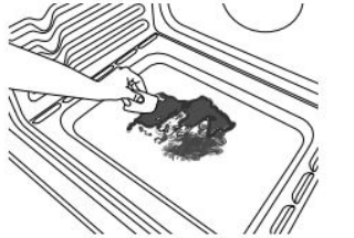
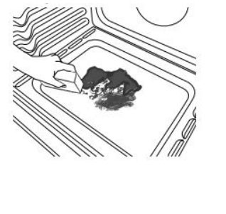
1. Remove all racks and accessories from the oven cavity, and wipe excess soil. Use a plastic scraper to remove easily removed soils
2. Pour 13/4 cups (14 oz [414 mL]) of distilled or filtered water onto the bottom of the empty oven, and close the oven door.
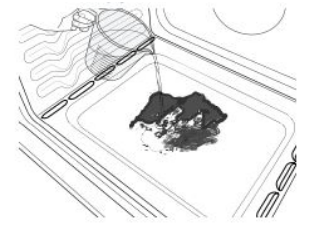
IMPORTANT: Do not use chemicals or other additives with the water. Do not open the oven door during the Clean cycle. The water on the oven bottom is hot.
3. Press CLEAN/AQUALIFT SELF CLEAN and then STARTon the oven control panel.
4. Allow 40 minutes for cleaning and cooldown. A beep will sound when the Clean cycle is complete
. 5. Press OFF/CANCEL/CANCEL UPPER at the end of the cycle. Off/Cancel/Cancel Upper may be pressed at any time to stop the Clean cycle.
6. Remove the residual water and loosened soils with a sponge or cloth immediately after the Clean cycle is complete. Much of the initial 13/4 cups (14 oz [414 mL]) of water will remain in the oven after the cycle is completed. If additional soils remain, leave a small amount of water in the oven bottom to assist with the cleaning.
7. If any soils remain, remove them with a nonscratch scrubbing sponge or plastic scraper. Additional Clean cycles may be run to help remove the stubborn soils.
IMPORTANT: Do not use oven cleaners. The use of chemicals, including commercial oven cleaners or metal scouring pads, may cause permanent damage to the porcelain surface of the oven interior.
NOTE:
- The range should be level to ensure that the entire surface of the bottom of the oven cavity is covered by water at the beginning of the Clean cycle.
- For best results, use distilled or filtered water. Tap water may leave mineral deposits on the oven bottom.
- Before removing the residual water and loosened soils at the end of the Clean cycle, insert a cloth or paper towel between the lower edge of the oven door and the front frame to keep water from spilling onto the front of the range and the floor.
- Soil baked on through several cooking cycles will be more difficult to remove with the Clean cycle.
- Nonabrasive scrub sponges or eraser-style cleaning pads (without cleaners) can be effective for cleaning the oven cavity walls, oven door, and oven bottom for difficult soils. For best results, moisten the pads and sponges before use.
- Run an additional Clean cycle for stubborn soils
- Affresh® Kitchen Appliance Cleaner and affresh® Cooktop Cleaner may be used to clean the oven bottom, walls, and door when the oven has finished the cycle and returned to room temperature. If affresh® Cooktop Cleaner is used, it is recommended to wipe out the cavity with distilled water as well. Refer to the Quick Start Guide for ordering information.
- Additional AquaLift® Technology Cleaning Kits may be obtained by ordering Part Number W10423113RP. Refer to the Quick Start Guide for ordering information.
INSTALLATION INSTRUCTIONS
REQUIREMENTS
Tools and Parts
Gather the required tools and parts before starting installation. Read and follow the instructions provided with any tools listed here.
Tools Needed
- Tape measure
- Flat-blade screwdriver
- Phillips screwdriver
- 1/8" flat-blade screwdriver Level
- Hand or electric drill
- Hammer
- Wrench or pliers
- Pipe wrench
- 15/16" combination wrench
- 1/4" drive ratchet
- 3/8" nut driver
- 1/8" drill bit (for wood floors)
- Marker or pencil
- Pipe-joint compound resistant to Propane gas
- Noncorrosive leak-detection solution
- 3/16" carbide-tipped masonry drill bit (for concrete/ceramic floors) (For Slide-in/Front Control Ranges)
For Propane/Natural Gas Conversions
- 3/8" combination wrench
- 1/2" combination wrench
- 5/8" combination wrench
- 9/32" nut driver
- Quadrex®† or Phillips screwdriver
- Masking tape
- 3/8" nut driver (For Slide-in/Front Control Ranges)
Parts Supplied Check that all parts are included.
- Propane/Natural Gas Conversion Kit
- #10 x 15/8" (4.1 cm) screws (for mounting anti-tip bracket) (2)
- Anti-tip bracket (inside oven cavity)
Anti-tip bracket must be securely mounted to the back wall or floor. Thickness of flooring may require longer screws to anchor bracket to subfloor. Longer screws are available from your local hardware store.
Parts needed
- Check local codes and consult gas supplier. Check existing gas supply and electrical supply. See “Electrical Requirements” and “Gas Supply Requirements” sections.
- IMPORTANT: When the range is used under microwave models: JMC82808CB-0, JMV9196CB-0, or YJMV9196CB-0, the Door Baffle Plate Part Number W10737014 must be ordered and used. Please reference the Quick Start Guide for contact information.
- Optional parts: To purchase these or any other accessories, please reference the Quick Start Guide for contact information.
- Side Trim Kits: 5/8" (1.7 cm) White - Order Part Number W10675027 5/8" (1.7 cm) Black - Order Part Number W10675026 5/8" (1.7 cm) Stainless Steel - Order Part Number W10675028 11/8" (2.9 cm) White - Order Part Number W10731885 11/8" (2.9 cm) Black - Order Part Number W10731886 11/8" (2.9 cm) Stainless Steel - Order Part Number W10731887
- Backsplash Kits: High 6" (15.2 cm) White - Order Part Number W10655448 High 6" (15.2 cm) Black - Order Part Number W10655449 High 6" (15.2 cm) Stainless Steel - Order Part Number W10655450
NOTE: Be sure to purchase only whirlpool factory-certified parts and accessories for your appliance. Your installation may require additional parts. To order, refer to the contact information referenced in your Quick Start Guide.
Location Requirements
IMPORTANT: Observe all governing codes and ordinances. Do not obstruct flow of combustion and ventilation air.
- It is the installer’s responsibility to comply with installation clearances specified on the model/serial/rating plate. The model/serial/rating plate is located behind the oven door on the top right/left-hand side of the oven frame.
- The range should be located for convenient use in the kitchen.
- Recessed installations must provide complete enclosure of the sides and rear of the range.
- All openings in the wall or floor where range is to be installed must be sealed.
- Cabinet opening dimensions that are shown must be used. Given dimensions are minimum clearances.
- The anti-tip bracket must be installed. To install the anti-tip bracket shipped with the range, see “Install Anti-Tip Bracket” section.
- Grounded electrical supply is required. See “Electrical Requirements” section.
- Proper gas supply connection must be available. See “Gas Supply Requirements” section.
- Contact a qualified floor covering installer to check that the floor covering can withstand at least 200°F (93°C).
- Use an insulated pad or 1/4" (6.4 mm) plywood under range if installing range over carpeting.
IMPORTANT: To avoid damage to your cabinets, check with your builder or cabinet supplier to make sure that the materials used will not discolor, delaminate or sustain other damage. This oven has been designed in accordance with the requirements of UL and CSA International and complies with the maximum allowable wood cabinet temperatures of 194°F (90°C)
Mobile Home - Additional Installation Requirements: The installation of this range must conform to the Manufactured Home Construction and Safety Standard, Title 24 CFR, Part 3280 (formerly the Federal Standard for Mobile Home Construction and Safety, Title 24, HUD Part 280). When such standard is not applicable, use the Standard for Manufactured Home Installations, ANSI A225.1/NFPA 501A or with local codes. In Canada, the installation of this range must conform with the current standards CAN/CSA-Z240.1, latest edition, or with local codes. Mobile Home Installations Require:
- When this range is installed in a mobile home, it must be secured to the floor during transit. Any method of securing the range is adequate as long as it conforms to the standards listed above.
Cabinet Dimensions:
- Cabinet opening dimensions shown are for 25" (64.0 cm) countertop depth, 24" (61.0 cm) base cabinet depth and 36" (91.4 cm) countertop height.
- IMPORTANT: If installing a range hood or microwave hood combination above the range, follow the range hood or microwave hood combination installation instructions for dimensional clearances above the cooktop surface.
- NOTE: When installed in a slide-in cutout, the front of oven door may protrude beyond the base cabinet.
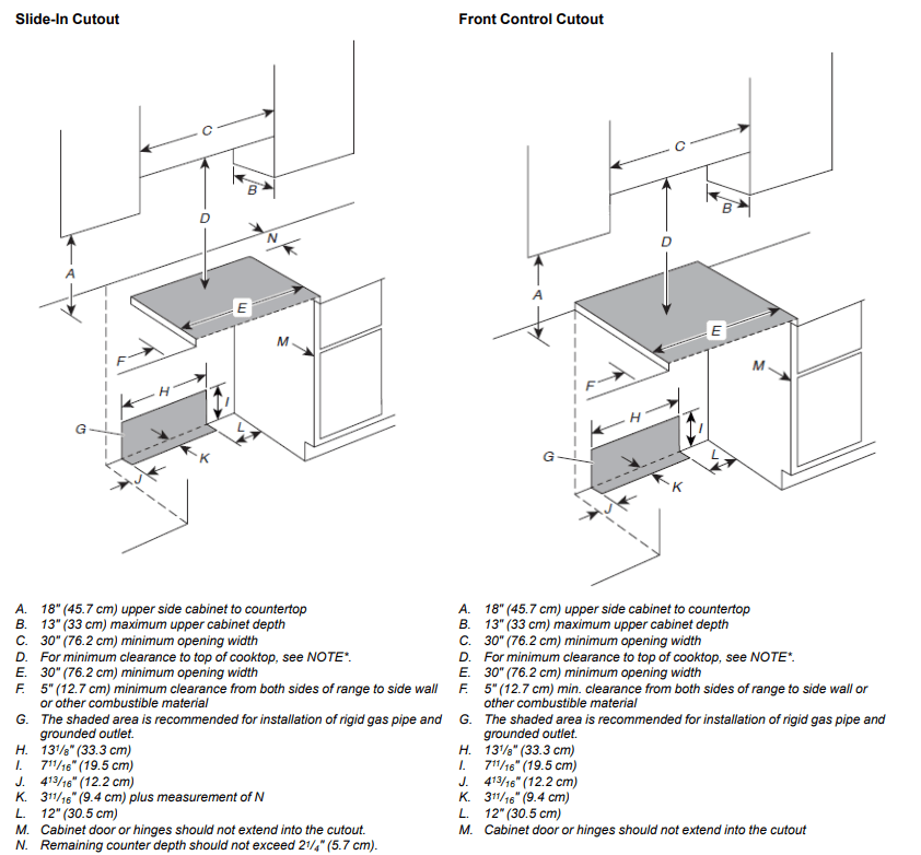
*NOTE : 24" (61.0 cm) minimum when bottom of wood or metal cabinet is shielded by not less than 1/4" (6.35 mm) flame retardant millboard covered with not less than No. 28 MSG sheet steel, 0.015" (0.4 mm) stainless steel, 0.024" (0.6 mm) aluminum or 0.020" (0.5 mm) copper. 30" (76.2 cm) minimum clearance between the top of the cooking platform and the bottom of an uncovered wood or metal cabinet.
Electrical Requirements
- IMPORTANT: The range must be electrically grounded in accordance with local codes and ordinances, or in the absence of local codes, with the National Electrical Code, ANSI/NFPA 70 or Canadian Electrical Code, CSA C22.1.
- This range is equipped with an electronic ignition system that will not operate if plugged into an outlet that is not properly polarized.
- If codes permit and a separate ground wire is used, it is recommended that a qualified electrical installer determine that the ground path is adequate.
A copy of the above code standards can be obtained from: National Fire Protection Association 1 Batterymarch Park Quincy, MA 02169-7471 CSA International 8501 East Pleasant Valley Road Cleveland, OH 44131-5575
- A 120 V, 60 Hz, AC only, 15 A fused, ground and polarized electrical circuit is required. A time-delay fuse or circuit breaker is also recommended. It is recommended that a separate circuit serving only this range be provided.
- Electronic ignition systems operate within wide voltage limits, but proper grounding and polarity are necessary. Check that the outlet provides 120 V power and is correctly grounded.
- This gas range is not required to be plugged into a GFCI (Ground-Fault Circuit Interrupter) outlet. It is recommended that you not plug an electric spark ignition gas range or any other major appliance into a GFCI wall outlet as it may cause the GFCI to trip during normal cycling.
- Performance of this range will not be affected if operated on a GFCI-protected circuit. However, occasional nuisance tripping of the GFCI breaker is possible due to the normal operating nature of electronic gas ranges.
- The tech sheet and wiring diagram are located on the back of the range in a plastic bag.
NOTE: The metal chassis of the range must be grounded in order for the control panel to work. If the metal chassis of the range is not grounded, no keypads will operate. Check with a qualified electrician if you are in doubt as to whether the metal chassis of the range is grounded.
Gas Supply Requirements
- Observe all governing codes and ordinances.
- IMPORTANT: This installation must conform with all local codes and ordinances. In the absence of local codes, installation must conform with the National Fuel Gas Code ANSI Z223.1/NFPA 54 or, in Canada, the Natural Gas and Propane Installation Code, CSA B149.1 - latest edition.
- IMPORTANT: Leak testing of the range must be conducted according to the manufacturer’s instructions. Refer to the “Complete Connection” in the “Make gas connection” section for the leak testing instructions
Type of Gas
- Natural Gas: This range is factory set for use with Natural gas. See “Gas Conversions” section. The model/serial rating plate located on the oven frame behind of the oven door has information on the types of gas that can be used. If the types of gas listed do not include the type of gas available, check with the local gas supplier.
- Propane Gas Conversion: Conversion must be done by a qualified service technician. No attempt shall be made to convert the appliance from the gas specified on the model/serial rating plate for use with a different gas without consulting the serving gas supplier. See “Gas Conversions” section.
Gas Supply Line
- Provide a gas supply line of 3/4" (1.9 cm) rigid pipe to the range location. A smaller size pipe on longer runs may result in insufficient gas supply. With Propane gas, piping or tubing size can be 1/2" (1.3 cm) minimum. Usually, Propane gas suppliers determine the size and materials used in the system.
- NOTE: Pipe-joint compounds that resist the action of Propane gas must be used. Do not use TEFLON®† tape.
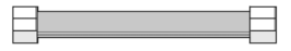
Flexible Metal Appliance Connector:
- If local codes permit, a new CSA design-certified, 4 to 5 ft (122 to 152.4 cm) long, 1/2" (13 mm) or 3/4" (19 mm) I.D., flexible metal appliance connector may be used for connecting range to the gas supply line.
- A 1/2" (13 mm) male pipe thread is needed for connection to the female pipe threads of the inlet to the appliance pressure regulator.
- Do not kink or damage the flexible metal tubing when moving the range.
Rigid pipe connection: The rigid pipe connection requires a combination of pipe fittings to obtain an in-line connection to the range. The rigid pipe must be level with the range connection. All strains must be removed from the supply and fuel lines so range will be level and in line.
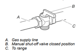
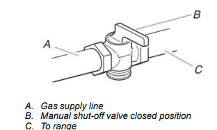
- Must include a shut-off valve: Install a manual gas line shut-off valve in an easily accessible location. Do not block access to shut-off valve. The valve is for turning on or shutting off gas to the cooktop.
Gas Pressure Regulator
- The gas pressure regulator supplied with this range must be used. The inlet pressure to the regulator should be as follows for proper operation:
- Natural Gas: Minimum pressure: 5" (12.7 cm) WCP Maximum pressure: 14" (35.5 cm) WCP
- Propane Gas: Minimum pressure: 11" (27.9 cm) WCP Maximum pressure: 14" (35.5 cm) WCP Contact local gas supplier if you are not sure about the inlet pressure.
Burner Input Requirements
- Input ratings shown on the model/serial/rating plate are for elevations up to 2,000 ft (609.6 m).
- For elevations above 2,000 ft (609.6 m), ratings are reduced at a rate of 4% for each 1,000 ft (304.8 m) above sea level (not applicable for Canada).
Gas Supply Pressure Testing
- Gas supply pressure for testing regulator must be at least 1" (2.5 cm) water column pressure above the manifold pressure shown on the model/serial rating plate.
- Line pressure testing above 1/2 psi (3.5 kPa) gauge 14" (35.5 cm) WCP The range and its individual shutoff valve must be disconnected from the gas supply piping system during any pressure testing of that system at test pressures in excess of 1/2 psi (3.5 kPa).
- Line pressure testing at 1/2 psi (3.5 kPa) gauge 14" (35.5 cm) WCP or lower The range must be isolated from the gas supply piping system by closing its individual manual shutoff valve during any pressure testing of the gas supply piping system at test pressures equal to or less than 1/2 psi (3.5 kPa).
INSTALLATION
Unpack Range
- Remove shipping materials, tape and film from the range. Keep cardboard bottom under range. Do not dispose of anything until the installation is complete.
- Remove oven racks and parts package from oven and shipping materials.
- To remove cardboard bottom, first take four cardboard corners from the carton. Stack one cardboard corner on top of another. Repeat with the other two corners. Place them lengthwise on the floor behind the range to support the range when it is laid on its back.
- Using two or more people, firmly grasp the range and gently lay it on its back on the cardboard corners.
- Remove cardboard bottom.
The leveling legs can be adjusted while the range is on its back. See the “Adjust Leveling Legs” section.
NOTE: To place range back up into a standing position, put a sheet of cardboard or hardboard on the floor in front of range to protect the flooring. Using two or more people, stand range back up onto the cardboard or hardboard.
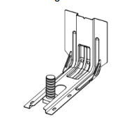
Install Anti-Tip Bracket
1. Remove the anti-tip bracket from the inside of the oven.
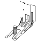
2. Determine which mounting method to use: floor or wall. If you have a stone or masonry floor, you can use the wall mounting method. If you are installing the range in a mobile home, you must secure the range to the floor. This anti-tip bracket and screws can be used with wood or metal studs.
3. Determine and mark centerline of the cutout space. The mounting bracket can be installed on either the left-hand or right-hand side of the cutout. Position mounting bracket against the wall in the cutout so that the V-notch of the bracket is 121/2" (31.8 cm) from centerline, as shown.
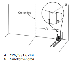
4. Drill two 1/8" (3 mm) holes that correspond to the bracket holes of the determined mounting method. See the following illustrations.
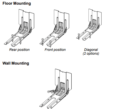
5. Using the two #10 x 15/8" (41 mm) Phillips-head screws provided, mount anti-tip bracket to the wall or floor.
6. Move range close enough to opening to allow for final electrical connections. Remove shipping base, cardboard or hardboard from under range.
7. Move range into its final location, making sure rear leveling leg slides into anti-tip bracket.
8. Move range forward onto shipping base, cardboard, or hardboard to continue installing the range, using the following installation instructions.
Adjust Leveling Legs
- If range height adjustment is necessary, use a wrench or pliers to loosen the four leveling legs. This may be done with the range on its back or with the range supported on two legs after the range has been placed back to a standing position. NOTE: To place range back up into a standing position, put a sheet of cardboard or hardboard in front of range. Using two or more people, stand range back up onto the cardboard or hardboard.
- Measure the distance from the top of the counter to the floor.
- Measure the distance from the top of the cooktop to the bottom of the leveling legs. This distance should be the same. If it is not, adjust the leveling legs to the correct height. The leveling legs can be loosened to add up to a maximum of 1" (2.5 cm). A minimum of 3/16" (5 mm) is needed to engage the anti-tip bracket. NOTE: If height adjustment is made when range is standing, tilt the range back to adjust the front legs, and then tilt forward to adjust the rear legs.
- When the range is at the correct height, check that there is adequate clearance under the range for the anti-tip bracket. Before sliding range into its final location, check that the antitip bracket will slide under the range and onto the rear leveling leg prior to anti-tip bracket installation. NOTE: If a Trim Kit will be used, the top of the cooktop should be higher than the counter. See the Installation Instructions included with the Trim Kit for the correct height.
Level Range
1. Place level on the oven bottom, as indicated in one of the two figures below, depending on the size of the level. Check with the level side to side and front to back.
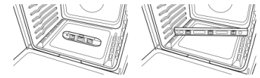
2. If range is not level, use a wrench or pliers to adjust leveling legs up or down until the range is level. NOTE: Range must be level for satisfactory baking performance and best cleaning results using AquaLift® SelfClean Technology
Make Gas Connection
This range is factory-set for use with Natural gas. To use this range with propane gas, see the “Gas Conversions” section before connecting this range to the gas supply. Gas conversions from Natural gas to Propane gas or from Propane gas to Natural gas must be done by a qualified installer.
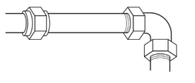
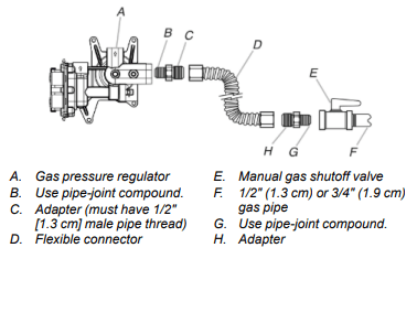
Typical flexible connection
- Apply pipe-joint compound made for use with Propane gas to the smaller thread ends of the flexible connector adapters (see B and G in the following illustration).
- Attach one adapter to the gas pressure regulator and the other adapter to the gas shutoff valve. Tighten both adapters, being certain not to move or turn the gas pressure regulator.
- Use a 15/16" (2.4 cm) combination wrench and an adjustable wrench to attach the flexible connector to the adapters. IMPORTANT: All connections must be wrench-tightened. Do not make connections to the gas regulator too tight. Making the connections too tight may crack the regulator and cause a gas leak. Do not allow the regulator to turn when tightening fittings.
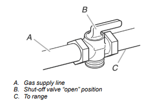
Complete Connection
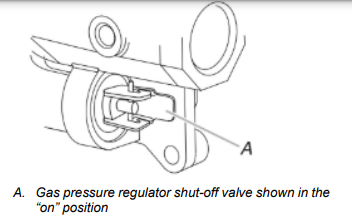
1. Check that the gas pressure regulator shut-off valve is in the “on” position.
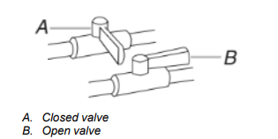
2. Open the manual shut-off valve in the gas supply line. The valve is open when the handle is parallel to the gas pipe.
3. Test all connections by brushing on an approved noncorrosive leak-detection solution. If bubbles appear, a leak is indicated. Correct any leak found.
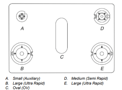
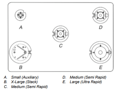
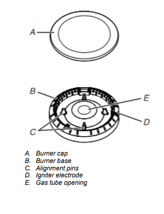
4. Remove cooktop burner caps and bases from package containing parts. Place the burner bases as indicated by the following illustration for your model:
For models WEG745H0F and MGS8800F:
For model KSGG700E:
For model KSGB900E:
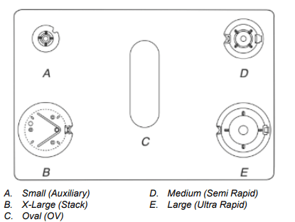
NOTE: Each round burner base is marked with one of the following: AUX, SR, UR, ST.
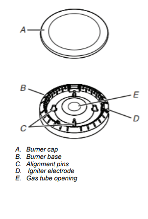
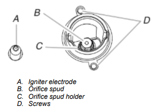
5. Align the gas tube opening in the burner base with the orifice holder on the cooktop and the igniter electrode with the notch in the burner base.
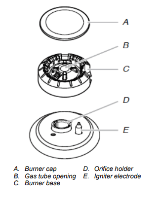
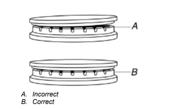
6. Place the burner caps on the appropriate burner bases. IMPORTANT: The bottom of the small and medium caps are different. Do not put the wrong size burner cap on the burner base. Each round burner cap is marked with an AUX, SR, UR, or ST to match with a letter on the burner base
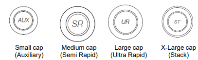
Burner caps should be level when properly positioned. If burner caps are not properly positioned, surface burners will not light. The burner cap should not rock or wobble when properly aligned.
7. Plug into a grounded 3-prong outlet.
Verify Anti-Tip Bracket Is Installed and Engaged
On Ranges Equipped with a Premium Storage Drawer:
- Slide range into final location, making sure rear leveling leg slides into anti-tip bracket.
- Remove the premium storage drawer. See the “Remove/ Replace Drawer” section.
- Use a flashlight to look underneath the bottom of the range.
- Visually check that the rear range foot is inserted into the slot of the anti-tip bracket.
On Ranges Equipped with a Warming Drawer or Baking Drawer:
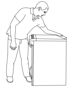
1. Slide range into final location, making sure rear leveling leg slides into anti-tip bracket. Leave a 1" (2.5 cm) gap between the back of the range and the back wall.
2. Place the outside of your foot against the bottom front of the warming drawer or baking drawer to keep the range from moving, and then grasp the back of the range, as shown.
3. Slowly attempt to tilt the range forward. If you encounter immediate resistance, the range foot is engaged in the anti-tip bracket. Go to Step 8.
4. If the rear of the range lifts more than 1/2" (1.3 cm) off the floor without resistance, stop tilting the range and lower it gently back to the floor. The range foot is not engaged in the anti-tip bracket. IMPORTANT: If there is a snapping or popping sound when lifting the range, the range may not be fully engaged in the bracket. Check to see if there are obstructions keeping the range from sliding to the wall or keeping the range foot from sliding into the bracket. Verify that the bracket is held securely in place by the mounting screws.
5. Slide the range forward, and verify that the anti-tip bracket is securely attached to the floor or wall.
6. Slide range back so the rear range foot is inserted into the slot of the anti-tip bracket.
7. Repeat steps 1 and 2 to ensure that the range foot is engaged in the anti-tip bracket. If the rear of the range lifts more than 1/2" (1.3 cm) off the floor without resistance, the anti-tip bracket may not be installed correctly. Do not operate the range without anti-tip bracket installed and engaged. Please reference the Quick Start Guide for contact information.
8. Move the range into its final location. Check that the range is level by placing a level on the oven bottom. See the “Level Range” section. IMPORTANT: If the range is moved to adjust the leveling legs, verify that the anti-tip bracket is engaged by repeating steps 1 to 8
Electronic Ignition System
Initial Lighting and Gas Flame Adjustments
- Cooktop and oven burners use electronic igniters in place of standing pilots.
- When the cooktop control knob is turned to the “ignite” position, the system creates a spark to light the burner. All cooktop burners will spark, but only the burner with the control knob turned to the “ignite” position will produce a flame. This sparking continues as long as the control knob is turned to the “ignite” position. When the oven control is turned to the desired setting, sparking occurs and ignites the gas.
Check Operation of Cooktop Burners
- Standard Surface Burners
- Push in and turn each control knob to the “ignite” position.
- The flame should light within 4 seconds. The first time a burner is lit, it may take longer than 4 seconds to light because of air in the gas line.
- If Burners Do Not Light Properly:
- Turn cooktop control knob to the “OFF” position.
- Check that the range is plugged into a grounded 3-prong outlet. Check that the circuit breaker has not tripped or the household fuse has not blown.
- Check that the gas shut-off valves are set to the open position.
- Check that burner caps are properly positioned on burner bases.
- Repeat start-up. If a burner does not light at this point, turn the control knobs to the “off” position and contact your dealer or authorized service company for assistance. Please reference the Quick Start Guide for contact information.
- If the cooktop “low” burner flame needs to be adjusted for any of the burners, see the “Adjust Flame Height” section.
Power Failure
- In case of prolonged power failure, the surface burners can be lit manually. Hold a lit match near a burner, and turn knob counterclockwise to LITE. After the burner lights, turn knob to desired setting
Check Operation of Oven Bake Burner
- Press BAKE.
- Press the Start pad. The oven burner should light within 8 seconds. The first time a burner is lit, it may take longer than 8 seconds to light because of air in the gas line.
- After 2 minutes, open the oven door and check that the oven is warm.
If Burner Does Not Light Properly:
- Press the Off pad.
- Check that the range is plugged into a grounded 3-prong outlet. Check that the circuit breaker has not tripped or the household fuse has not blown.
- Check that the gas shut-off valves are set to the open position.
Repeat steps 1 to 3. If the burner does not light at this point, press the off pad and contact your dealer or authorized service company for assistance. Please reference the Quick Start Guide for contact information.
If the bake burner flame needs to be adjusted, see the “Adjust Flame Height” section.
Refer to the Quick Start Guide and online Control Guide for proper operation of the oven controls.
Check Operation of Oven Broil Burner
- Close the oven door.
- Press BROIL.
- Press the Start pad. The oven burner should light within 8 seconds. The first time a burner is lit, it may take longer than 8 seconds to light because of air in the gas line.
- After 2 minutes, open the oven door and check that the oven is warm.
If Burner Does Not Light Properly:
- Press the Off pad.
- Check that the range is plugged into a grounded 3 prong outlet. Check that the circuit breaker has not tripped or the household fuse has not blown.
- Check that the gas shut-off valves are set to the open position.
Repeat steps 1 to 3. If the burner does not light at this point, press the Off pad and contact your dealer or authorized service company for assistance. Please reference the Quick Start Guide for contact information.
If the broil burner flame needs to be adjusted, see the “Adjust Flame Height” section. Refer to the Quick Start Guide and online Control Guide for proper operation of the oven controls.
Remove/Replace Drawer (On some models)
Remove all items from inside the baking drawer, warming drawer or premium storage drawer, and then allow the range to cool completely before attempting to remove the drawer.
To Remove:
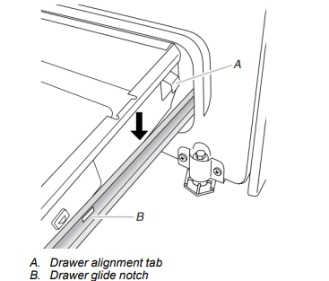
1. Open the drawer to its fully open position.
2. Using a flat-blade screwdriver, gently loosen the drawer from the glide alignment notch, and then lift up the drawer alignment tab from the glide.
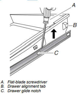
3. Repeat Step 2 on the other side. The drawer is no longer attached to the drawer glides. Using both hands, pick up the drawer to complete the removal.
To Replace:
1. Align the forward drawer notches with the notches in the drawer glides on both sides. Place the rear alignment tabs into the drawer glides on both sides.
2. Push the warming drawer or premium storage drawer in all the way.
3. Gently open and close the warming drawer or premium storage drawer to ensure it is seated properly on the glides on both sides.
Oven Door
For normal range use, it is not suggested to remove the oven door. However, if removal is necessary, make sure the oven is OFF and cool. Then, follow these instructions. The oven door is heavy.
To Remove:
1. Open oven door all the way.
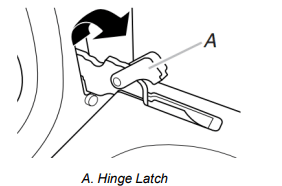
2. Pinch the hinge latch between two fingers and pull forward. Repeat on other side of oven door.
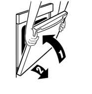
3. Close the oven door as far as it will shut.
4. Lift the oven door while holding both sides. Continue to push the oven door closed and pull it away from the oven door frame.
To Replace:
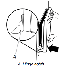
1. Insert both hanger arms into the door. Be sure that the hinge notches are engaged in the oven door frame.
2. Open the oven door. The door should be able to open all the way.
3. Move the hinge levers back to the “locked” position. Check that the door is free to open and close and is level while closed. If it is not, repeat the removal and installation procedures.
Complete Installation
- Check that all parts are now installed. If there is an extra part, go back through the steps to see which step was skipped.
- Check that you have all of your tools.
- Check that you have all of the range accessories, especially oven racks. These accessories may be in the range packaging.
- Dispose of/recycle all packaging materials.
- Check that the range is level. See the “Level Range” section.
- Use a mild solution of liquid household cleaner and warm water to remove waxy residue caused by shipping material. Dry thoroughly with a soft cloth. For more information, see the “Range Maintenance and Care” section.
- Read the Quick Start Guide.
- Turn on surface burners and oven. See the Quick Start Guide for specific instructions on range operation. NOTE: Odors and smoke are normal when the oven is used the first few times. If Range Does Not Operate, Check the Following:
- Household fuse is intact and tight, or circuit breaker has not tripped.
- Gas pressure regulator shut-off valve is in the open position.
- Range is plugged into a grounded 3 prong outlet.
- Electrical supply is connected.
- When the range has been on for 5 minutes, check for heat. If the range is cold, turn off the range and check that the gas supply line shut-off valve is open.
- If the gas supply line shut-off valve is closed, open it, and then repeat the 5 minute test as outlined above.
- If the gas supply line shut-off valve is open, close it, and contact a qualified technician. If You Need Assistance or Service: Please reference the Quick Start Guide for contact information.
GAS CONVERSIONS
Gas conversions from Natural gas to propane gas or from propane gas to Natural gas must be done by a qualified installer.
Explosion Hazard: Use a new CSA International approved gas supply line. Install a shut-off valve. Securely tighten all gas connections. If connected to propane, have a qualified person make sure gas pressure does not exceed 14ʺ (36 cm) water column. Examples of a qualified person include: licensed heating personnel, authorized gas company personnel, and authorized service personnel. Failure to do so can result in death, explosion, or fire.
WARNING: This conversion kit shall be installed by a qualified service agency in accordance with the manufacturer’s instructions and all applicable codes and requirements of the authority having jurisdiction. If the information in these instructions is not followed exactly, a fire, explosion or production of carbon monoxide may result causing property damage, personal injury or loss of life. The qualified service agency is responsible for the proper installation of this kit. The installation is not proper and complete until the operation of the converted appliance is checked as specified in the manufacturer’s instructions supplied with the kit.
Propane Gas Conversion
Tip Over Hazard:
A child or adult can tip the range and be killed. Install anti-tip bracket to floor or wall per installation instructions. Slide range back so rear range foot is engaged in the slot of the anti-tip bracket. Re-engage anti-tip bracket if range is moved. Do not operate range without anti-tip bracket installed and engaged. Failure to follow these instructions can result in death or serious burns to children and adults
1. Turn manual shutoff valve to the closed position.
2. Unplug range or disconnect power.
To Convert Gas Pressure Regulator (Natural gas to Propane)
1. Remove the premium storage drawer, warming drawer or baking drawer. See the “Remove/Replace Drawer”, “Storage Drawer” or “Warming Drawer or Premium Storage Drawer” section.
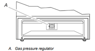
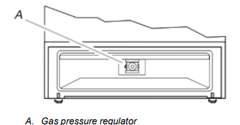
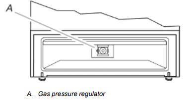
2. Locate gas pressure regulator at rear of the drawer compartment. NOTE: On models with a warming drawer or baking drawer, an access cover must be removed to access the gas pressure regulator.
3. Remove plastic cover from gas pressure regulator cap.
4. Turn gas pressure regulator cap counterclockwise with a 5/8" (1.6 cm) combination wrench to remove. NOTE: Do not remove the spring beneath the cap.
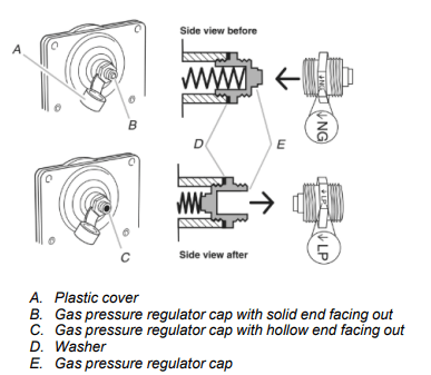
5. Turn over the gas pressure regulator cap and reinstall on regulator so that the hollow end faces out and the marking “↓LP” is facing the direction shown in the above drawing.
6. Replace plastic cover over gas pressure regulator cap
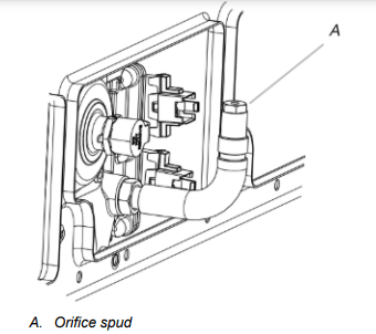
To Convert Surface Burners (Natural Gas to Propane Gas)
1. Remove burner cap.
2. Remove the burner base.
3. Apply masking tape to the end of a 9/32" (7 mm) nut driver to help hold the gas orifice spud in the nut driver while changing it. Press nut driver down onto the gas orifice spud and remove by turning it counterclockwise and lifting out. Set gas orifice spud aside.
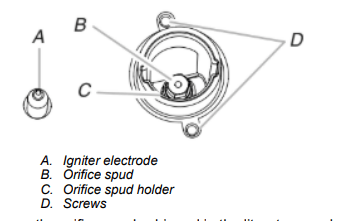
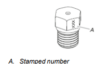
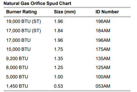
4. Remove the orifice spuds shipped in the literature package in the oven. Gas orifice spuds are stamped with a number and have a groove in the hex area. Replace the Natural gas orifice spud with the correct Propane gas orifice spud.
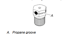
Refer to the following chart for correct Propane gas orifice spud ratings and to spud holder card for proper placement. Fully insert choke into bottom of x-large burner base. Choke should snap into place. NOTE: Use only for spreader bases marked “XL”.
Propane Gas Orifice Spud Chart for Surface Burner
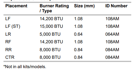
NOTE: Refer to the Model Number and Serial Number Plate located on the oven frame behind the top right side of the oven door for proper sizing of spuds for each burner location.
5. Place Natural gas orifice spuds in the orifice spud bag. IMPORTANT: Keep the Natural gas orifice spuds in case of reinstallation with Natural gas.
6. Replace the burner base.
7. Replace burner cap.
8. Repeat steps 1-7 for the remaining burners.
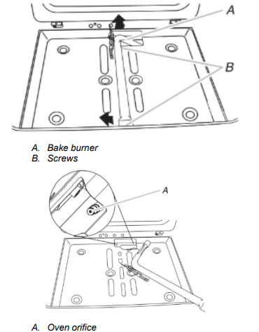
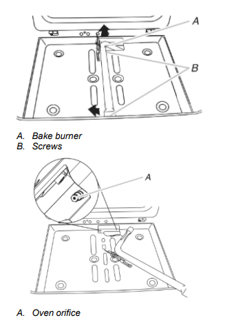
To Convert Oven Bake Burner (Natural Gas to Propane Gas)
1. Remove the oven racks and the oven door. See the “Oven Door” section.
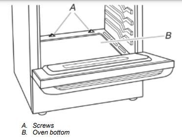
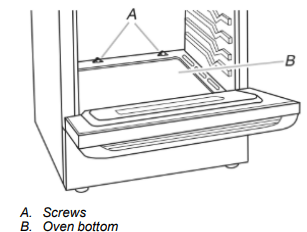
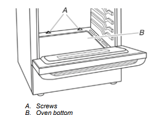
2. Remove two screws and washers at the rear of the oven bottom.
3. Lift the rear of the oven bottom up and back until the front of the panel is away from the front frame. Remove from oven and set it aside on a covered surface.
4. Remove two screws from the bake burner.
5. Slide the front of the bake burner to the side to remove tab from front of oven. Lift the back of the bake burner off the oven orifice and set the bake burner aside. Do not disconnect the wire.
6. Apply masking tape to the end of a 3/8" (9.5 mm) nut driver to help hold the gas orifice spud in the nut driver while changing it. Press nut driver down onto the gas orifice spud and remove by turning the Natural gas bake burner orifice spud counterclockwise to remove. The spud will be stamped with a “47.”
7. Replace the “47” spud with a “56” spud. Install the Propane gas bake burner orifice spud, turning it clockwise until snug. IMPORTANT: Do not overtighten.
8. Position the back of the bake burner over the oven orifice, and then align the holes for the screws.
9. Reattach the bake burner with two screws.
10. Position the front of the oven bottom panel toward the front frame, and then lower the rear of the oven bottom panel into the oven.
11. Reattach the oven bottom panel with two screws and two washers.
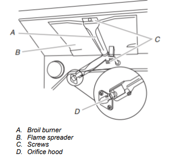
To Convert Oven Broil Burner (Natural Gas to Propane Gas)
1. Remove the one screw from the broil burner.
2. Remove the flame spreader.
3. Remove the broil burner from the broil burner orifice hood. NOTE: The broil burner will hang in the back of the oven while changing the orifice hood.
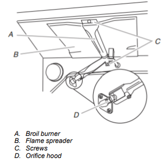
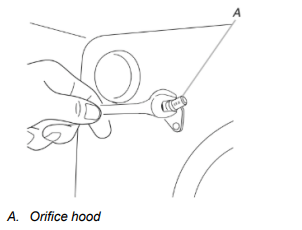
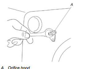
4. Apply masking tape to the end of a 3/8" (1 cm) nut driver to help hold the gas orifice spud in the nut driver while changing it. Press nut driver down onto the gas orifice spud and remove by turning the Natural gas broil burner orifice hood counterclockwise to remove. The hood will be stamped with a “155”.
5. Replace the “155” hood with a “100” hood. Install the Propane gas broiler burner orifice hood, turning it clockwise until snug. IMPORTANT: Do not overtighten.
6. Place the broil burner on the broil burner orifice hood. Insert the broil burner ceramic igniter in the hole in the rear of the oven.
7. Replace the flame spreader with all four tabs facing up and the notches toward the rear of the oven.
8. Position the broil burner against the top of the oven and attach it with one screw.
9. Replace premium storage drawer/storage drawer, warming drawer or baking drawer. See the “Remove/Replace Drawer” section.
10. Replace the oven door. See the “Oven Door” section.
11. Replace the oven racks.
Complete Installation (Natural Gas to Propane Gas)
- Refer to the “Make Gas Connection” section for properly connecting the range to the gas supply.
- Refer to the “Electronic Ignition System” section for proper burner ignition, operation.
- Refer to the “Adjust Flame Height” section for burner flame adjustments. IMPORTANT: You may have to adjust the low setting for each cooktop burner. Checking for proper cooktop flame is very important. The small inner cone should have a very distinct blue flame 1/4" to 1/2" (6.4 to 13 mm) long. The outer cone is not as distinct as the inner cone. Propane gas flames have a slightly yellow tip.
- Refer to “Complete Installation” in the “Installation Instructions” section of these instructions to complete this procedure. IMPORTANT: Make sure to save the orifices that have just been replaced in the conversion.
Natural Gas Conversion
1. Turn manual shutoff valve to the closed position.
2. Unplug range or disconnect power.
To Convert Gas Pressure Regulator (Propane Gas to Natural Gas)
1. Remove the premium storage drawer, warming drawer or baking drawer or premium storage drawer. See the Remove / Replace Drawer, Storage Drawer or Warming Drawer or Premium Storage Drawer section.
2. Locate gas pressure regulator at rear of the drawer compartment. NOTE: On models with a warming drawer or baking drawer, an access cover must be removed to access the gas pressure regulator.
3. Remove plastic cover from gas pressure regulator cap.
4. Turn gas pressure regulator cap counterclockwise with a 5/8" (1.6 cm) combination wrench to remove. NOTE: Do not remove the spring beneath the cap.
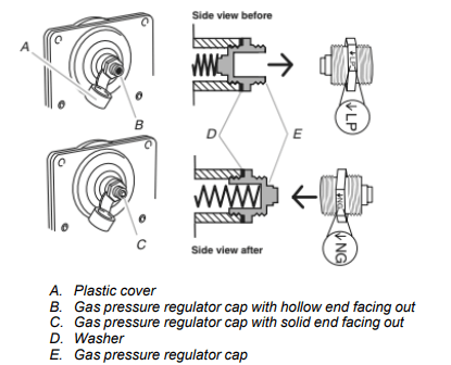
5. Turn over the gas pressure regulator cap and reinstall on regulator so that the solid end faces out and the marking “↓NG” is facing the direction shown in the above drawing.
6. Replace plastic cover over gas pressure regulator cap.
To Convert Surface Burners (Propane Gas to Natural Gas)
1. Remove burner cap.
2. Remove the burner base.
3. Apply masking tape to the end of a 9/32" (7 mm) nut driver to help hold the gas orifice spud in the nut driver while changing it. Press nut driver down onto the gas orifice spud and remove by turning it counterclockwise and lifting out. Set gas orifice spud aside.
4. Gas orifice spuds are stamped with a number on the side. Replace the Propane gas orifice spud with the correct Natural gas orifice spud.
Refer to the following chart for the correct Natural gas orifice spud placement.
5. Remove choke from x-large burner base.
NOTE: Refer to the model/serial/rating plate located on the oven frame behind the top right-hand side of the oven door for proper sizing of spuds for each burner location.
6. Place Propane gas orifice spuds in the orifice spud bag. IMPORTANT: Keep the Propane gas orifice spuds in case of reinstallation with Propane gas.
7. Replace the burner base.
8. Replace burner cap.
9. Repeat steps 1 through 7 for the remaining burners.
To Convert Oven Bake Burner (Propane Gas to Natural Gas)
1. Remove the oven racks and the oven door. See the “Oven Door” section
2. Remove two screws and washers at the rear of the oven bottom.
3. Lift the rear of the oven bottom up and back until the front of the panel is away from the front frame. Remove from oven and set it aside on a covered surface.
4. Remove two screws from the bake burner.
5. Slide the front of the bake burner to the side to remove tab from front of oven. Lift the back of the bake burner off the oven orifice, and set the bake burner aside. Do not disconnect the wire.
6. Apply masking tape to the end of a 3/8" (9.5 mm) nut driver to help hold the gas orifice spud in the nut driver while changing it. Press nut driver down onto the gas orifice spud and remove by turning the propane gas bake burner orifice spud counterclockwise to remove. The spud will be stamped with a “56”.
7. Replace the “56” spud with a “47” spud. Install the Natural gas bake burner orifice spud, turning it clockwise until snug. IMPORTANT: Do not overtighten.

8. Position the back of the bake burner over the oven orifice, and then align the holes for the screws.
9. Reattach the bake burner with two screws.
10. Position the front of the oven bottom panel toward the front frame, and then lower the rear of the oven bottom panel into the oven.
11. Reattach the oven bottom panel with two screws and two washers.
To Convert Oven Broil Burner (Propane Gas to Natural Gas)(On some models)
1. Remove 1 screw from the broil burner.
2. Remove the flame spreader.
3. Remove the broil burner from the broil burner orifice hood. NOTE: The broil burner will hang in the back of the oven while changing the orifice hood.
4. Apply masking tape to the end of a 3/8" (1 cm) nut driver to help hold the gas orifice spud in the nut driver while changing it. Press nut driver down onto the gas orifice spud and remove by turning the Propane gas broil burner orifice hood counterclockwise to remove. The hood will be stamped with a “100”.
5. Replace the “100” hood with a “155” hood. Install the Natural gas broiler burner orifice hood, turning it clockwise until snug. IMPORTANT: Do not overtighten.
6. Place the broil burner on the broil burner orifice hood. Insert the broil burner ceramic igniter in the hole in the rear of the oven.
7. Replace the flame spreader with all 4 tabs facing up and the notches toward the rear of the oven.
8. Position the broil burner against the top of the oven and attach it with 1 screw.
9. Replace the storage drawer. See the “Remove/Replace Drawer” section.
10. Replace the oven door. See the “Oven Door” section.
11. Replace the oven racks.
Complete Installation (Propane Gas to Natural Gas)
- Refer to the “Make Gas Connection” section for proper connection of the range to the gas supply.
- Refer to the “Electronic Ignition System” section for proper burner ignition and operation.
- Refer to the “Adjust Flame Height” section for burner flame adjustments. IMPORTANT: You may have to adjust the low setting for each cooktop burner. Checking for proper cooktop, bake and broil burner flame is very important. Natural gas flames do not have yellow tips.
- Refer to “Complete Installation” in the “Installation Instructions” section of these instructions to complete this procedure. IMPORTANT: Make sure to save the orifices that have just been replaced in the conversion
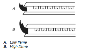
Adjust Flame Height Adjust Surface Burner Flame
Adjust the height of top burner flames. The cooktop “low” burner flame should be a steady blue flame approximately 1/4" (6.3 mm) high. Propane gas flames have a slightly yellow tip.
To Adjust Standard Burner: The flame can be adjusted using the adjustment screw in the center of the valve stem. The valve stem is located directly underneath the control knob.
If the “Low” Flame Needs to Be Adjusted:
- Light 1 burner and turn to lowest setting.
- Remove the control knob. Hold the knob stem with a pair of pliers. Use a small flatblade screwdriver to turn the screw located in the center of the control knob stem until the flame is the proper size. Turning the screw clockwise will increase the flame size and counterclockwise will decrease the flame size.
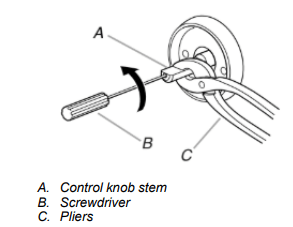
- Replace the control knob.
- Test the flame by turning the control from the low position to the high position, checking the flame at each setting.
- Repeat the previous steps for each burner.
To Adjust Double Burner (On Some Models):
1. Light burner and turn to lowest setting where both inner and outer burners are lit.
2. Remove the control knob.
3. Insert a 1/8" (3 mm) flat-blade screwdriver into the adjustment locations shown in the following illustration and engage the slotted screw. Turn the screw until the flame is the proper size. Turning the screw clockwise will increase the flame size and counterclockwise will decrease the flame size.
4. Replace the control knob.
5. Test the flame by turning the control from the low position to the high position, checking the flame at each setting.
Check Operation of Oven Bake Burner: Refer to the Quick Start Guide and online Control Guide for proper operation of the oven controls.
Adjust Oven Bake Burner Flame (If Needed)
1. Remove the premium storage drawer, warming drawer or baking drawer or storage drawer(see the “Remove/Replace Drawer” section).
2. Locate gas pressure regulator at rear of the drawer compartment.
IMPORTANT: Do not remove the gas pressure regulator.
3. Check the oven bake burner for proper flame.
- Remove the oven racks.
- To remove the oven bottom: Remove 2 screws at the rear of the oven bottom. Lift the rear of the oven bottom up and back until the front of the panel is away from the front frame. Remove from oven and place on a covered surface.
- Press BAKE.
- Press the Start pad. The oven bake burner should light within 8 seconds. Under certain conditions, it may take the burner up to 50 to 60 seconds to light. Electronic igniters are used to light the bake and broil burners. This flame should have a 1/2" (1.3 cm) long inner cone of bluish-green with an outer mantle of dark blue and should be clean and soft in character. No yellow tips, blowing, or lifting of flame should occur.
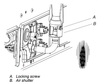
4. If the oven bake flame needs to be adjusted, locate the air shutter near the center rear of the drawer cavity behind the access panel. Loosen the locking screw and rotate the air shutter until the proper flame appears. Tighten locking screw.
5. Push the Off pad when finished.
6. Reinstall the oven bottom and the storage drawer (see the “Remove/Replace Drawer” section).
Adjust Oven Broil Burner Flame (If Needed)
Press BROIL, and then press the start pad. Look through the oven window to check broil burner for proper flame. This flame should have a 1/2" (1.3 cm) long inner cone of bluish-green with an outer mantle of dark blue and should be clean and soft in character. No yellow tips, blowing, or lifting of flame should be present.
If Flame Needs to be Adjusted:
1. Press the Off pad. Let the oven cool.
2. Loosen the lock screw on the air shutter located at the rear of the broil burner.
3. Adjust the air shutter as needed.
4. Tighten lock screw.
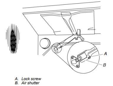
5. Close the oven door. Press BROIL, and then press the Start pad. Look through the oven window to check broil burner for proper flame. If flame needs to be adjusted, repeat steps 1 to 5.
Moving the Range
Tip Over Hazard: A child or adult can tip the range and be killed. Install anti-tip bracket to floor or wall per installation instructions. Slide range back so rear range foot is engaged in the slot of the anti-tip bracket. Re-engage anti-tip bracket if range is moved. Do not operate range without anti-tip bracket installed and engaged. Failure to follow these instructions can result in death or serious burns to children and adults.
When moving range, slide range onto cardboard or hardboard to avoid damaging the floor covering.
If removing the range is necessary for cleaning or maintenance:
For power supply cord-connected ranges:
1. Slide range forward.
2. Turn manual shutoff valve to the closed position.
3. Unplug the power supply cord.
4. Disconnect the gas supply tubing.
5. Complete cleaning or maintenance.
6. Reconnect the gas supply tubing.
7. Open the manual shutoff valve in the gas supply line.
8. Plug in power supply cord.
9. Slide range back so rear range foot is under anti-tip bracket.
10. Refer to the “Verify Anti-Tip Bracket Is Installed and Engaged” section to verify engagement.
11. Check that range is level