Owner 's Manual for Gas Range
RANGE MAINTENANCE AND CARE
General Cleaning
IMPORTANT: Before cleaning, make sure all controls are OFF and the oven and cooktop are cool. Always follow label instructions on cleaning products. Soap, water, and a soft cloth or sponge are suggested first, unless otherwise noted.
EXTERIOR PORCELAIN ENAMEL SURFACES (on some models)
Food spills containing acids, such as vinegar and tomato, should be cleaned as soon as the entire range is cool. These spills may affect the finish.
Cleaning Method:
■ Glass cleaner, mild liquid cleaner, or nonabrasive scrubbing pad: Gently clean around the model/serial/rating plate because scrubbing may remove numbers.
■ Affresh®† Kitchen and Appliance Cleaner Part Number W10355010 (not included): See the Quick Start Guide for ordering information.
STAINLESS STEEL (on some models)
NOTE: To avoid damage to stainless steel surfaces, do not use soap-filled scouring pads, abrasive cleaners, Cooktop Cleaner, steel-wool pads, gritty washcloths, or abrasive paper towels. Damage may occur to stainless steel surfaces, even with one-time or limited use.
Cleaning Method:
■ Rub in direction of grain to avoid damaging.
■ Affresh® Stainless Steel Cleaner Part Number W10355016 (not included): See the Quick Start Guide for ordering information.
METALLIC PAINT (on some models)
Do not use abrasive cleaners, cleaners with bleach, rust removers, ammonia, or sodium hydroxide (lye) because paint surface may stain.
PORCELAIN-COATED GRATES AND CAPS
Food spills containing acids, such as vinegar and tomato, should be cleaned as soon as the cooktop, grates and caps are cool. These spills may affect the finish.
To avoid chipping, do not bang grates, and caps against each other or hard surfaces such as cast iron cookware. Do not reassemble caps on burners while wet.
Do not clean in the Self-Cleaning cycle.
Cleaning Method:
■ Nonabrasive plastic scrubbing pad and mildly abrasive cleanser: Clean as soon as cooktop, grates, and caps are cool.
■ Dishwasher (grates only, not caps): Use the most-aggressive cycle. Cooked-on soils should be soaked or scrubbed before going into a dishwasher. Although the burner grates are durable, they may lose their shine and/or discolor when washed in a dishwasher.
■ Gas Grate and Drip Pan Cleaner Part Number 31617 (not included): See the Quick Start Guide for ordering information.
SURFACE BURNERS
Food spills containing acids, such as vinegar and tomato, should be cleaned as soon as the cooktop, grates, and caps are cool. These spills may affect the finish.
To avoid chipping, do not bang grates and caps against each other or hard surfaces such as cast iron cookware.
Do not reassemble caps on burners while wet.
Do not clean in the Self-Cleaning cycle.
Do not clean in dishwasher.
Cleaning Method:
■ Nonabrasive plastic scrubbing pad and mildly abrasive cleanser: Clean as soon as cooktop, grates, burners, and caps are cool.
■ Gas Grate and Drip Pan Cleaner (not included).
COOKTOP CONTROLS
To avoid damage to the cooktop controls, do not use steel wool, abrasive cleansers, or oven cleaner.
To avoid damage, do not soak knobs. When replacing knobs, make sure knobs are in the Off position.
On some models, do not remove seals under knobs.
Cleaning Method:
■ Soap and water: Pull knobs straight away from control panel to remove
CONTROL PANEL AND OVEN DOOR EXTERIOR
To avoid damage to the control panel, do not use abrasive cleaners, steel-wool pads, gritty washcloths, or abrasive paper towels.
Cleaning Method:
■ Glass cleaner and soft cloth or sponge: Apply glass cleaner to soft cloth or sponge, not directly on panel.
■ Affresh® Kitchen and Appliance Cleaner Part Number W10355010 (not included): See the Quick Start Guide for ordering information.
OVEN RACKS
Cleaning Method:
■ Steel-wool pad
■ For racks that have discolored and are harder to slide, a light coating of vegetable oil applied to the rack guides will help them slide.
■ Dishwasher (steam rack water reservoir only, not racks): Although the water reservoir is durable, it may lose its shine and/or discolor when washed in a dishwasher.
STORAGE/WARMING DRAWER (on some models)
Check that storage/warming drawer is cool and empty before cleaning.
Cleaning Method:
■ Mild detergent
OVEN CAVITY
Do not use oven cleaners.
Food spills should be cleaned when oven cools. At high temperatures, foods react with porcelain. Staining, etching, pitting, or faint white spots can result.
Cleaning Method:
■ Self-Cleaning cycle: See the “Self-Cleaning Cycle” or “Clean Cycle” section first.
Self-Cleaning Cycle
WARNING Burn Hazard Do not touch the oven during the Self-Cleaning cycle. Keep children away from the oven during Self-Cleaning cycle. Failure to follow these instructions can result in burns.
IMPORTANT: The health of some birds is extremely sensitive to the fumes given off during the Self-Cleaning cycle. Exposure to the fumes may result in death to certain birds. Always move birds to another closed and well-ventilated room.
Keep the kitchen well-ventilated during the Self-Cleaning cycle to help get rid of heat, odors, and smoke.
Do not block the oven vent(s) during the Self-Cleaning cycle. Air must be able to move freely. Depending on your model, see the Oven Vent” or “Oven Vents” section in the Quick Start Guide.
Do not clean, rub, damage, or move the oven door gasket.
Prepare Range
■ Remove the broiler pan, grid, cookware and bakeware, all cooking utensils, oven racks, and aluminum foil and, on some models, the temperature probe from the oven.
■ Use a damp cloth to clean inside door edge and the 11/2" (3.8 cm) area around the inside oven cavity frame, being certain not to move or bend the gasket.
■ Wipe out any loose soil to reduce smoke and avoid damage. At high temperatures, foods react with porcelain. Staining, etching, pitting, or faint white spots can result. This will not affect cooking performance.
■ Remove plastic items from the cooktop because they may melt.
■ Remove all items from the storage drawer
How the Cycle Works
IMPORTANT: The heating and cooling of porcelain on steel in the oven may result in discoloring, loss of gloss, hairline cracks and popping sounds.
Before self-cleaning, make sure the door is completely closed or the door will not lock and the Self-Cleaning cycle will not begin.
The Self-Cleaning cycle uses very high temperatures, burning soil to a powdery ash.
Once the oven has completely cooled, remove ash with a damp cloth. To avoid breaking the glass, do not apply a cool, damp cloth to the inner door glass before it has completely cooled.
To stop the Self-Cleaning cycle at any time, press the Cancel keypad. If the temperature is too high, the oven door will remain locked and “cool” and “(lock symbol) ” will be displayed. The cooling fan may continue to run.
When “locked” shows in the display, the door of the oven cannot be opened. To avoid damage to the door, do not force the door open when “locked” is displayed.
Once the cleaning temperature has been reached, the electronic control requires a 12 hour delay before another Self-Cleaning cycle can be started.
The oven light will not function during the Self-Cleaning cycle.
Electronic Oven Control with Adjustable Clean Time (on some models)
The Self-Cleaning cycle is time adjustable between 2 hours 30 minutes and 4 hours 30 minutes in 15 or 30 minute increments. Suggested clean times are 2 hours 30 minutes for light soil and 4 hours 30 minutes for heavy soil. The last 30 minutes of the cycle is for cooldown.
To Self-Clean:
1. Press SELF CLEAN.
2. Press the Temp/Time “+” or “-” keypad to enter the desired Self-Cleaning cycle time.
3. Press START. The oven door will automatically lock. The DOOR LOCKED and CLEAN indicator lights will be displayed. The time remaining will also be displayed.
4. When the self-clean cycle is complete and the oven cools, the DOOR LOCKED and CLEAN indicator lights will turn off.
5. When the oven is completely cooled, remove ash with a damp cloth. To exit the Self-Cleaning cycle before completed, press CANCEL. The door will unlock once the oven cools.
INSTALLATION INSTRUCTIONS REQUIREMENTS
Tools and Parts
Gather the required tools and parts before starting installation. Read and follow the instructions provided with any tools listed here.
Tools Needed
■ Tape measure
■ Flat-blade screwdriver
■ Phillips screwdriver
■ 1/8" flat-blade screwdriver
■ Level
■ Hand or electric drill
■ Hammer
■ Wrench or pliers
■ Pipe wrench
■ 15/16" combination wrench
■ 1/4" drive ratchet
■ 3/8" nut driver
■ 1/8" drill bit (for wood floors)
■ Marker or pencil
■ Pipe-joint compound resistant to Propane gas
■ Noncorrosive leak-detection solution
■ 3/16" carbide-tipped masonry drill bit (for concrete/ceramic floors) (For Slide-in/Front Control Ranges)
For Propane/Natural Gas Conversions
■ 3/8" combination wrench
■ 1/2" combination wrench
■ 5/8" combination wrench
■ 9/32" nut driver
■ Quadrex®† or Phillips screwdriver
■ Masking tape
■ 3/8" nut driver (For Slide-in/Front Control Ranges)
Parts Supplied
Check that all parts are included.
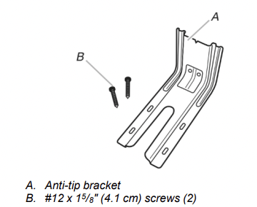
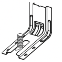
Anti-tip bracket must be securely mounted to floor or wall. Thickness of flooring may require longer screws to anchor bracket to floor
Parts needed
Check local codes and consult gas supplier. Check existing gas supply and electrical supply. See “Electrical Requirements” and “Gas Supply Requirements” sections.
NOTE: Be sure to purchase only whirlpool factory-certified parts and accessories for your appliance. Your installation may require additional parts. To order, refer to the contact information referenced in your Quick Start Guide.
Location Requirements
IMPORTANT: Observe all governing codes and ordinances. Do not obstruct flow of combustion and ventilation air.
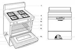
■ It is the installer’s responsibility to comply with installation clearances specified on the model/serial/rating plate. The model/serial/rating plate is located behind the oven door on the top right/left-hand side of the oven frame.
■ The range should be located for convenient use in the kitchen.
■ Recessed installations must provide complete enclosure of the sides and rear of the range.
■ All openings in the wall or floor where range is to be installed must be sealed.
■ Cabinet opening dimensions that are shown must be used. Given dimensions are minimum clearances.
■ The anti-tip bracket must be installed. To install the anti-tip bracket shipped with the range, see “Install Anti-Tip Bracket” section.
■ Grounded electrical supply is required. See “Electrical Requirements” section.
■ Proper gas supply connection must be available. See “Gas Supply Requirements” section.
■ Contact a qualified floor covering installer to check that the floor covering can withstand at least 200°F (93°C).
■ Use an insulated pad or 1/4" (6.4 mm) plywood under range if installing range over carpeting.
IMPORTANT: To avoid damage to your cabinets, check with your builder or cabinet supplier to make sure that the materials used will not discolor, delaminate or sustain other damage. This oven has been designed in accordance with the requirements of UL and CSA International and complies with the maximum allowable wood cabinet temperatures of 194°F (90°C).
Cabinet Dimensions
Cabinet opening dimensions shown are for 25" (64.0 cm) countertop depth, 24" (61.0 cm) base cabinet depth and 36" (91.4 cm) countertop height.
IMPORTANT: If installing a range hood or microwave hood combination above the cooking surface, follow the range hood or microwave hood combination installation instructions for dimensional clearances above the cooktop surface.
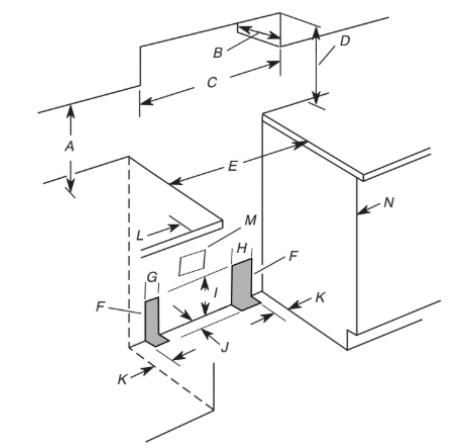
A. 18" (45.7 cm) upper side cabinet to countertop
B. 13" (33 cm) maximum upper cabinet depth
C. 30" (76.2 cm) minimum opening width
D. For minimum clearance to top of cooktop, see NOTE*.
E. 30" (76.2 cm) minimum opening width
F. The shaded areas are recommended for installation of rigid gas pipe.
G. 41⁄2" (11.4 cm)
H. 8" (20.3 cm)
I. 17" (43.2 cm)
J. 2" (5.1 cm)
K. 41⁄2" (11.4 cm)
L. 3" (7.6 cm) min. clearance from both sides of range to side wall or other combustible material.
M. Grounded outlet
N. Cabinet door or hinges should not extend into the cutout.
NOTE: 24" (61.0 cm) minimum when bottom of wood or metal cabinet is shielded by not less than 1/4" (6.4 mm) flame retardant millboard covered with not less than No. 28 MSG sheet steel, 0.015" (0.4 mm) stainless steel, 0.024" (0.6 mm) aluminum or 0.020" (0.5 mm) copper. 30" (76.2 cm) minimum clearance between the top of the cooking platform and the bottom of an uncovered wood or metal cabinet.
Install Anti-Tip Bracket
WARNING Tip Over Hazard
A child or adult can tip the range and be killed.
Install anti-tip bracket to floor or wall per installation instructions.
Slide range back so rear range foot is engaged in the slot of the anti-tip bracket.
Re-engage anti-tip bracket if range is moved.
Do not operate range without anti-tip bracket installed and engaged.
Failure to follow these instructions can result in death or serious burns to children and adults.
1. Remove the anti-tip bracket from where it is taped inside the storage drawer, warming drawer, or premium storage drawer
2. Determine which mounting method to use: floor or wall. If you have a stone or masonry floor, you can use the wall mounting method. If you are installing the range in a mobile home, you must secure the range to the floor.
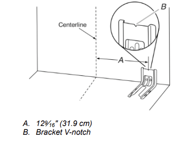
3. Determine and mark centerline of the cutout space. The mounting can be installed on either the left side or right side of the cutout. Position mounting bracket against the wall in the cutout so that the V-notch of the bracket is 129⁄16" (31.9 cm) from centerline as shown.
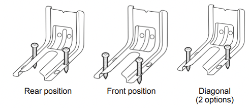
4. Drill two 1/8" (3 mm) holes that correspond to the bracket holes of the determined mounting method. See the following illustrations
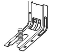
Floor Mounting
Wall Mounting
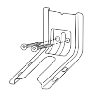
5. Using the Phillips screwdriver, mount anti-tip bracket to the wall or floor with the two #12 x 15/8" (4.1 cm) screws provided, mount anti-tip bracket to the wall or floor.
6. Move range close enough to opening to allow for final gas and electrical connections. Remove shipping base, cardboard or hardboard from under range.
7. Move range into its final location, making sure rear leveling leg slides into anti-tip bracket.
8. Move range forward onto shipping base, cardboard or hardboard to continue installing the range using the following installation instructions.
Make Gas Connection
WARNING Explosion Hazard
Use a new CSA International approved gas supply line. Install a shut-off valve.
Securely tighten all gas connections.
If connected to propane, have a qualified person make sure gas pressure does not exceed 14ʺ (36 cm) water column.
Examples of a qualified person include: licensed heating personnel, authorized gas company personnel, and authorized service personnel.
Failure to do so can result in death, explosion, or fire.
Typical rigid pipe connection
A combination of pipe fittings must be used to connect the range to the existing gas line. Your connections may be different, according to the supply line type, size and location.
1. Apply pipe-joint compound made for use with Propane gas to all pipe thread connections.
2. Using a pipe wrench to tighten, connect the gas supply to the range.
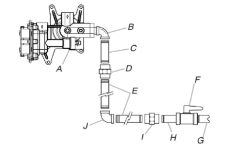
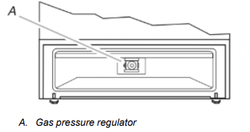
A. Gas pressure regulator
B. 90° elbow (must have 1/3" [1.2 cm] male pipe thread)
C. Nipple
D. Union
E. Black iron pipe
F. Manual gas shutoff valve
G. 1/2" (1.3 cm) or 3/4" (1.9 cm) gas pipe
H. Nipple
I. Union
J. 90° elbow
Typical flexible connection
1. Apply pipe-joint compound made for use with propane gas to the smaller thread ends of the flexible connector adapters (see B and G in the following illustration).
2. Attach one adapter to the gas pressure regulator and the other adapter to the gas shut-off valve. Tighten both adapters.
3. Use a 15/16" (23.8 mm) combination wrench and channel lock pliers to attach the flexible connector to the adapters. Check that connector is not kinked.
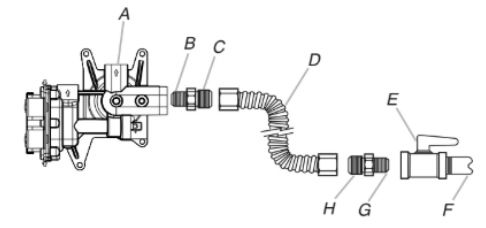
A. Gas pressure regulator
B. Use pipe-joint compound.
C. Adapter (must have 1/3" [12.7 mm] male pipe thread)
D. Flexible connector
E. Manual gas shutoff valve
F. 1/2" (12.7 mm) or 3/4" (19.1 mm) gas pipe
G. Use pipe-joint compound.
H. Adapter
Complete Connection
1. Check that the gas pressure regulator shutoff valve is in the “on” position.
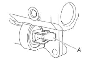
A. Gas pressure regulator shut-off valve shown in the “on” position
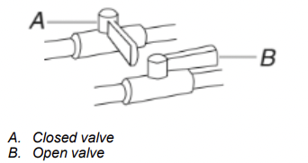
2. Open the manual shutoff valve in the gas supply line. The valve is open when the handle is parallel to the gas pipe.
3. Test all connections by brushing on an approved noncorrosive leak-detection solution. If bubbles appear, a leak is indicated. Correct any leak found.
4. Remove cooktop burner caps and bases from package containing parts. Place the burner bases as indicated by the following illustration for your model:
For Models WFG525S0J and WFG535S0J:
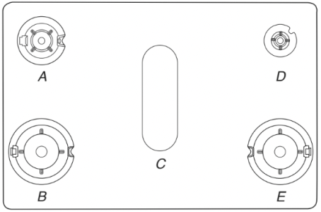
A. Medium (Semi Rapid)
B. Large (Ultra Rapid)
C. Oval
D. Small (Auxiliary)
E. Large (Ultra Rapid)
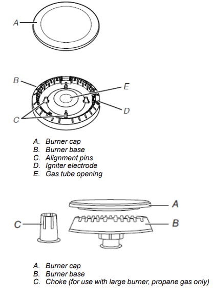
5. Burner caps should be level when properly positioned. If burner caps are not properly positioned, surface burners will not light. Place burner grates over burners and caps.
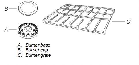
6. Place the burner caps on the appropriate burner bases.
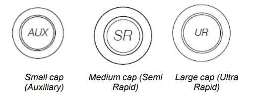
IMPORTANT: The bottom of the small and medium caps are different. Do not put the wrong size burner cap on the burner base. Each round burner cap is marked with an AUX, SR, UR, or ST to match with a letter on the burner base.
WARNING Electrical Shock Hazard
Plug into a grounded 3 prong outlet.
Do not remove ground prong.
Do not use an adapter.
Do not use an extension cord.
Failure to follow these instructions can result in death, fire, or electrical shock.
7. Plug into a grounded 3-prong outlet.
8. Slide range into final location, making sure the rear leveling leg slides into the slot of the anti-tip bracket.
Verify Anti-Tip Bracket Is Installed and Engaged
On Ranges Equipped with a Storage Drawer:
1. Remove the storage drawer. See the “Storage Drawer” section.
2. Use a flashlight to look underneath the bottom of the range.
3. Visually check that the rear range foot is inserted into the slot of the anti-tip bracket.
On Ranges Equipped with a Warming Drawer or Premium Storage Drawer:
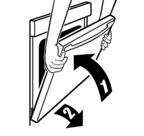
1. Place the outside of your foot against the bottom front of the warming drawer or premium storage drawer, and grasp the lower right or left side of the control panel as shown.
NOTE: If your countertop is mounted with a backsplash, it may be necessary to grasp the range higher than is shown in the illustration.
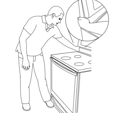
2. Slowly attempt to tilt the range forward. If you encounter immediate resistance, the range foot is engaged in the anti-tip bracket.
3. If the rear of the range lifts more than 1/2" (1.3 cm) off the floor without resistance, stop tilting the range and lower it gently back to the floor. The range foot is not engaged in the anti-tip bracket.
IMPORTANT: If there is a snapping or popping sound when lifting the range, the range may not be fully engaged in the bracket. Check to see if there are obstructions keeping the range from sliding to the wall or keeping the range foot from sliding into the bracket. Verify that the bracket is held securely in place by the mounting screws.
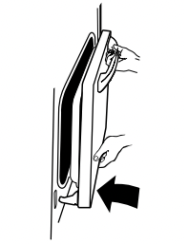
4. Slide the range forward, and verify that the anti-tip bracket is securely attached to the floor or wall.
5. Slide range back so the rear range foot is inserted into the slot of the anti-tip bracket.
IMPORTANT: If the back of the range is more than 2" (5.1 cm) from the mounting wall, the rear range foot may not engage the bracket. Slide the range forward and determine if there is an obstruction between the range and the mounting wall. Changes to the gas supply must be performed by a qualified service technician. If you need assistance or service, refer to the Quick Start Guide for contact information.
6. Repeat steps 1 and 2 to ensure that the range foot is engaged in the anti-tip bracket. If the rear of the range lifts more than 1/2" (1.3 cm) off the floor without resistance, the anti-tip bracket may not be installed correctly. Do not operate the range without anti-tip bracket installed and engaged. If you need assistance or service, refer to the Quick Start Guide for contact information.
Level Range
Determine if you have AquaLift® Technology or Steam Clean by referring to the “Range Maintenance and Care” section.
For Ranges with AquaLift® Technology or Steam Clean:
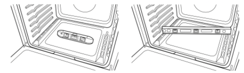
1. Place level on the oven bottom as indicated in one of the two figures below depending on the size of the level. Check with the level side to side and front to back.
2. If range is not level, pull range forward until rear leveling leg is removed from the anti-tip bracket.
3. Follow the directions in Style 1 or Style 2, depending on the style of drawer supplied with the range.
For Ranges without AquaLift® Technology or Steam Clean:
1. Place a standard flat rack in oven.
2. Place level on the rack and check levelness of the range, first side to side; then front to back.
3. If range is not level, pull range forward until rear leveling leg is removed from the anti-tip bracket.
4. Follow the directions in Style 1 or Style 2, depending on the style of drawer supplied with the range.
Style 1: Ranges Equipped with a Storage Drawer:
Use a 1/4" (6.4 mm) drive ratchet, wrench or pliers to adjust leveling legs up or down until the range is level. Push range back into position. Check that rear leveling leg is engaged in the anti-tip bracket.
Style 2: Ranges Equipped with a Warming Drawer or Premium Storage Drawer:
Use a wrench or pliers to adjust leveling legs up or down until the range is level. Push range back into position. Check that rear leveling leg is engaged in the anti-tip bracket.
NOTE: Range must be level for satisfactory baking performance and best cleaning results using AquaLift® Technology and Steam Clean functions.
Electronic Ignition System
Initial Lighting and Gas Flame Adjustments
Cooktop and oven burners use electronic igniters in place of standing pilots. When the cooktop control knob is turned to the "LITE” position, the system creates a spark to light the burner. This sparking continues, as long as the control knob is turned to "LITE.”
When the oven control is turned to the desired setting, sparking occurs and ignites the gas.
Check Operation of Cooktop Burners
Standard Surface Burners
Push in and turn each control knob to the “LITE” position.
The flame should light within 4 seconds. The first time a burner is lit, it may take longer than 4 seconds to light because of air in the gas line.
If Burners Do Not Light Properly:
- Turn cooktop control knob to the “OFF” position.
- Check that the range is plugged in. Check that the circuit breaker has not tripped or the household fuse has not blown.
- Check that the gas shutoff valves are set to the “open” position.
- Check that burner caps are properly positioned on burner bases.
Repeat start-up. If a burner does not light at this point, turn the control knobs to the “OFF” position and contact your dealer or authorized service company for assistance.
Power Failure
In case of prolonged power failure, the surface burners can be lit manually. Hold a lit match near a burner, and turn knob counterclockwise to LITE. After the burner lights, turn knob to desired setting.
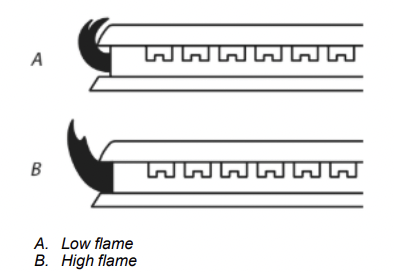
Adjust Flame Height
Adjust the height of top burner flames. The cooktop “low” burner flame should be a steady blue flame approximately 1/4" (6.4 mm) high.
To adjust standard burner:
The flame can be adjusted using the adjustment screw in the center of the valve stem. The valve stem is located directly underneath the control knob.
If the “low” flame needs to be adjusted:

1. Light 1 burner and turn to lowest setting.
2. Remove the control knob. Hold the knob stem with a pair of pliers. Use a small flat blade screwdriver to turn the screw located in the center of the control knob stem until the flame is the proper size.
3. Replace the control knob.
4. Test the flame by turning the control from “LO” to “HI,” checking the flame at each setting.
5. Repeat the previous steps for each burner.
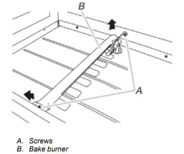
Check Operation of Oven Bake Burner
1. Remove the oven rack.
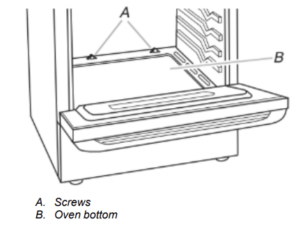
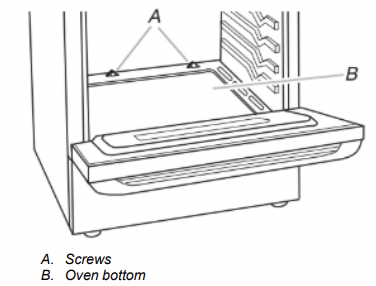
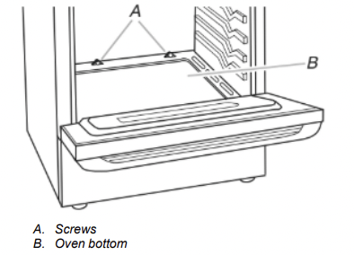
2. To remove the oven bottom: Remove 2 screws at the rear of the oven bottom. Lift the rear of the oven bottom up and back until the front of the panel is away from the front frame. Remove from oven and place on a covered surface.
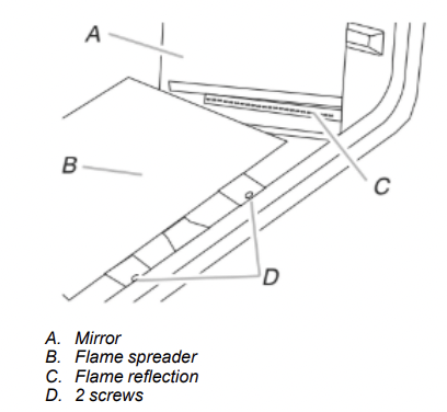
3. You can check the burner flame by removing the flame spreader or by using a mirror.
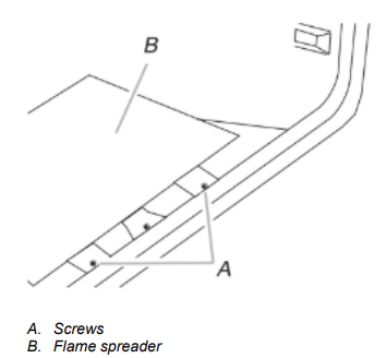
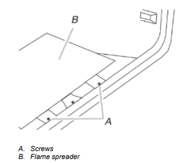
Remove flame spreader:
Remove 2 screws from the front tabs of the flame spreader. Lift front of the flame spreader and pull forward to remove tabs from rear of oven.
Using a mirror:
Insert a mirror to one side of the burner. Look into the mirror to check flame.
4. Push the BAKE pad.
5. Press the START pad.
The oven bake burner should light within 8 seconds. Under certain conditions, it may take the burner up to 50 to 60 seconds to light.
Electronic igniters are used to light the bake and broil burners.
Refer to the Quick Start Guide and online Control Guide for proper operation of the oven controls.
Adjust Oven Bake Burner Flame (if needed)
1. On models with a warming drawer, remove access cover plate (1 screw) located at the back of the warming drawer compartment.
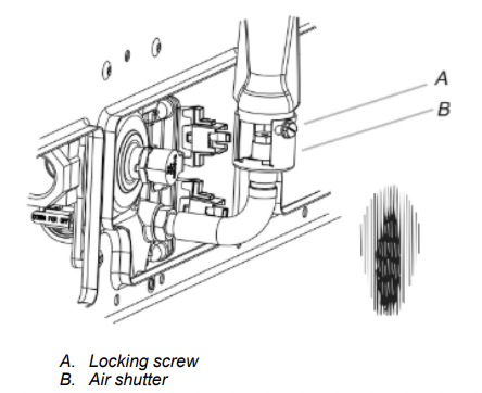
2. Check the oven bake burner for proper flame. This flame should have a 1/2" (1.3 cm) long inner cone of bluish-green, with an outer mantle of dark blue, and should be clean and soft in character. No yellow tips, blowing or lifting of flame should occur.
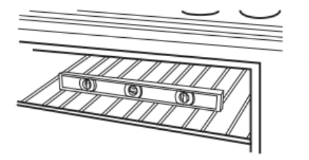
3. If the oven bake flame needs to be adjusted, locate the air shutter near the center rear of the range. Loosen the locking screw and rotate the air shutter until the proper flame appears. Tighten locking screw.
4. Push CANCEL/OFF when finished.
5. Reinstall flame spreader and oven bake burner cover.
Check Operation of Oven Broil Burner
- Close the oven door.
- Press the BROIL pad.
- Press the START pad.
The oven burner should light within 8 seconds. Under certain conditions, it may take the burner up to 50 to 60 seconds to light.
Refer to the Quick Start Guide and online Control Guide for proper operation of the oven controls.
Adjust Oven Broil Burner Flame (if needed)
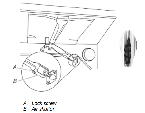
Look through oven window to check broil burner for proper flame.
This flame should have a 1/2" (1.3 cm) long inner cone of bluishgreen, with an outer mantle of dark blue, and should be clean and soft in character. No yellow tips, blowing or lifting of flame should be present.
If flame needs to be adjusted:
- Loosen the lock screw on the air shutter located at the rear of the broil burner.
- Adjust the air shutter as needed.
- Tighten lock screw.
4. Press CANCEL/OFF when finished.
Warming Drawer or Premium Storage Drawer (on some models)
Remove all items from inside the baking drawer, warming drawer or premium storage drawer, and then allow the range to cool completely before attempting to remove the drawer.
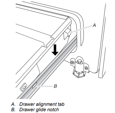
To Remove:
1. Open the drawer to its fully open position.
2. Using a flat-blade screwdriver, gently loosen the drawer from the glide alignment notch, and then lift up the drawer alignment tab from the glide.
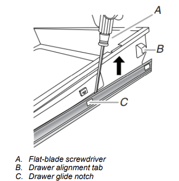
3. Repeat Step 2 on the other side. The drawer is no longer attached to the drawer glides. Using both hands, pick up the drawer to complete the removal.
To Replace:
1. Align the forward drawer notches with the notches in the drawer glides on both sides. Place the rear alignment tabs into the drawer glides on both sides.
2. Push the warming drawer or premium storage drawer in all the way.
3. Gently open and close the warming drawer or premium storage drawer to ensure it is seated properly on the glides on both sides
Storage Drawer (on some models)
The storage drawer can be removed. Before removing, make sure drawer is cool and empty.
To Remove:
1. Pull the storage drawer straight back to the drawer stop.
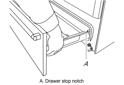
2. Lift up the front of the drawer and pull the drawer out.
To Replace:
1. Lift up the front of the drawer and place the rear of the drawer inside the range so that the drawer stop notch is behind the drawer glide.
2. Lower the drawer so that the edge of the slide rail drops into the slot in the drawer glide.
3. Slowly push the drawer into the range.
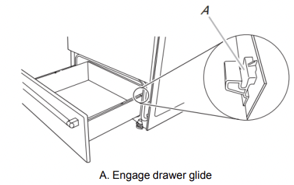
NOTE: When properly installed, the rear slides on the bottom of the drawer will engage the base rails and the drawer will not tip when items are placed in the drawer.
Oven Door
For normal range use, it is not suggested to remove the oven door. However, if removal is necessary, make sure the oven is OFF and cool. Then, follow these instructions. The oven door is heavy.
To Remove:
1. Open oven door all the way.
2. Pinch the hinge latch between two fingers and pull forward. Repeat on other side of oven door.
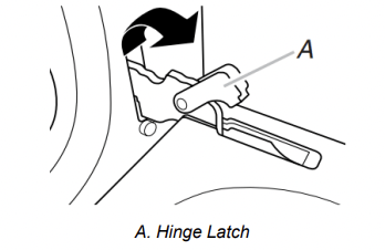
3. Close the oven door as far as it will shut.
4. Lift the oven door while holding both sides. Continue to push the oven door closed and pull it away from the oven door frame.
To Replace:
1. Insert both hanger arms into the door.
2. Open the oven door. You should hear a click as the door is set into place.
3. Move the hinge levers back to the locked position. Check that the door is free to open and close. If it is not, repeat the removal and installation procedures.
Complete Installation
1. Check that all parts are now installed. If there is an extra part, go back through the steps to see which step was skipped.
2. Check that you have all of your tools.
3. Dispose of/recycle all packaging materials.
4. Check that the range is level. See the “Level Range” section.
5. Use a mild solution of liquid household cleaner and warm water to remove waxy residue caused by shipping material. Dry thoroughly with a soft cloth. For more information, read the “Range Maintenance and Care” section.
6. Read the Quick Start Guide and online Control Guide.
7. Turn on surface burners and oven. See the Quick Start Guide and online Control Guide for specific instruction on range operation.
If Range Does Not Operate, Check the Following:
■ Household fuse is intact and tight; or circuit breaker has not tripped.
■ Range is plugged into a grounded 3-prong outlet.
■ Gas pressure regulator shutoff valve is in the “on” position.
■ Electrical supply is connected.
■ See the online “Troubleshooting” section.
8. When the range has been on for 5 minutes, check for heat. If the range is cold, turn off the range and check that the gas supply line shut-off valve is open.
■ If the gas supply line shut-off valve is closed, open it, and then repeat the 5 minute test as outlined above.
■ If the gas supply line shutoff valve is open, press the CANCEL button on the oven control panel and contact a qualified technician.
If You Need Assistance or Service:
Please reference the Quick Start Guide for contact information
GAS CONVERSIONS
Gas conversions from Natural gas to propane gas or from propane gas to Natural gas must be done by a qualified installer.
WARNING Explosion Hazard
Use a new CSA International approved gas supply line.
Install a shut-off valve.
Securely tighten all gas connections.
If connected to propane, have a qualified person make sure gas pressure does not exceed 14ʺ (36 cm) water column.
Examples of a qualified person include: licensed heating personnel, authorized gas company personnel, and authorized service personnel.
Failure to do so can result in death, explosion, or fire.
WARNING: This conversion kit shall be installed by a qualified service agency in accordance with the manufacturer’s instructions and all applicable codes and requirements of the authority having jurisdiction. If the information in these instructions is not followed exactly, a fire, explosion or production of carbon monoxide may result causing property damage, personal injury or loss of life. The qualified service agency is responsible for the proper installation of this kit. The installation is not proper and complete until the operation of the converted appliance is checked as specified in the manufacturer’s instructions supplied with the kit.
Propane Gas Conversion
WARNING Tip Over Hazard
A child or adult can tip the range and be killed.
Install anti-tip bracket to floor or wall per installation instructions.
Slide range back so rear range foot is engaged in the slot of the anti-tip bracket.
Re-engage anti-tip bracket if range is moved.
Do not operate range without anti-tip bracket installed and engaged.
Failure to follow these instructions can result in death or serious burns to children and adults.
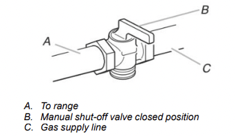
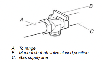
1. Turn manual shutoff valve to the closed position.
2. Unplug range or disconnect power.
To Convert Gas Pressure Regulator (Natural gas to Propane)
1. Remove the premium storage drawer, warming drawer or baking drawer. See the “Remove/Replace Drawer”, “Storage Drawer” or “Warming Drawer or Premium Storage Drawer” section.
2. Locate gas pressure regulator at rear of the drawer compartment.
NOTE: On models with a warming drawer or baking drawer, an access cover must be removed to access the gas pressure regulator.
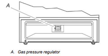
IMPORTANT: Do not remove the gas pressure regulator.
3. Remove plastic cover from gas pressure regulator cap.
4. Turn gas pressure regulator cap counterclockwise with a 5/8" (1.6 cm) combination wrench to remove.
NOTE: Do not remove the spring beneath the cap.
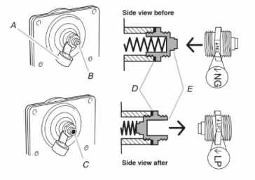
A. Plastic cover
B. Gas pressure regulator cap with solid end facing out
C. Gas pressure regulator cap with hollow end facing out
D. Washer
E. Gas pressure regulator cap
5. Turn over the gas pressure regulator cap and reinstall on regulator so that the hollow end faces out and the marking “↓LP” is facing the direction shown in the above drawing.
6. Replace plastic cover over gas pressure regulator cap.
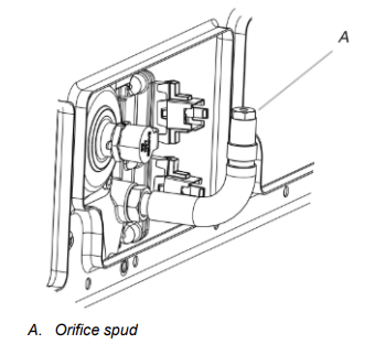
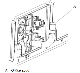
To Convert Surface Burners (Natural Gas to Propane Gas)
1. Remove burner cap.
2. Remove the burner base.
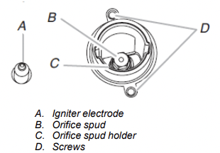
3. Apply masking tape to the end of a 9/32" (7 mm) nut driver to help hold the gas orifice spud in the nut driver while changing it. Press nut driver down onto the gas orifice spud and remove by turning it counterclockwise and lifting out. Set gas orifice spud aside.
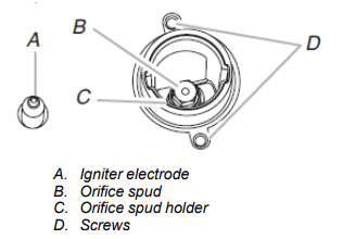
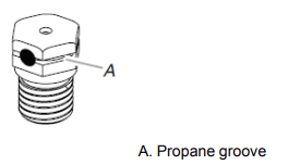
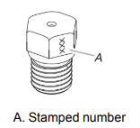
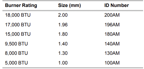
4. Remove the orifice spuds shipped in the literature package in the oven. Gas orifice spuds are stamped with a number and have a groove in the hex area. Replace the Natural gas orifice spud with the correct propane gas orifice spud.
Refer to the following chart for correct Propane gas orifice spud placement.
Propane Gas Orifice Spud Chart for Surface Burner
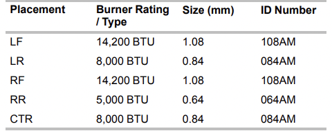
NOTE: Refer to the model/serial/rating plate located on the oven frame behind the top left side of the oven door for proper sizing of spuds for each burner location.
5. Place Natural gas orifice spuds in the orifice spud bag. IMPORTANT: Keep the Natural gas orifice spuds in case of reinstallation with Natural gas.
6. Replace the burner base.
7. Replace burner cap.
8. Repeat steps 1-7 for the remaining burners
To Convert Oven Bake Burner (Natural Gas to Propane Gas)
1. Remove the oven racks.
2. Remove 2 screws at the rear of the oven bottom.
3. Lift the rear of the oven bottom up and back until the front of the panel is away from the front frame. Remove from oven and set it aside on a covered surface.
4. Remove 2 screws from the front tabs of the flame spreader. Lift the front of the flame spreader and pull forward to remove tabs from rear of oven and set it aside on a covered surface.
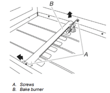
5. Remove 2 screws from the bake burner.
6. Slide the front of the bake burner to the side to remove tab from front of oven. Lift the back of the bake burner off the oven orifice, and set the bake burner aside.
7. Use a 3/8" (1 cm) nut driver or combination wrench and turn the Natural gas bake burner orifice spud counterclockwise to remove. The spud will be stamped with a “49.”
8. Replace the “49” spud with a “57” spud. Install the Propane gas bake burner orifice spud, turning it clockwise until snug.
IMPORTANT: Do not overtighten.
9. Position the back of the bake burner over the oven orifice, and slide the tab on front of the bake burner into the front of the oven.
10. Reattach the bake burner with 2 screws.
11. Insert the tabs on the rear of the flame spreader into the rear of the oven.
12. Reattach the front tabs of the flame spreader to the oven with 2 screws.
13. Position the front of the oven bottom panel toward the front frame and lower the rear of the oven bottom panel into the oven.
14. Reattach the oven bottom panel with 2 screws.
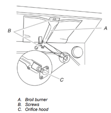
To Convert Oven Broil Burner (Natural Gas to Propane Gas)
1. Remove the screw from the broil burner
2. Remove the flame spreader.
3. Remove the broil burner from the broil burner orifice hood.
NOTE: The broil burner will hang in the back of the oven while changing the orifice hood.
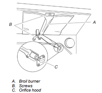
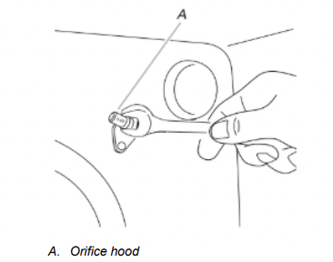
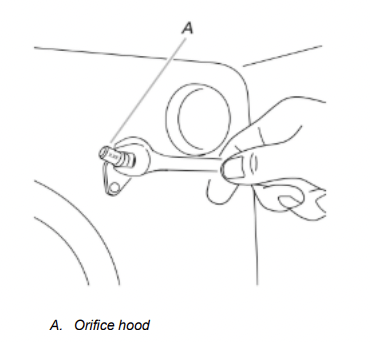
4. Use a 3/8" (1 cm) combination wrench and turn the Natural gas broil burner orifice hood counterclockwise to remove. The hood will be stamped with a “53.”
5. Replace the “53” hood with a “090” hood. Install the Propane gas broiler burner orifice hood, turning it clockwise until snug.
IMPORTANT: Do not overtighten.
6. Place the broil burner on the broil burner orifice hood and insert the broil burner ceramic igniter in the hole in the rear of the oven.
7. Position the broil burner against the top of the oven and attach it with 2 screws.
8. Replace storage drawer, warming drawer or premium storage drawer. See the “Storage Drawer” or “Warming Drawer or Premium Storage Drawer” section.
9. Replace the oven door if it has been removed. See the “Oven Door” section.
10. Replace the oven racks
Complete Installation (Natural Gas to Propane Gas)
1. Refer to the “Make Gas Connection” section for properly connecting the range to the gas supply.
2. Refer to the “Electronic Ignition System” section for proper burner ignition, operation and burner flame adjustments.
IMPORTANT: You may have to adjust the “LO” setting for each cooktop burner. Checking for proper cooktop, bake and broil burner flame is very important. The small inner cone should have a very distinct blue flame 1/4" (0.64 cm) to 1/2" (1.3 cm) long. The outer cone is not as distinct as the inner cone. Propane gas flames have a slightly yellow tip.
3. Refer to “Complete Installation” in the “Installation Instructions” section of this manual to complete this procedure.
NOTE: Make sure to save the orifices that have just been replaced in the conversion.
Natural Gas Conversion
WARNING Tip Over Hazard
A child or adult can tip the range and be killed.
Install anti-tip bracket to floor or wall per installation instructions.
Slide range back so rear range foot is engaged in the slot of the anti-tip bracket.
Re-engage anti-tip bracket if range is moved.
Do not operate range without anti-tip bracket installed and engaged.
Failure to follow these instructions can result in death or serious burns to children and adults.
1. Turn manual shutoff valve to the closed position.
2. Unplug range or disconnect power.
To Convert Gas Pressure Regulator (Propane Gas to Natural Gas)
1. Remove the premium storage drawer, warming drawer or baking drawer or premium storage drawer. See the Remove/Replace Drawer, Storage Drawer or Warming Drawer or Premium Storage Drawer section.
2. Locate gas pressure regulator at rear of the drawer compartment.
NOTE: On models with a warming drawer or baking drawer, an access cover must be removed to access the gas pressure regulator
IMPORTANT: Do not remove the gas pressure regulator.
3. Remove plastic cover from gas pressure regulator cap.
4. Turn gas pressure regulator cap counterclockwise with a 5/8" (1.6 cm) combination wrench to remove.
NOTE: Do not remove the spring beneath the cap.
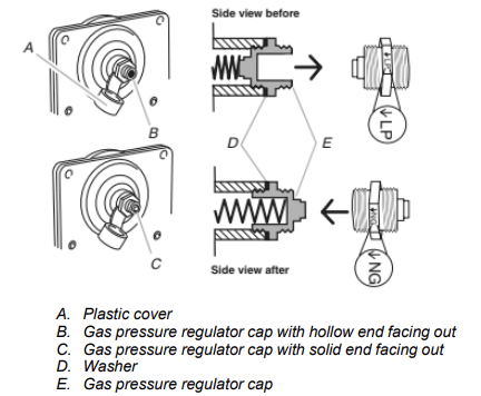
5. Turn over the gas pressure regulator cap and reinstall on regulator so that the solid end faces out and the marking “↓NG” is facing the direction shown in the above drawing.
6. Replace plastic cover over gas pressure regulator cap
To Convert Surface Burners (Propane Gas to Natural Gas)
1. Remove burner cap.
2. Remove the burner base
3. Apply masking tape to the end of a 9/32" (7 mm) nut driver to help hold the gas orifice spud in the nut driver while changing it. Press nut driver down onto the gas orifice spud and remove by turning it counterclockwise and lifting out. Set gas orifice spud aside.
4. Gas orifice spuds are stamped with a number on the side. Replace the propane gas orifice spud with the correct Natural gas orifice spud.
Refer to the following chart for the correct Natural gas orifice spud placement.
Natural Gas Orifice Spud Chart
NOTE: Refer to the model/serial/rating plate located on the oven frame behind the top right-hand side of the oven door for proper sizing of spuds for each burner location.
5. Place propane gas orifice spuds in the orifice spud bag.
IMPORTANT: Keep the propane gas orifice spuds in case of reinstallation with propane gas.
6. Replace the burner base using both screws.
7. Replace burner cap.
8. Repeat steps 1 through 7 for the remaining burners
To Convert Oven Bake Burner (Propane Gas to Natural Gas)
1. Remove the oven racks.
2. Remove 2 screws at the rear of the oven bottom.
3. Lift the rear of the oven bottom up and back until the front of the panel is away from the front frame. Remove from oven and set it aside on a covered surface.
4. Remove 2 screws from the front tabs of the flame spreader. Lift front of the flame spreader and pull forward to remove tabs from rear of oven and set it aside on a covered surface.
5. Remove 2 screws from the bake burner.
6. Slide the front of the bake burner to the side to remove tab from front of oven. Lift the back of the bake burner off the oven orifice, and set the bake burner aside.
7. Use a 3/8" (1 cm) nut driver or combination wrench and turn the Propane gas bake burner orifice spud counterclockwise to remove. The spud will be stamped with a “57.”
8. Replace the “57” spud with a “49” spud. Install the Natural gas bake burner orifice spud, turning it clockwise until snug.
IMPORTANT: Do not overtighten.
9. Position the back of the bake burner over the oven orifice, and slide the tab on front of the bake burner into the front of the oven
10. Reattach the bake burner with 2 screws.
11. Insert the tabs on the rear of the flame spreader into the rear of the oven.
12. Reattach the front tabs of the flame spreader to the oven with 2 screws.
13. Position the front of the oven bottom panel toward the front frame and lower the rear of the oven bottom panel into the oven.
14. Reattach the oven bottom panel with 2 screws.
To Convert Oven Broil Burner (Propane Gas to Natural Gas)
1. Remove the screw from the broil burner
2. Remove the broil burner from the broil burner orifice hood.
NOTE: The broil burner will hang in the back of the oven while changing the orifice hood.
3. Using a 3/8" (9.5 mm) combination wrench, turn the Propane gas broil burner orifice hood counterclockwise to remove. The hood will be stamped with a “090.”
4. Replace the “090” hood with a “53” hood. Install the Natural gas broiler burner orifice hood, turning it clockwise until snug.
IMPORTANT: Do not overtighten.
5. Place the broil burner on the broil burner orifice hood and insert the broil burner ceramic igniter in the hole in the rear of the oven.
6. Position the broil burner against the top of the oven and attach it with 2 screws.
7. Replace storage drawer or warming drawer. See the “Storage Drawer” or “Warming Drawer or Premium Storage Drawer” section.
8. Replace the oven door. See the “Oven Door” section.
9. Replace the oven racks.
Complete Installation (Propane Gas to Natural Gas)
1. Refer to the “Make Gas Connection” section for properly connecting the range to the gas supply.
2. Refer to the “Electronic Ignition System” section for proper burner ignition, operation and burner flame adjustments.
IMPORTANT: You may have to adjust the “LO” setting for each cooktop burner. Checking for proper cooktop, bake and broil burner flame is very important. Natural gas flames do not have yellow tips.
3. Refer to “Complete Installation” in the “Installation Instructions” section of this manual to complete this procedure.
NOTE: Make sure to save the orifices that have just been replaced in the conversion.
Moving the Range
WARNING Tip Over Hazard
A child or adult can tip the range and be killed.
Install anti-tip bracket to floor or wall per installation instructions.
Slide range back so rear range foot is engaged in the slot of the anti-tip bracket.
Re-engage anti-tip bracket if range is moved.
Do not operate range without anti-tip bracket installed and engaged.
Failure to follow these instructions can result in death or serious burns to children and adults.
When moving range, slide range onto cardboard or hardboard to avoid damaging the floor covering. If removing the range is necessary for cleaning or maintenance: For power supply cord-connected ranges:
1. Slide range forward.
2. Turn manual shutoff valve to the closed position.
3. Unplug the power supply cord.
4. Disconnect the gas supply tubing.
5. Complete cleaning or maintenance.
6. Reconnect the gas supply tubing.
7. Open the manual shutoff valve in the gas supply line.
8. Plug in power supply cord.
9. Slide range back so rear range foot is under anti-tip bracket.
10. Refer to the “Verify Anti-Tip Bracket Is Installed and Engaged” section to verify engagement.
11. Check that range is level.
FEATURE GUIDE
WARNING: To reduce the risk of fire, electric shock, or injury to persons, read the IMPORTANT SAFETY INSTRUCTIONS, located in your appliance's Owner's Manual, before operating this appliance.
WARNING Food Poisoning Hazard Do not let food sit for more than one hour before or after cooking. Doing so can result in food poisoning or sickness.
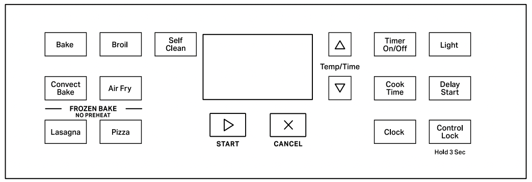
| KEYPAD |
FEATURE |
INSTRUCTIONS |
| CLOCK |
Clock |
The Clock uses a 12 hour cycle.
1. Check that the oven is off.
2. Press CLOCK.
3. Press the Temp/Time up or down arrow keypad to set the hours. Press CLOCK to switch to the minutes. Press the Temp/Time up or down arrow keypad to set the minutes.
4. Press CLOCK or the Start keypad.
|
| LIGHT |
Oven cavity light |
While the oven door is closed, press LIGHT to turn the light on and off. The oven light will come on when the oven door is opened. The oven light will not come on during the SelfCleaning cycle. |
| TIMER SET/ OFF |
Oven timer |
The Timer can be set in hours or minutes up to 9 hours and 59 minutes.
1. Press TIMER SET/OFF.
2. Press the Temp/Time up or down arrow keypad to set the length of time.
3. Press the Start keypad to begin the countdown. If enabled, end-of-cycle tones will sound at end of countdown.
4. Press TIMER SET/OFF to cancel the Timer. Do not press the Cancel keypad because the oven will turn off.
|
|
Start

|
Cooking start |
The Start keypad begins any oven function. If the Start keypad is not pressed within 10 seconds, a tone will sound and The Start keypad will blink until pressed or canceled. If Start is not pressed within 30 seconds after pressing a keypad, the function is canceled and the time of day is displayed. |
|
Cancel

|
Range function |
The Cancel keypad stops any function except the Timer and Oven Control Lockout. |
| TEMP/TIME |
Temperature and time adjust |
The Temp/Time up and down arrow keypads are used to adjust time and temperature settings. |
| BAKE |
Baking and roasting |
1. Press BAKE.
2. Press the Temp/Time up or down arrow keypad until desired temperature is reached. A tone will sound if the minimum or maximum temperature is reached.
3. Press the Start keypad.
4. To change the temperature, repeat Step 2. Press the Start keypad.
5. Press the Cancel keypad when finished.
NOTE: The convection fan will shut off when the oven door is opened. If the oven door remains open for too long, the heating elements will shut off until the oven door is closed. All timers, including any active Cook Time or Timed Cook functions, will continue to count down.
|
| CONVECT BAKE |
Convection baking and roasting |
1. Press CONVECT BAKE.
2. Press the Temp/Time up or down arrow keypad until desired temperature is reached. A tone will sound if the minimum or maximum temperature is reached.
3. Press the Start keypad.
4. To change the temperature, repeat Step 2. Press the Start keypad.
5. Press the Cancel keypad when finished.
NOTE: The convection fan will shut off when the oven door is opened. If the oven door remains open for too long, the heating elements will shut off until the oven door is closed. All timers, including any active Cook Time or Timed Cook functions, will continue to count down.
|
| FROZEN BAKE |
Prepackaged food |
1. Position the food on a flat rack in the oven on rack position 3 or 4. See the “Positioning Racks and Bakeware” section.
NOTE: Cook only 1 package of frozen food at a time when using Frozen Bake™ Technology.
2. Press FROZEN BAKE LASAGNA or PIZZA.
3. Press the Temp/Time up or down arrow keypad to set the temperature as recommended on the food packaging.
4. Press COOK TIME.
5. Press the Temp/Time up or down arrow keypad to set the maximum cook time as recommended on the food packaging.
6. Press the Start keypad. The range will calculate the best cook time based on the current oven temperature.
NOTE: The cook time that appears in the display is the estimated required cook time as calculated by the oven control. It may be different than the time you entered. A beep will alert you to check the food’s doneness with at least 2 minutes remaining on the timer. Follow the prompts on the display to select more time if desired.
7. Press the Start keypad to start the calculated time.
8. At the end of the cook time, a beep will alert you to check the food’s doneness. When “End” is displayed and is flashing, you can add more time, if desired. Press the up or down arrow keypad to set the time, then press START. If more time is not added, the bake element will turn off.
NOTE: Pressing Cancel will exit the Frozen Bake™ cycle.
9. Press the Cancel keypad when finished.
NOTE: The convection fan will shut off when the oven door is opened. If the oven door remains open for too long, the heating elements will shut off until the oven door is closed. All timers, including any active Cook Time or Timed Cook functions, will continue to count down.
|
| BROIL |
Broiling |
1. Press BROIL.
2. Press the Temp/Time up or down arrow keypad until desired temperature is reached. A tone will sound if the minimum or maximum temperature is reached.
3. Press the Start keypad.
4. To change the temperature, repeat Step 2 and press the Start keypad.
5. Press the Cancel keypad when finished.
NOTE: The convection fan will shut off when the oven door is opened. If the oven door remains open for too long, the heating elements will shut off until the oven door is closed. All timers, including any active Cook Time or Timed Cook functions, will continue to count down.
|
| AIR FRY |
Air Frying |
1. Press AIR FRY.
2. Press the Temp/Time up or down arrow keypad until desired temperature is reached. A tone will sound if the minimum or maximum temperature is reached.
3. Press the Start keypad.
4. To change the temperature, repeat Step 2. Press the Start keypad.
5. Press the Cancel keypad when finished.
NOTE: The convection fan will shut off when the oven door is opened. If the oven door remains open for too long, the heating elements will shut off until the oven door is closed. All timers, including any active Cook Time or Timed Cook functions, will continue to count down.
|
| DELAY START |
Delayed start |
Delay Start is used to enter the starting time for an oven function with a delayed start. Delay Start should not be used for foods such as breads and cakes because they may not bake properly.
To set a Timed Cook or a Delayed Timed Cook, see “Cook Time” section.
|
| COOK TIME |
Timed cooking |
Cook Time allows the oven to be set to turn on at a certain time of day, cook for a set length of time, and/or shut off automatically.
To set a Timed Cook or a Delayed Timed Cook, see “Cook Time” section.
|
| CLEAN |
Self-Cleaning cycle |
See the “Self-Cleaning Cycle” section in the Owner’s Manual. |
| CONTROL LOCK (Hold 3 sec) |
Oven control lockout |
1. Check that the oven and cooktop are off.
2. Press and hold CONTROL LOCK for 3 seconds.
3. A tone will sound and a lock will be displayed.
4. Repeat to unlock. No keypads will function with the controls locked.
|
OVEN USE
The normal operation of the range will include several noises that may be heard each time the Bake or Broil burners ignite during the cooking cycle:
- Gas valves may make a “popping” sound when opening or closing.
- Igniters will “click” several times until a flame is sensed.
- A “poof” sound is heard when a bake or broil burner ignites.
Odors and smoke are normal when the oven is used the first few times or when it is heavily soiled.
IMPORTANT: The health of some birds is extremely sensitive to the fumes given off. Exposure to the fumes may result in death to certain birds. Always move birds to another closed and wellventilated room.
NOTE: On some models: The convection fan will shut off when the oven door is opened. If the oven door remains open for too long, the heating elements will shut off until the oven door is closed. All timers, including any active Cook Time or Timed Cook functions, will continue to count down.
Electronic Oven Controls
Control Display
The display will flash when powered up or after a power loss.
Press the Cancel keypad to clear. When the oven is not in use, the time of day is displayed.
Fahrenheit and Celsius
The temperature is preset to Fahrenheit but can be changed to Celsius.
To change: Press and hold the Temp/Time up arrow keypad for seconds. “°C” or “°F” will appear on the display. Repeat to change back.
To exit mode, press the Cancel keypad.
Keypress Tones
Activates or turns off the tones when a keypad is pressed.
To change: Press and hold LIGHT for 5 seconds. Repeat to change back.
To exit mode, press the Cancel keypad.
Demo Mode
IMPORTANT: This feature is intended for use on the sales floor with 120 V power connection and permits the control features to be demonstrated without the oven turning on. If this feature is activated, the oven will not work.
To change: Press the Cancel keypad, the Cancel keypad, the Temp/Time up arrow keypad, and TIMER SET/OFF. Repeat to change back and end Demo mode.
Tones
Tones are audible signals, indicating the following:
One Tone
- Valid keypad press
- Oven is preheated (long tone)
- Function has been entered.
- Reminder (on some models), repeating every 20 seconds after the end-of-cycle tones
Three Tones
Four Tones
On some models: Use the Clock/Tools keypad to change the tone settings.
Oven Temperature Offset Control
IMPORTANT: Do not use a thermometer to measure oven temperature. Elements will cycle on and off as needed to provide consistent temperature but may run slightly hot or cool at any point in time due to this cycling. Most thermometers are slow to react to temperature change and will not provide an accurate reading due to this cycling.
The oven provides accurate temperatures; however, it may cook faster or slower than your previous oven, so the temperature can be adjusted to personalize it for your cooking needs. It can be changed to Fahrenheit or Celsius.
To Adjust Oven Temperature:
- Press and hold the Temp/Time down arrow keypad for seconds until the oven display shows the current setting, for example “0°F CAL” or “00.”
- Press the Temp/Time up or down arrow keypad to increase or to decrease the temperature in 5°F (3°C) amounts. The adjustment can be set between 30°F (18°C) and -30°F (-18°C).
- Press the Start keypad.
Sabbath Mode
For guidance on usage and a complete list of models with Sabbath mode.
The Sabbath mode sets the oven to remain on in a Bake setting until turned off. A Timed Bake can also be set to keep the oven on for only part of the Sabbath. The Oven Control Lockout feature will be disabled during the Sabbath mode. After the Sabbath mode is set, no tones will sound, the display will not show the temperature, the Kitchen Timer mode will be canceled (if active), and only the following keypads will function:
- Temp/Time up and down arrow keypads
- Cancel
When the oven door is opened or closed, the oven light will not turn on or off and the heating elements will not turn on or off immediately.
When power is restored after a power failure, the oven will return to Sabbath mode and remain Sabbath compliant with the bake elements off until the Cancel keypad is pressed.
Pressing the Cancel keypad at any time returns the oven to the normal cooking mode (not Sabbath compliant).
Before entering the Sabbath mode, it must be decided if the oven light is to be on or off for the entire Sabbath mode period. If the light is on when entering Sabbath mode, it will remain on for the entire time Sabbath mode is in use. If the light is off when entering Sabbath mode, it will remain off for the entire time Sabbath mode is in use. Opening the oven door or pressing LIGHT will not affect the oven light once Sabbath mode has been entered.
On the Holiday, the oven temperature can be changed once the oven is in Sabbath mode by pressing the Temp/Time up or down arrow keypad. The oven temperature will change 25°F (14°C) each time the Temp/Time up and down arrow keypads are pressed. Press the Start keypad to activate the new temperature.
The display will not change and there will be no sounds during this adjustment.
To Activate and Bake Using Sabbath Mode:
- Press BAKE.
- Press the Temp/Time up or down arrow keypad.
- Press the Start keypad.
- Press and hold TIMER SET/OFF for 5 seconds. “SAb” will flash in the display.
- Press the Start keypad while “SAb” is flashing to enter Sabbath mode; otherwise, the entire cycle cancels out. “SAb” will stop flashing and remain on in the display. The oven is now in Sabbath mode and is Sabbath compliant.
Pressing the Cancel keypad at any time returns the oven to the normal cooking mode (not Sabbath compliant).
NOTE: On some models: If “SAb” does not appear in your display, the Sabbath mode is not active. After Sabbath mode is deactivated, you must activate Sabbath mode by completing steps 1 through 5.
To Set a Timed Bake Using Sabbath Mode (on some models):
- Press BAKE.
- Press the Temp/Time up or down arrow keypad to enter a temperature other than the one displayed.
- Press COOK TIME. The Cook Time oven indicator light will light up.
- Press the Temp/Time up or down arrow keypad to enter a cook time length.
- Press the Start keypad.
- Press and hold TIMER SET/OFF for 5 seconds. “SAb” will flash in the display.
- Press the Start keypad while “SAb” is flashing to enter Sabbath mode; otherwise, the entire cycle cancels out. “SAb” will stop flashing and remain on in the display. The oven is now in Sabbath mode and is Sabbath compliant. The Bake, On, and Cook Time indicator lights will be displayed.
When the set cook time ends, the oven will shut off automatically and the indicator lights will turn off, indicating the end of the cycle.
Pressing the Cancel keypad at any time returns the oven to the normal cooking mode (not Sabbath mode compliant).
NOTE: If “SAb” does not appear in your display, the Sabbath mode is not active. After Sabbath mode is deactivated, you must activate Sabbath mode by completing steps 1 through 5.
To Set a Delayed Timed Bake Using Sabbath Mode (on some models):
- Press BAKE.
- Press the Temp/Time up or down arrow keypad to enter a temperature other than the one displayed.
- Press COOK TIME. The Cook Time oven indicator light will light up.
- Press the Temp/Time up or down arrow keypad to enter a cook time length.
- Press DELAY START. The Delay indicator light will light up.
- Press the Temp/Time up or down arrow keypad to enter a start time.
- Press the Start keypad.
- Press and hold TIMER SET/OFF for 5 seconds. “SAb” will flash in the display.
- Press the Start keypad while “SAb” is flashing to enter Sabbath mode; otherwise, the entire cycle cancels out. “SAb” will stop flashing and remain on in the display. The oven is now in Sabbath mode and is Sabbath compliant. The On and Delay indicator lights will be displayed.
When the start time is reached, the Bake, On, and Cook Time indicator lights will automatically turn on. When the set cook time ends, the oven will shut off automatically and the indicator lights will turn off, indicating the end of the cycle.
Pressing the Cancel keypad at any time returns the oven to the normal cooking mode (not Sabbath mode compliant).
NOTE: On some models: If “SAb” does not appear in your display, the Sabbath mode is not active. After Sabbath mode is deactivated, you must activate Sabbath mode by completing steps 1 through 5.
Positioning Racks and Bakeware
Use the following illustration as a guide.
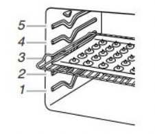
Rack Positions
- Rack 5: Toasting bread or broiling thin, non-fatty foods
- Rack 4: two-rack baking and broiling
- Rack 3: Air fry basket, most baked goods on a cookie sheet, muffin pan, or jelly roll pan; layer cakes; broiling chicken pieces
- Rack 2: Pies, casseroles, yeast bread, quick breads, frozen convenience foods, and two-rack baking
- Rack 1: Roasting large and small cuts of meat and poultry
Bakeware
To cook food evenly, hot air must be able to circulate. Allow cm) of space around bakeware and oven walls. Make sure that no bakeware piece is directly over another.
Multiple Rack Cooking
Two-rack: Use rack positions 2 and 4 or 2 and 5.
Air Fry Basket
When using the Air Fry feature, position the air fry basket on top of a large baking sheet. Place basket and sheet in the middle of the oven to increase air flow and circulation. Avoid using more than one basket to avoid uneven cooking.
Baking and Roasting
Preheating
When beginning a Bake, Convect Bake, or Convect Roast cycle, the oven will begin preheating after Start is pressed. The oven will take approximately 12 to 15 minutes to reach 350°F (177°C) with all of the oven racks provided with your oven inside the oven cavity. Higher temperatures will take longer to preheat. The preheat cycle rapidly increases the oven temperature. The actual oven temperature will go above your set temperature to offset the heat lost when your oven door is opened to insert food. This ensures that when you place your food in the oven, the oven will begin at the proper temperature. Insert your food when the preheat tone sounds. Do not open the door during preheat before the tone sounds.
Oven Temperature
While in use, the oven elements will cycle on and off as needed to maintain a consistent temperature, but they may run slightly hot or cool at any point in time due to this cycling. Opening the oven door while in use will release the hot air and cool the oven which could impact the cooking time and performance. It is recommended to use the oven light to monitor cooking progress.
NOTE: On models with convection, the convection fan may run in the non-convection Bake mode to improve oven performance.
The convection fan will shut off when the oven door is opened. If the oven door remains open for too long, the heating elements will shut off until the oven door is closed. All timers, including any active Cook Time or Timed Cook functions, will continue to count down.
Temperature Management System
The Temperature Management System electronically regulates the oven heat levels during preheat and bake to maintain a precise temperature range for optimal cooking results. The bake and broil elements or burners cycle on and off in intervals. On convection range models, the fan will run while preheating and may be cycled on and off for short intervals during bake to provide the best results. This feature is automatically activated when the oven is in use.
Before baking and roasting, position racks according to the Positioning Racks and Bakeware” section. When roasting, it is not necessary to wait for the oven preheat cycle to end before putting food in unless it is recommended in the recipe.
Broiling
NOTE: The convection fan will shut off when the oven door is opened. If the oven door remains open for too long, the heating elements will shut off until the oven door is closed. All timers, including any active Cook Time or Timed Cook functions, will continue to count down.
When broiling, preheat the oven for 5 minutes before putting food in unless recommended otherwise in the recipe. Position food on grid in a broiler pan, then place it in the center of the oven rack.
IMPORTANT: Close the door to ensure proper broiling temperature.
Changing the temperature when broiling allows more precise control when cooking. The lower the broil setting is, the slower the cooking. Thicker cuts and unevenly shaped pieces of meat, fish, and poultry may cook better at lower broil settings. Use racks 4 or for broiling. Refer to the “Positioning Racks and Bakeware” section for more information.
On lower settings, the broil element will cycle on and off to maintain the proper temperature.
- For best results, use a broiler pan and grid. It is designed to drain juices and help avoid spatter and smoke.
If you would like to purchase a broiler pan, one may be ordered. Please refer to the Quick Start Guide for contact information.
NOTE: Odors and smoke are normal the first few times the oven is used or if the oven is heavily soiled.
Convection Baking, Roasting and Air Frying
NOTE: The convection fan will shut off when the oven door is opened. If the oven door remains open for too long, the heating elements will shut off until the oven door is closed. All timers, including any active Cook Time or Timed Cook functions, will continue to count down.
During convection baking, roasting or air frying the bake and broil elements or burners cycle on and off in intervals to maintain the oven temperature while the fan circulates the hot air.
If the oven door is opened during convection baking or roasting, the fan will turn off immediately. It will come back on when the oven door is closed.
NOTE: The convection fan will turn on approximately 5 minutes into any convection cycle.
Cook Time
To Set a Timed Cook:
- Press BAKE. The Bake indicator light will light up.
- Press the Temp/Time “up” or “down” arrow keypad to enter a temperature other than the one displayed.
- Press COOK TIME. The Cook Time oven indicator light will light up.
- Press the Temp/Time “up” or “down” arrow keypad to enter the length of time to cook.
- Press the Start keypad. The display will count down the time. When the time ends, the oven will shut off automatically.
- Press the Cancel keypad to clear the display.
To Set a Delayed Timed Cook:
Before setting, make sure the clock is set to the correct time of day. See “Clock” keypad feature in the “Feature Guide” section.
- Press BAKE.
- Press the Temp/Time “up” or “down” arrow keypad to enter a temperature other than the one displayed.
- Press COOK TIME. The cook time oven indicator light will light up.
- Press Temp/Time “up” or “down” arrow keypad to enter the length of time to cook.
- Press DELAY START. The Delay Oven indicator light will light up.
- Press Temp/Time “up” or “down” arrow keypad to enter the time of day to start.
- Press the Start keypad. When the start time is reached, the oven will automatically turn on. The Temperature and/or Cook Time settings can be changed anytime after the oven turns on by repeating steps and pressing the Start keypad. To change to a different delay time, cancel the features and repeat steps 1-7. When the set cook time ends, the oven will shut off automatically.
- Press the Cancel keypad to clear the display.