Loading ...
Loading ...
Loading ...
Version 20190806 Page
5
WIRING INSTRUCTIONS
ONLY qualified electrician / gas technician with the knowledge of gas appliances and gas valves that are permitted to install
the remote control system. Incorrect wiring installation will damage the gas valve, electronic module of gas appliance and
also the remote receiver.
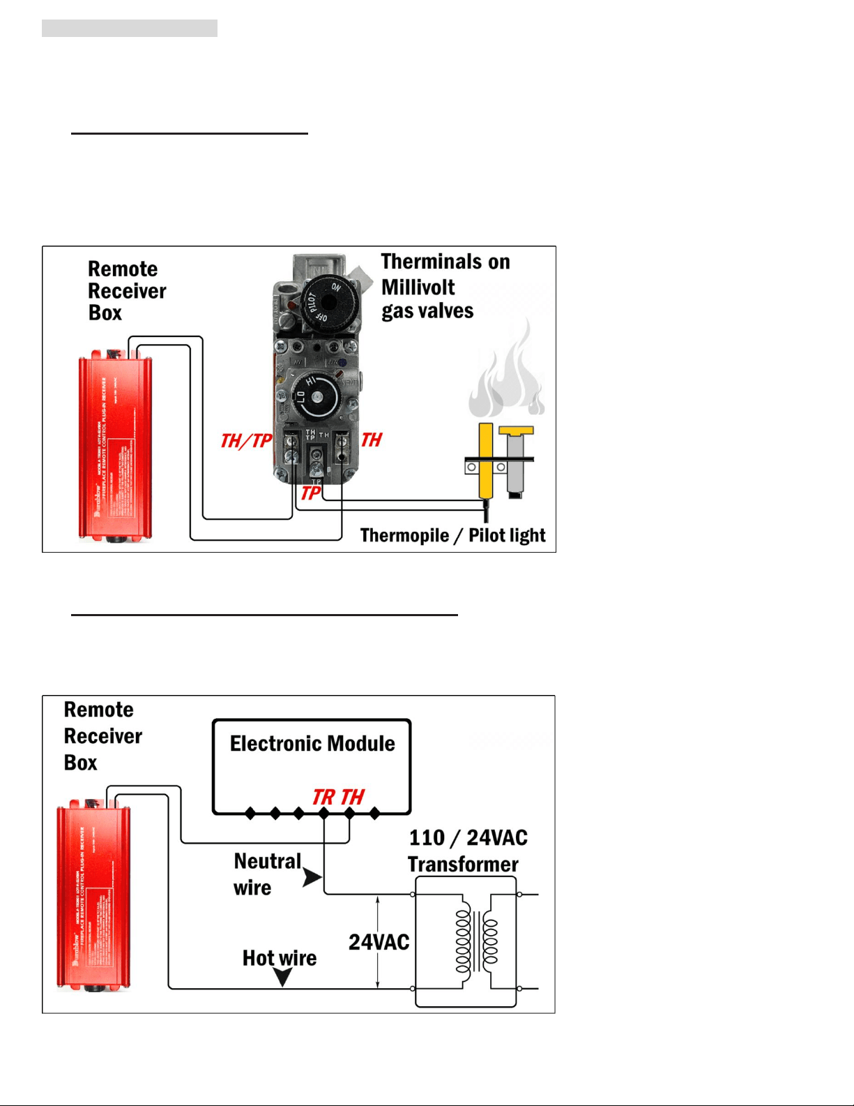
a. WIRING MILLIVOLT VALVE (Fig. 10)
Connect the two 18 gauge stranded or solid wires of the Remote receiver box to the Millivolt gas valve at the TH & TH/TP
terminals on the terminal block. It does not matter which wire go to which terminal.
The remote receiver box‘s operation is similar to a thermostat that also turn the gas valve ON and OFF based on the input
signals from TH & TH/TP terminals. Transmitter sends signals to receiver box, and receiver box pass the signals to Millivolt
valve to function the ON and OFF of fire / heater.
Fig. 10
b. WIRING ELECTRONIC SPARK IGNITION MODULE (Fig. 11)
Connect a 24VAC transformer in series to the TR (transformer) terminal on the ELECTRONIC MODULE. Connect the hot
wire from the 24VAC transformer to either of the wire terminals on the remote receiver box. Connect another wire between
receiver wire terminal and the TH (thermostat) terminal on the ELECTRONIC MODULE.
Fig. 11
Loading ...
Loading ...
Loading ...