Connect this pump to a grounded circuit equipped with a ground fault circuit interrupt (GFCI) device. Make sure the outlet is within range of power cord. Do not use extension cords.
Before installing this product, have the electrical circuit checked by an electrician to ensure proper grounding.
Ensure the water source and piping are clear of sand, dirt, mud and scale. Debris will clog pump and void warranty.
Failure to protect pump and piping from freezing could cause severe damage and will void the warranty.
Make sure that the pump is accessible and that the indicator lights on the control panel are visible.
Make sure there is adequate ventilation for the motor to ensure proper cooling
Do not pump dry.
INSTALLATION
REPLACING OLD PUMP
Drain and remove piping from old pump. Check in the piping for rust, scale etc. Replace iF necessary.
Install the new pump making sure all pipe connections are air and water tight. Use pipe joint compound on Teflon tape on all pipe connections.
NOTE: Do not use pipe joint compound on plastic pipe/fittings or electronic control as it can degrade the plastic over time. Only use teflon tape on plastic pipe/fittings or electronic control. Make sure all piping is properly supported and the pump is on a level and supported surface.
NOTE: If the suction pipe can suck air, the pump will not be able to pull water from the source.
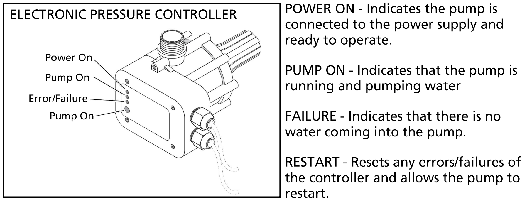
ELECTRONIC PRESSURE CONTROLLER
The automatic pressure controller protects against the following situations
Run dry operation
Frequent Stars caused by small pressure loss in the system
Pressure drop
Overheating
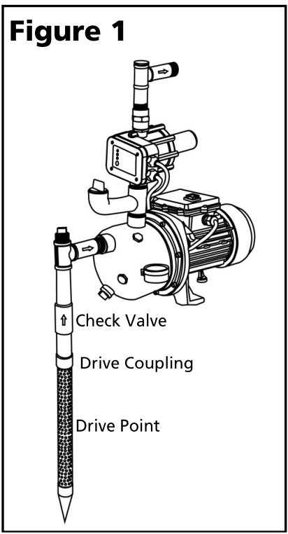
Typical driving well point installation
Drive the point using coupling and a drive cap. Do not use regular pipe fittings as the threads may strip out due to the force of driving the point.
Position the pump as close as possible to the water source to keep suction lift as low as possible.
Install a priming tee with a plug on the suction pipe from the water source as shown in figure 1. An inline check valve should also be installed on the suction line going to the pump. Install a union or other fitting that will allow the pump to be easily disassembled from the piping for easy servicing. Make sure Teflon tape or pipe joint compound is used on all joints.
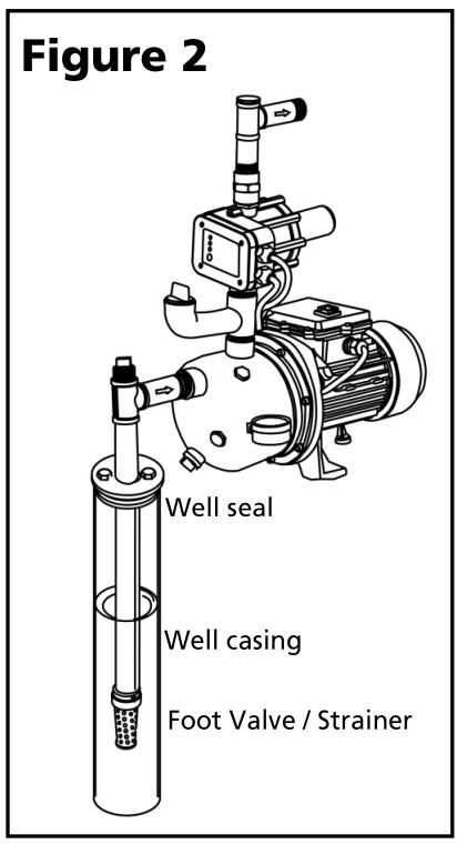
Typical case well installation
Install a foot valve with strainers on the first section of pipe and lower it into the well.
Add enough pipe until the foot well is about 10 ft below the water level. Make sure the foot valve does not rest on the bottom of the well.
Install a priming tee with a plug on the suction pipe from the water source. Install a union to allow the pump to be easily disassembled from the piping for easy servicing. Make sure Teflon tape or pipe joint compound is used on all joints
Install a well seal to prevent debris and other contaminants from entering the well
Run piping from the discharge tee on the pump housing to the household water piping
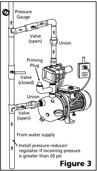
Pressure boost installation
For a pressure boost application it is recommended to plumb the pump as per the diagram of figure 3. This will allow for easy servicing or bypass of the pump. NOTE: The suction and discharge ports on the pump are 1" FNPT. Depending on the size of the incoming pipe you may need to use adapters on the ports to accommodate the size.
Install a pressure gauge as shown to monitor the pressure in the piping.
NOTE: if the incoming pressure is greater than 20 psi install a pressure reducer/regulator (not shown) on the left side of the piping before the valve. Adjust the reducer/regulator to 20 psi to prevent excess pressure on the piping.
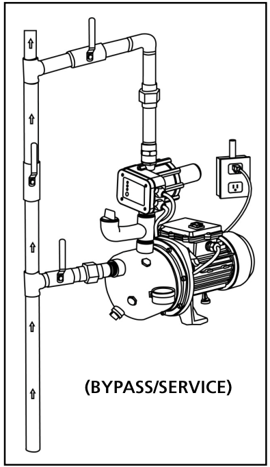
Bypassing the pump/service
To bypass the pump for service, close the valves going into the suction part on the pump and the valve on the discharge line.
The pump can be easily drained and removed at this time without interrupting water service to the system.
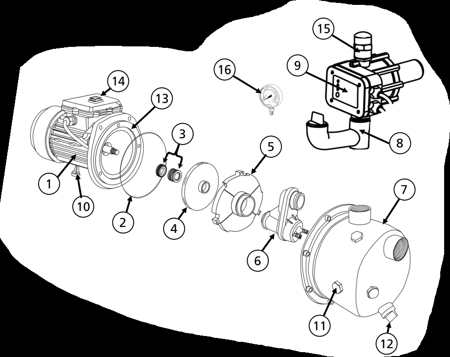
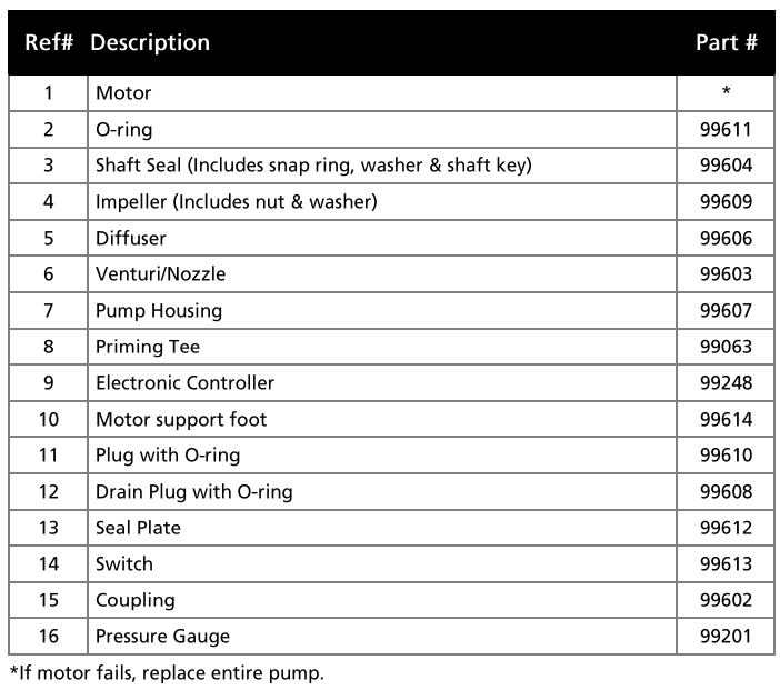
REPLACEMENT PARTS
OPERATION
PRIMING
Remove the priming plug on the tee fitting between the pump and the electronic controller.
Fill the housing/piping with clean water until water can be seen at the top of the fitting. Secure priming plug to the tee fitting.
ELECTRICAL CONNECTIONS
1 Plug the power cord into a grounded receptacle. The use of a GFCI is highly recommended and maybe required by local codes.
2 Once connected to the receptacle, the on-off switch and the indicator lights will illuminate on the electronic controller.
3 Turn the switch on the pump motor to the on position. The pump should turn on and start to pump water
NOTE: on initial startup after priming, it may take 10 to 30 seconds depending on amount of air in the piping for water to stop flowing. After initial start up/priming the pump will deliver water immediately after it's turned on. If the pump does not start, press the restart button on the electronic controller. Open a faucet or valve to bleed any air that may be trapped in the piping
4 The pump should shut off approximately 10 seconds after the valve/faucet etc is shut off/closed. It is normal to the pump to run for this amount of time after water flow stops. This delay prevents the pump from rapid cycling when faucets are being turned on and off quickly.
MAINTENANCE
1 Maintain adequate ventilation for the pump motor.
2 The motor bearings are permanently lubricated at the factory. Additional lubrication is not required.
3 Always protect pump and piping against freezing temperatures. If there is any danger of freezing, drain the system.
Disconnect suction and discharge lines from pump.
Remove plug from lower front face of pump.
Drain a piping below the frost line or store piping indoors.
Store pump indoors
4 The motor has no Auto reset thermal overload protector that protects the motor from damage in an overheat situation. The projector will Auto reset when motor cools. If the overload protector repeatedly trips, check the pump for possible causes (low voltage, clogged impeller, etc.).
TROUBLESHOOTING
PROBLEM
POSSIBLE CAUSES
HOW TO CORRECT
If the pump does not start or run
Pump is not plugged in, switch/breaker is off
Plug pump in or turn on switch/ breaker
Check for blown fuses or tripped circuit breakers or tripped GFCI outlets
Replace fuse, reset breaker, reset GFCI
Wire connections are loose or wired incorrectly
Tighten connections or re-wire following wiring diagram
Motor runs hot and thermal overload protector turns pump off
Motor is not properly vented
Make sure there is adequate room for air to circulate around the pump
Line voltage is too low
Check voltage at receptacle, increase wire gauge if necessary.
If the pump runs but moves little or no water
Loss of prime
Re-prime if necessary.
Air lock in suction line
Make sure horizontal piping between the pump and the well pitches upward towards the pump. Otherwise an airlock may form
Leak in suction line
Check all connections for leaks. Make sure all connections are air tight.
Discharge or suction pipes may be clogged or corroded
Remove clog or replace pipes if necessary
Vertical distance from the pump to the water is greater than 25 feet
Move pump closer to water source or shorten length of hose
Intake screen/foot valve is obstructed
Clean or replace if necessary
Foot valve or check valve is stuck in the closed position
Inspect, repair or replace if necessary
Foot valve or check valve is installed backwards
Make sure valve is installed in the correct direction of flow
Worn, damaged or clogged pump parts (Injector, impeller, diffuser, seal, etc.)
Inspect for wear, damage or clog and clean or replace if necessary
Foot valve is buried in sand or mud
Raise above surface bottom
Water level source is too low
Move suction hose
Pipes are frozen
Thaw pipes, heat pump house or bury pipes below frost line