Loading ...
Loading ...
Loading ...
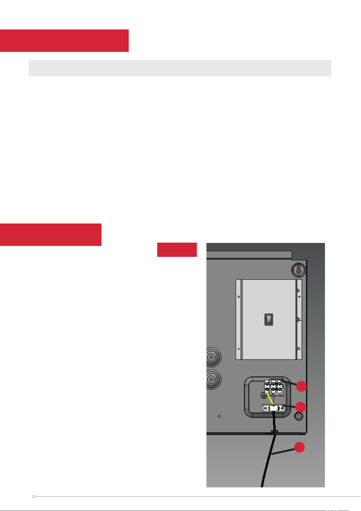
Wiring
See Fig. 3
Component
A. Terminal Block
B. Cable Clamp
C. Power Supply Cable
After ensuring the electricity supply is not live, electrical connections can be made,
either to an adjacent double-pole switch having a contact separation of at least
3mm in all poles or to a plug-top for use in a standard 13A socket.
If the latter: Connect Green and Yellow wire to plug terminal marked E or Green or
Green and Yellow. Connect Blue wire to plug terminal marked N or Black. Connect
Brown wire to plug terminal marked L or Red.
Ret cover, rst hooking top over the back of the unit and then securing the bottom
by retting the two screws under the bottom edge.
The appliance is now ready for use and the electricity supply can be reinstated.
WARNING: This appliance must be earthed
Electrical
A
C
B
Fig. 3
8
Loading ...
Loading ...
Loading ...