Loading ...
Loading ...
Loading ...
WARNING: THIS APPLIANCE MUST BE EARTHED
The use of an extension lead or multi-plug adaptor is
not advised when connecting this product to the mains.
Connection through these devices could lead to risk of
overloading, overheating and even fire at the extension
lead or adaptor due to inadequate connection quality.
This heater must be used on an AC (~) supply only and
the voltage marked on the heater must correspond to
the supply voltage. This heater is fitted with a rewirable
plug incorporating a 10/13 amp fuse. In the event of
replacing the fuse in the plug supplied, an equivalent
10/13 amp fuse approved by ASTA to BS 1362 must
be used. If any other type of plug is used, a 15 amp
fuse must be fitted in the plug, the adaptor, or at the
distribution board.
IMPORTANT: If the plug is not suitable for your socket,
the 13 amp plug should be removed. Before wiring
the appropriate plug, please note that the wires in
this mains lead are coloured in accordance with the
following code:
GREEN AND YELLOW: EARTH
BLUE: NEUTRAL
BROWN: LIVE
Connect the GREEN AND YELLOW wire to the
terminal marked ‘E’ or by the earth symbol , or
coloured GREEN or GREEN AND YELLOW. Connect
the BROWN wire to the terminal marked ‘L’ or coloured
RED. Connect the BLUE wire to the terminal marked
‘N’ or coloured BLACK.
The heater is designed for operation on an AC
electricity supply, and is suitable for use in domestic
dwellings and similar indoor locations.
The heater is supplied with feet and wall brackets to
provide the customer with the flexibility to choose
between portable or installed use. A rotary selector
switch provides the ability to select between Lo and
High heat output, each model contains a seven day
electronic timer with an integrated room sensing
thermostat. It is supplied with a cord and plug and
is ready for use once the feet have been fitted or the
heater is mounted correctly.
The ML Convector can be used as a portable heater
or can be installed.
For portable use, always ensure that the heater is
stood on a firm, level base near to, but not directly
underneath a suitable mains supply socket.
Ensure that curtains and furniture are not positioned
close to the chosen position.
We recommend that the heater should be wall-
mounted in rooms where children may be left
unattended, see ‘Important Safety Advice’.
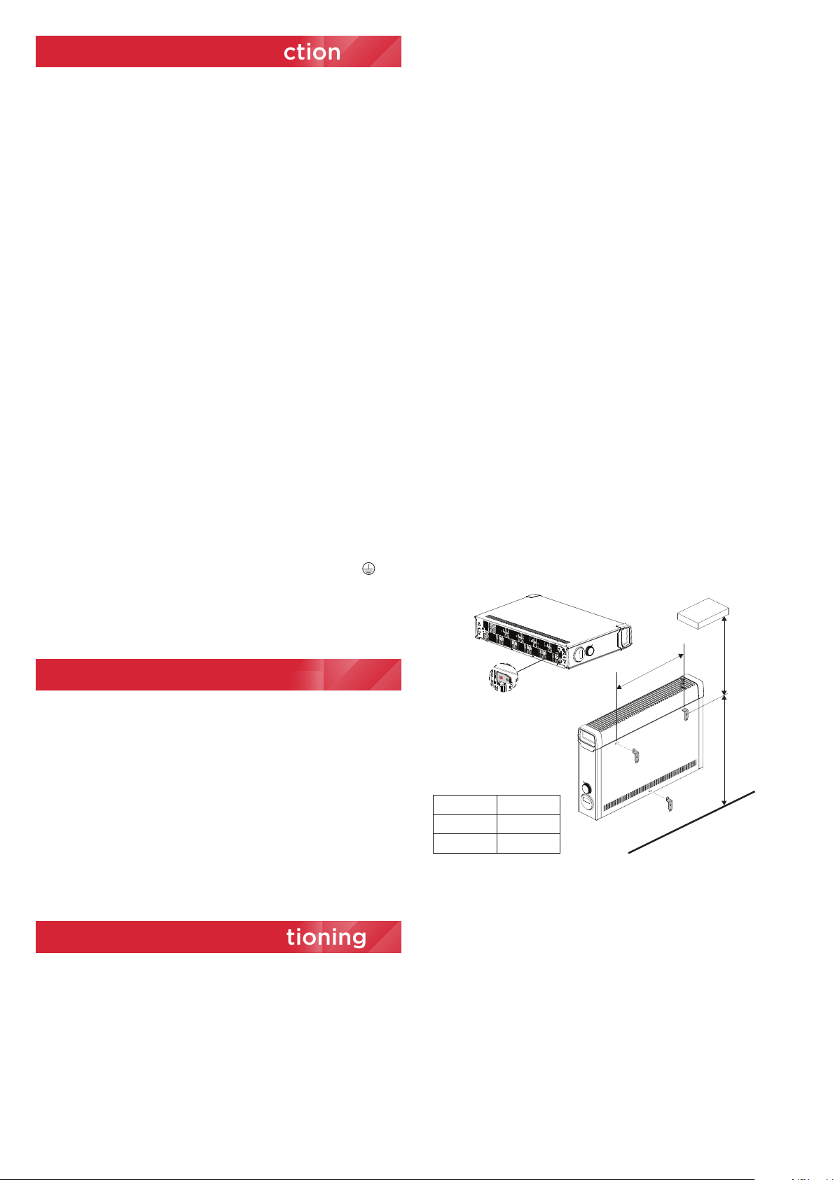
(X)
ML2*** 358
ML3*** 478
512
Min.
593
Min.
(X)
Min.
Shelf
Electrical Connection
General
If young children, the aged or infirm are likely to
be left in the vicinity of the heater, we advise that
the adequate precautions should be taken. We
recommend that a guard be fitted to ensure contact
with the heater is avoided and objects cannot be
inserted into the product.
WARNING: PLEASE ENSURE THE MINIMUM CLEARANCE
DIMENSIONS INDICATED IN Fig.1 ARE MAINTAINED
WALL MOUNTING
The brackets for wall mounting the heater are supplied fitted
to the base of the heater. To wall mount the appliance, first
remove the brackets as follows:
Lay the heater on its back and remove the screw holding the
brackets in place. The brackets can then be removed from the
heater.
Select a suitable position on a wall, close to a suitable power
socket, making sure that the minimum clearances outlined in
Fig.1 are maintained.
The position of the top two wall mounting brackets can be
marked using the dimensions included in Fig.2 for reference.
Drill and fix the top two brackets to the wall using suitable
screw fixings.
Locate the heater on the top brackets and allow it to hang in
place. Fit the bottom bracket into the slot in the heater and
then mark and fix it to the wall.
Note: The heater should be hanging on the top brackets with
the bottom bracket in position before the bottom bracket is
fixed to the wall.
Fig. 2
PORTABLE USE
WARNING The heater must only be operated with the feet
securely fitted and in the upright position.
Never use the heater as a portable appliance without the
feet securely fitted using the screws provided.
To assemble the feet, lay the heater on its back and
remove the wall mounting brackets - see Fig.3, these
can be discarded or stored for future use.
Remove the two foot fixing screws, highlighted in
Fig.3. Assemble the feet by pressing them firmly into
the convector body as indicated in Fig.3, the foot
should clip into position.
Assembly and Positioning
Loading ...
Loading ...
Loading ...