Loading ...
Loading ...
Page 3 of 8
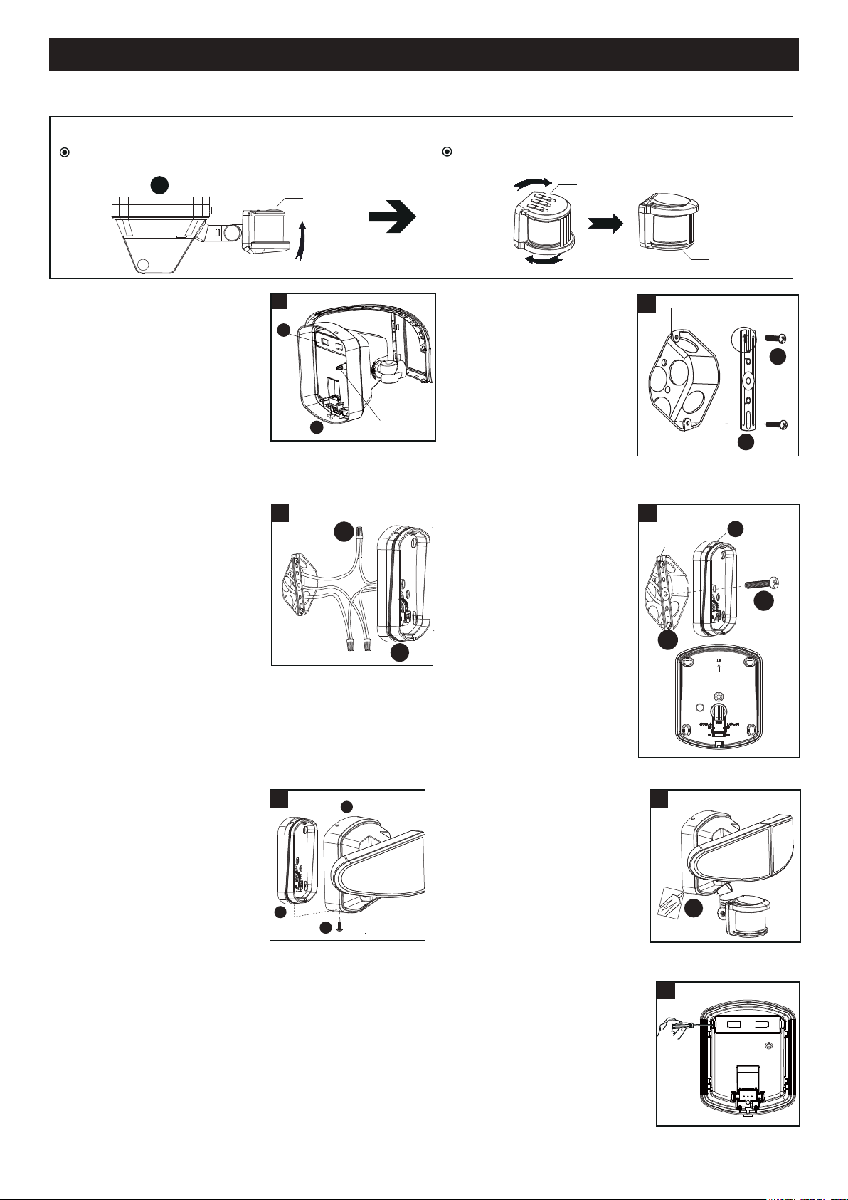
ASSEMBLY INSTRUCTIONS (continued)
2. Install the mounting strap
(BB) to the outlet box with
the stamped word “FRONT”
facing away from the outlet
box, using two mounting
screws (AA) that best fit the
outlet box. Backplate should
sit flush against wall surface
when secured. (Choose one
matching pair of suitable
mounting screws (AA) from the 3 pairs provided)
3. Pull out the source wires from
the outlet box. Make wire
connections using wire
connectors (EE) as follows:
---Connect the black wire from
the fixture to the “hot” wire
from the power source
(usually black).
---Connect the white wire from
the fixture to the neutral wire
from the power source (usually white).
---Connect the grounding wire from the fixture to the
grounding wire from the power source (usually
green / yellow insulation).
Carefully tuck the wires back into the outlet box.
1. Before installing, please ensure
the back up battery (FF) is
working and can turn the light
on by press the switch on the
light fixture (B).
200810
Before installing the light fixture under an eave, the sensor head must be rotated as shown in the next two steps for
proper operation and to avoid the risk of electrical shock.
Outlet Box
2
BB
AA
4. Place mounting bracket (A)
against the outlet box, insert
the mounting bracket screw
(CC) through the mounting
bracket hole, thread
mounting bracket screw
(CC) into the center hole of
the mounting strap (BB).
Tighten the mounting
bracket screw (CC) securely.
▲ When mounting to a wall,
the “UP” arrow must point
upward.
▲ When mounting to an
eave, the “UP” arrow
must point toward the building.
A
For eave mounted only:
Swing the sensor head towards the mounting bracket.
Rotate the sensor head clockwise 180˚ so the
controls face down.
Controls
Controls
Controls
Outlet Box
A
CC
4
BB
5. Attach the light fixture (B) to the
mounting bracket (A), secure it
with the fixture mounting screw
(DD). The hole on the upper
end should correspond to the
scale and can be pressed down.
NOTE: Three needles should
be inserted into three holes.
6. With silicone caulking
compound, caulk completely
around where the mounting
bracket (A) meets the wall
surface.
CAUTION: Be sure to caulk
completely where the
mounting bracket (A) meets
the wall surface to prevent
water from seeping into the outlet box.
7. Replacing Battery Steps
Remove the battery cover from the fixture by screwdriver and replace the old battery
with a new battery 7182BB, then restore the battery cover back.
5
B
DD
A
Switch
1
FF
B
6
A
Outlet Box
EE
A
3
7
Loading ...
Loading ...
Loading ...