Questions, problems, missing parts?
Before returning to your retailer, call our customer service at 1-800-887-6326
Monday – Friday 9:00 a.m. – 5:00 p.m. CST
SKU Number: 356-9278
356-9279
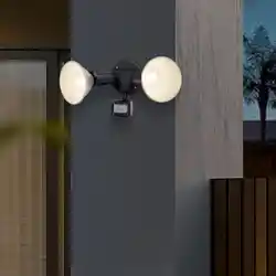
Model Number: E8972W
E8972BZ
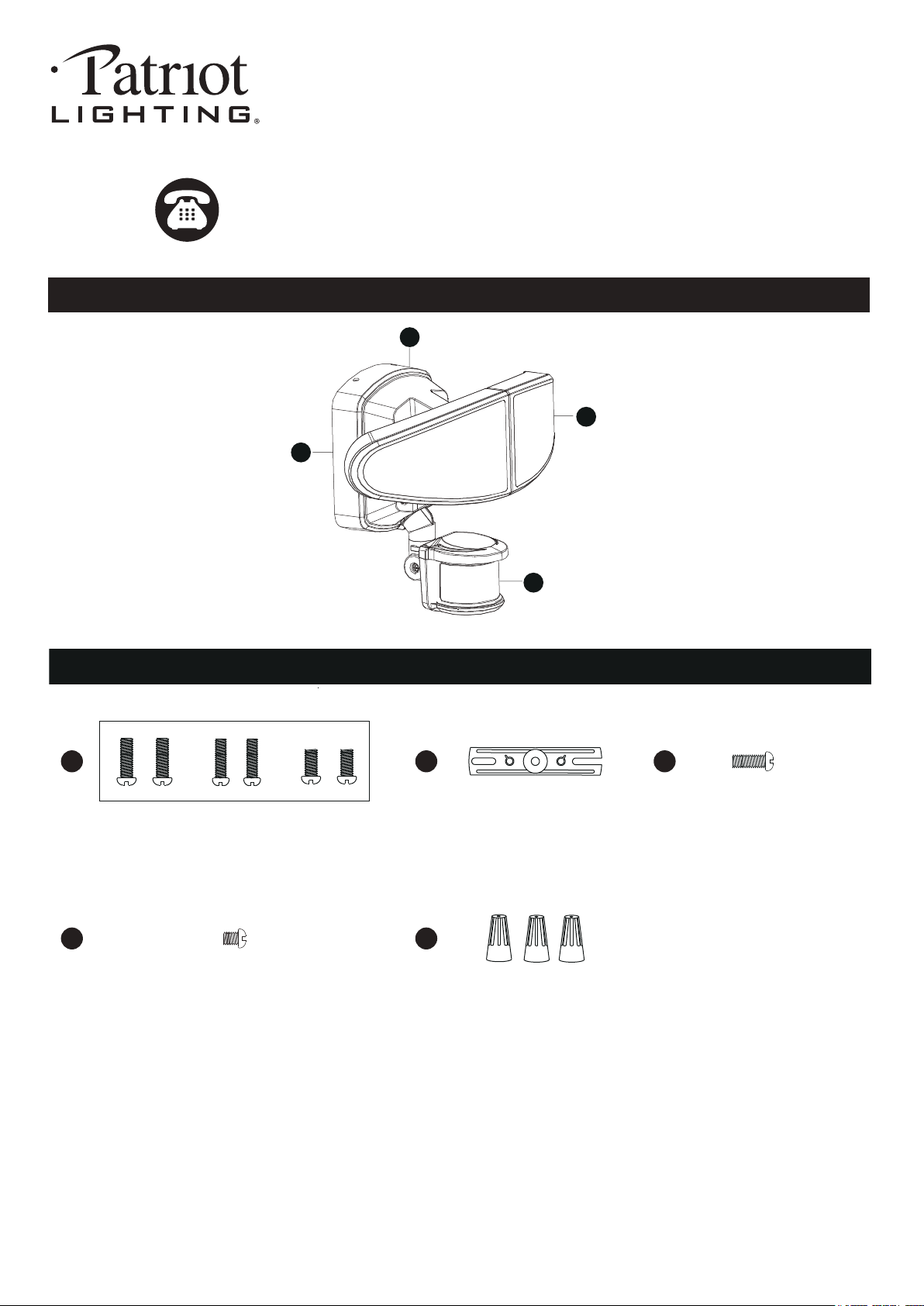
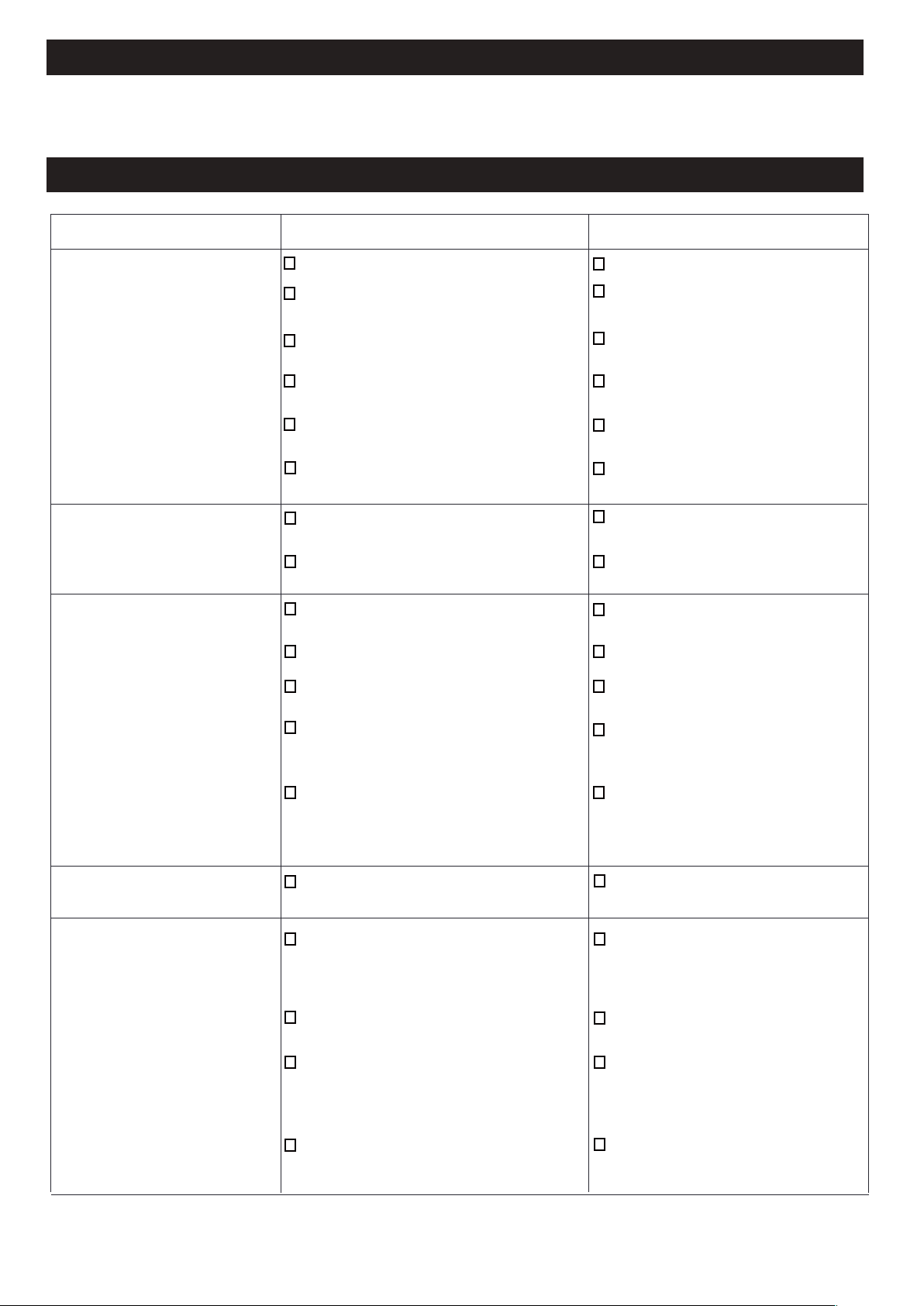
A
C
B
D
Mounting Bracket Screw
X1
200810
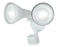
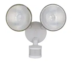
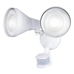
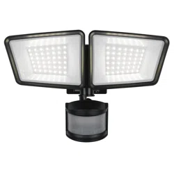
2-LIGHT OUTDOOR SENSOR LIGHT
AA BB
DD EE
CC
HARDWARE CONTENTS Note: Hardware not shown actual size.
Mounting Screw
X2
Wire Connector
X3
Mounting Strap
X1
PACKAGE CONTENTS
Fixture Mounting Screw
X1
Before beginning assembly, installation or operation of product, make sure all parts are present. Compare parts with
package contents list and diagram on previous page. If any part is missing or damaged, do not attempt to assemble,
install or operate the product. Contact customer service for replacement parts.
Tools Required for Assembly (not included): Screwdriver, Phillips Screwdriver, Pliers, Electrical Tape, Wire Cutters,
Safety Glasses, Ladder,wire stripper.
Page 2 of 8
SAFETY INFORMATION
PREPARATION
Important to know
200810
ASSEMBLY INSTRUCTIONS
1. This fixture requires a 120 VAC, 60 Hz power source.
2. For general safety and to avoid any possible damage to the sensor, be sure the power is switched "off" before
adjustment.
3. Motion sensor: turns light ON automatically when motion is detected and turns light OFF automatically when motion
stops.
4. Photocell keeps the light OFF during daylight hours.
• All electrical connections must be in agreement with local codes, ordinances or the national electric code (NEC).
Contact your municipal building department to learn about your local codes, permits and/or inspections.
• Risk of fire – most dwellings built before 1985 have supply wire rated for 140°F/60ºC. Consult a qualified electrician
before installation
• Do not connect this fixture to an electrical system that does not provide a means for equipment grounding. Never use
a fixture in a two-wire system that is not grounded. If you are not sure your lighting system has a grounding means, do
not attempt to install this fixture. Contact a qualified, licensed electrician for information with regards to proper
grounding methods as required by the local electrical code in your area.
Please read and understand this entire manual before attempting to assemble, operate or install the product.
WARNING
•
Turn off electricity at main fuse box (or circuit breaker box) before beginning installation by removing fuse (or switching
off circuit breaker).
• Be careful not to damage or cut the wire insulation (covering) during fixture installation. Do not permit wires to contact
any surface having a sharp edge. To do so may damage or cut the wire insulation, which could cause serious injury
or death from electric shock.
NOTICE: Do not connect this light fixture to a dimmer switch or timer.
CAUTION
Maximum Wattage: 35W
Work Temperature: -4°F~113°F
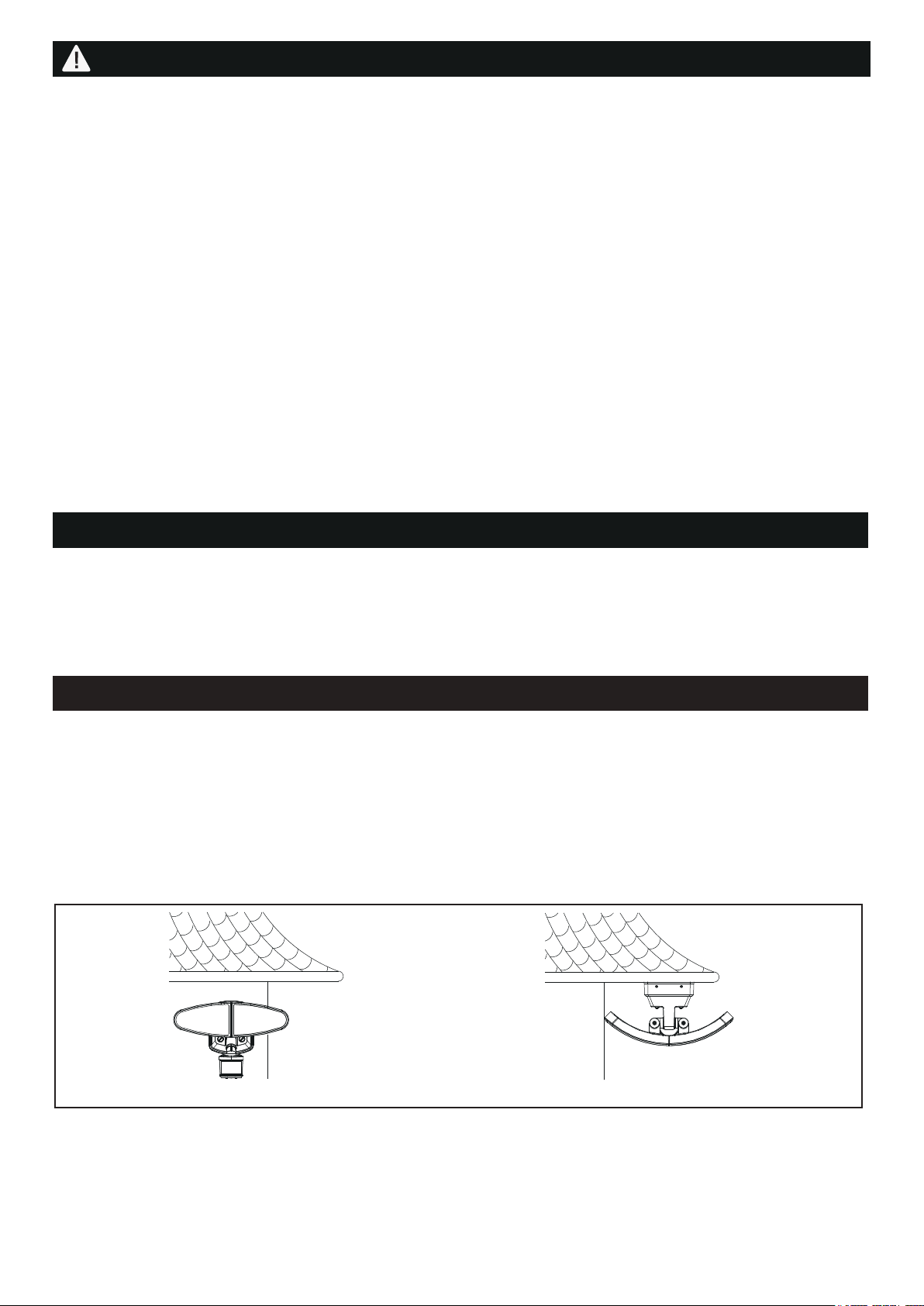
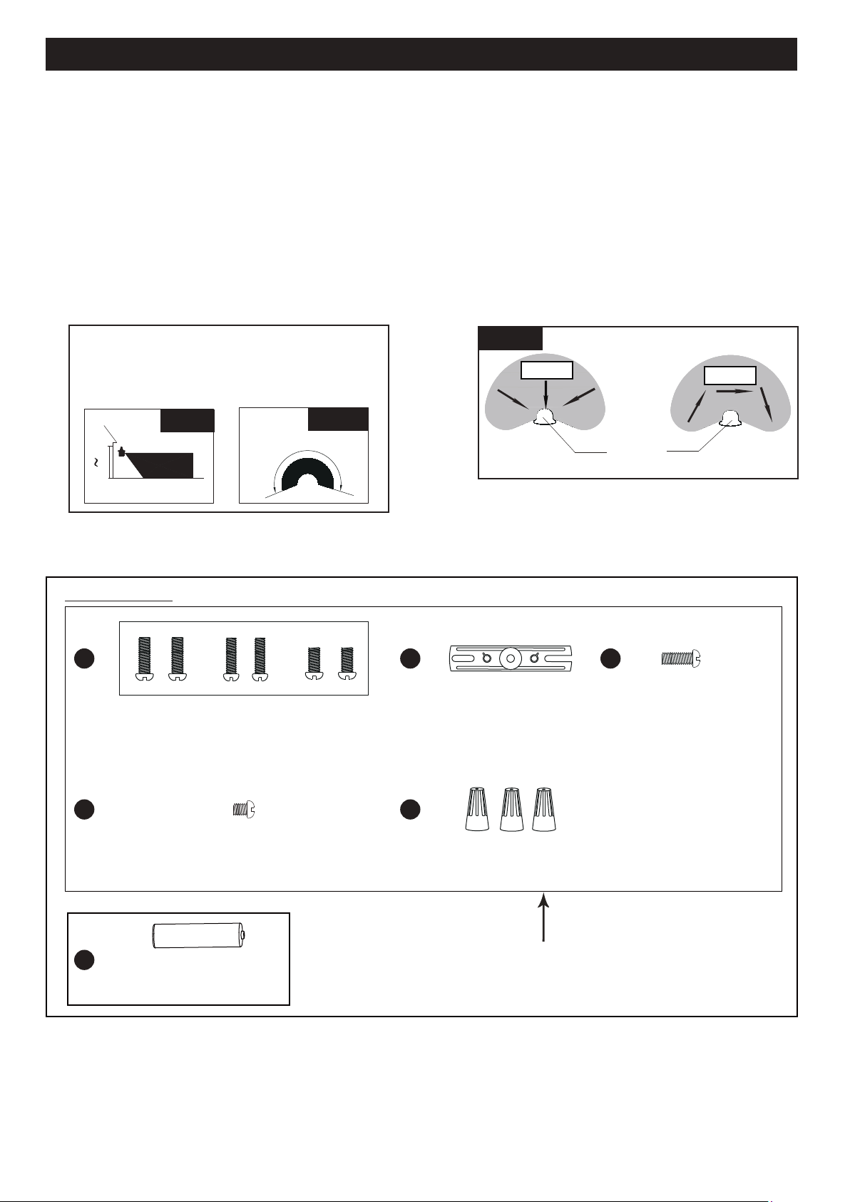
Note: Fixture can be wall mounted or eave mounted.
Wall Mounted
Eave Mounted
Read notes section on page 5 for additional information about mounting location of fixture.
Light fixture and sensor should be mounted as shown above when installed (depending upon type of installation).
Page 3 of 8
ASSEMBLY INSTRUCTIONS (continued)
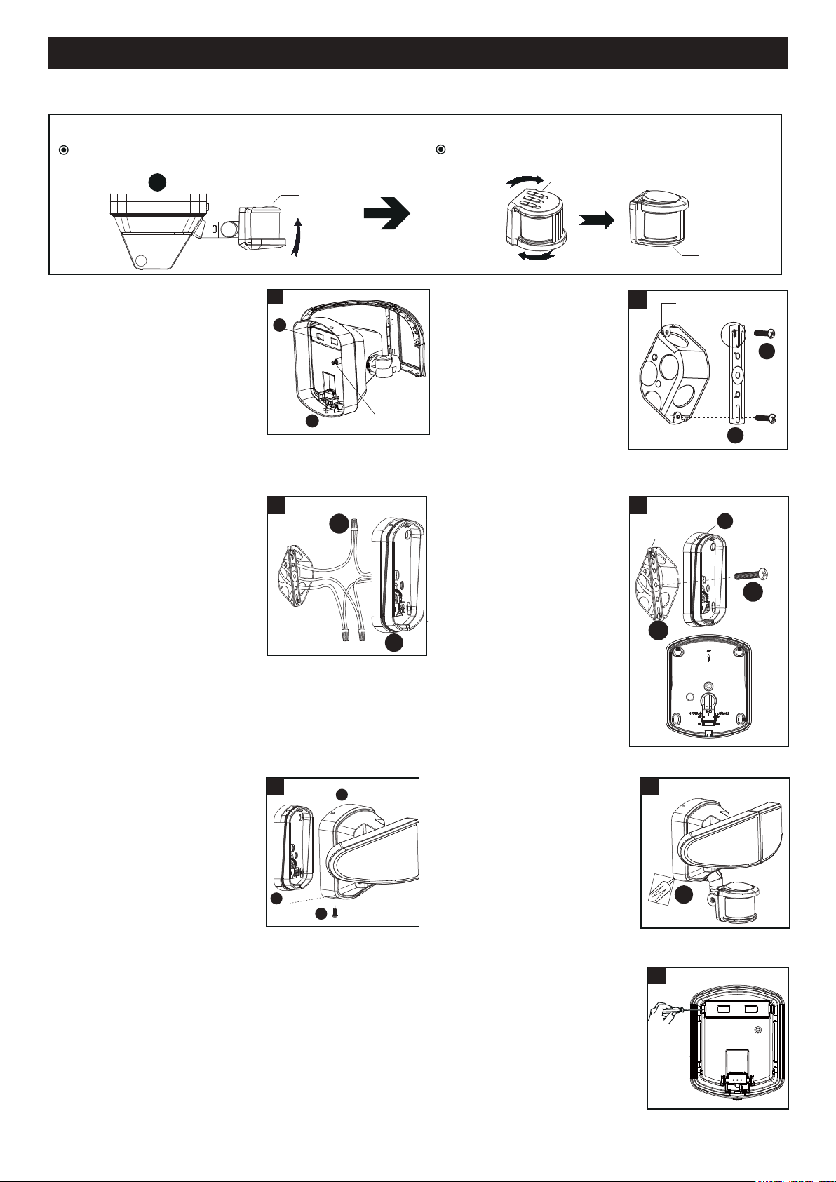
2. Install the mounting strap
(BB) to the outlet box with
the stamped word “FRONT”
facing away from the outlet
box, using two mounting
screws (AA) that best fit the
outlet box. Backplate should
sit flush against wall surface
when secured. (Choose one
matching pair of suitable
mounting screws (AA) from the 3 pairs provided)
3. Pull out the source wires from
the outlet box. Make wire
connections using wire
connectors (EE) as follows:
---Connect the black wire from
the fixture to the “hot” wire
from the power source
(usually black).
---Connect the white wire from
the fixture to the neutral wire
from the power source (usually white).
---Connect the grounding wire from the fixture to the
grounding wire from the power source (usually
green / yellow insulation).
Carefully tuck the wires back into the outlet box.
1. Before installing, please ensure
the back up battery (FF) is
working and can turn the light
on by press the switch on the
light fixture (B).
200810
Before installing the light fixture under an eave, the sensor head must be rotated as shown in the next two steps for
proper operation and to avoid the risk of electrical shock.
Outlet Box
2
BB
AA
4. Place mounting bracket (A)
against the outlet box, insert
the mounting bracket screw
(CC) through the mounting
bracket hole, thread
mounting bracket screw
(CC) into the center hole of
the mounting strap (BB).
Tighten the mounting
bracket screw (CC) securely.
▲ When mounting to a wall,
the “UP” arrow must point
upward.
▲ When mounting to an
eave, the “UP” arrow
must point toward the building.
A
For eave mounted only:
Swing the sensor head towards the mounting bracket.
Rotate the sensor head clockwise 180˚ so the
controls face down.
Controls
Controls
Controls
Outlet Box
A
CC
4
BB
5. Attach the light fixture (B) to the
mounting bracket (A), secure it
with the fixture mounting screw
(DD). The hole on the upper
end should correspond to the
scale and can be pressed down.
NOTE: Three needles should
be inserted into three holes.
6. With silicone caulking
compound, caulk completely
around where the mounting
bracket (A) meets the wall
surface.
CAUTION: Be sure to caulk
completely where the
mounting bracket (A) meets
the wall surface to prevent
water from seeping into the outlet box.
7. Replacing Battery Steps
Remove the battery cover from the fixture by screwdriver and replace the old battery
with a new battery 7182BB, then restore the battery cover back.
5
B
DD
A
Switch
1
FF
B
6
A
Outlet Box
EE
A
3
7
Page 4 of 8
ASSEMBLY INSTRUCTIONS (continued)
ASSEMBLY INSTRUCTIONS (continued)
D
200810
Sensor Adjustment Lower For Short Coverage
Sensor Adjustment Higher For Long Coverage
Fig. 4
Fig. 2
Fig. 3
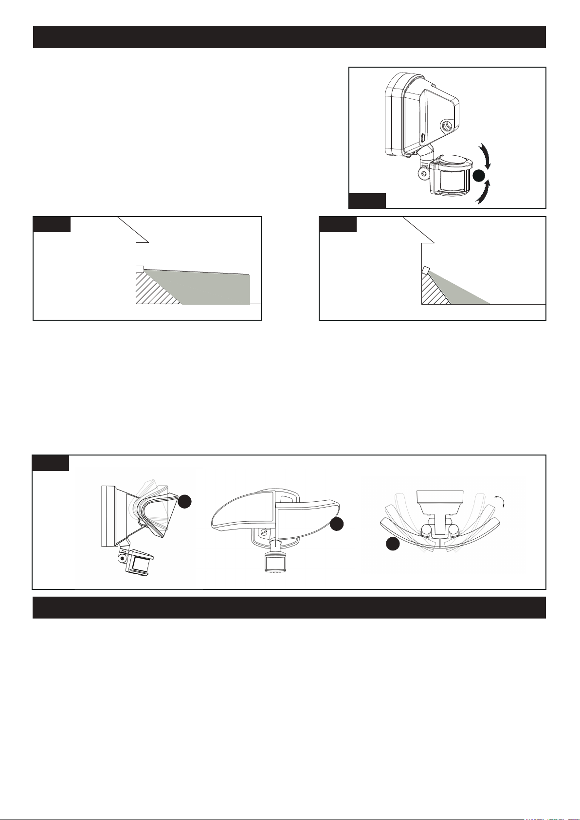
Adjusting the Light Head (C):
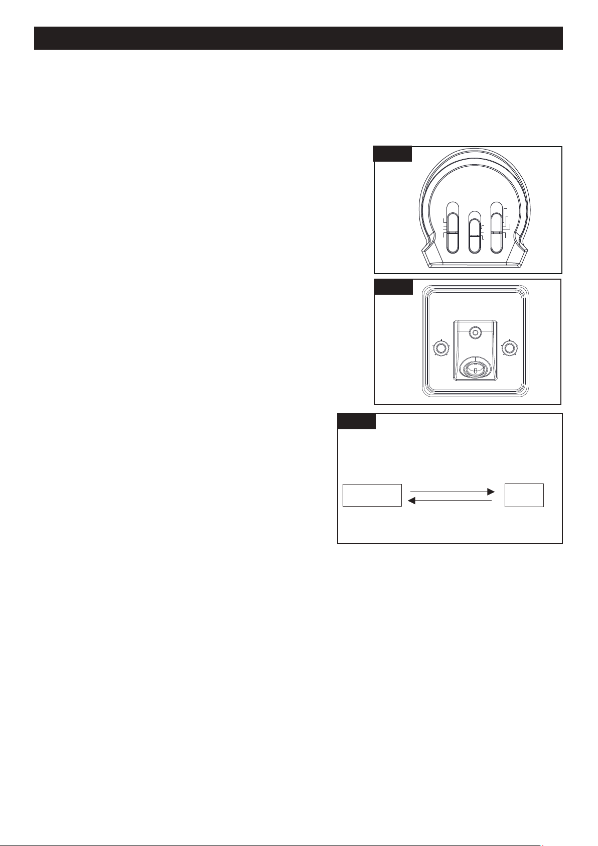
Sensitivity of Motion Sensor
● You can adjust the sensitivity of the motion sensor by using the “SENSITIVITY” selector located on the middle of
the bottom surface of the sensor. (See Fig. 5)
● Adjust motion sensor sensitivity to HIGH (H), MEDIUM (M), or LOW (L) to achieve desired performance.
● Approximate range for each setting: 70 ft. (H), 45 ft. (M), 20 ft. (L).
Adjusting the Sensor Head (D):
1. Aim sensor head toward desired detection area, maintaining a
5° - 40° downward angle to allow moisture to drain.
Note: Make sure sensor head is positioned with controls facing
toward the ground.
Fig. 1
1. Adjust the light head up or down, left or right for desired area. Keep the light heads at least 1˝ (25mm) away from
the sensor.(See Fig. 4)
2. Keep the light heads (C) 30˚ below horizontal to avoid water damage and electrical shock.
2. You can rotate the sensor head up and down to change the coverage
area. (See Fig. 1)
Note: Range set too high may increase false triggering.
(See Fig. 2 and Fig. 3)
Choose a mode by sliding the switch on the bottom of the sensor. (See Fig.5)
Note: When power is first applied, the light will be on and warm up lasts 30 seconds.
1. Test mode (daytime or nighttime operation )
● Set the time switch to the “TEST” position. (See Fig.5)
● With the power on, the light turns to low-level brightness automatically.
● The light turns to high-level brightness when motion is detected, and stays on as long as the motion continues.
Then it reverts back to low-level brightness about 5 seconds after motion is no longer detected.
Note: You can adjust the low-level (0~50%) and high-level (50~100%) brightness by using the brightness
switch on the backplate. (See Fig. 6)
C
C
C
ASSEMBLY INSTRUCTIONS (continued)
ASSEMBLY INSTRUCTIONS (continued)
ASSEMBLY INSTRUCTIONS (continued)
FUNCTION AND OPERATION
Page 5 of 8
ASSEMBLY INSTRUCTIONS (continued)
ASSEMBLY INSTRUCTIONS (continued)
200810
2. AUTO MODE (nighttime operation only)
● To shift to “AUTO” mode, slide the Time Delay switch to the desired time setting (1min, 2min,3 min). At dusk, the
light turns on to pre-selected low level brightness. When motion is detected, the light turns to full brightness and
stays on as long as motion continues. When the motion is no longer detected, the light at full brightness remains
on for the predetermined time you set (1min, 2min,3 min), and then switches back to low level automatically.
● The light turns off automatically at dawn.
Note: You can adjust the low-level (0~50%) and high-level (50~100%)
brightness by using the low-level (0~50%) and high-level
(50~100%) brightness knob. (See Fig. 6)
3 HOURS (3H) MODE (nighttime operation only)
● The light turns to high-level brightness (100%) at dusk, and stays "ON"
for 3 hours. Then it turns to low-level brightness. It turns to high-level
brightness (100%) when motion is detected, and stays on as long as
motion continues. When motion is no longer detected, it remains on for
the predetermined shut-off delay time you set (1min, 2min,3 min), and
then returns to the predetermined low-level brightness automatically.
● The light turns off automatically at dawn.
Note: You can adjust the low-level (0~50%) and high-level (50~100%)
brightness by using the low-level (0~50%) and high-level
(50~100%) brightness knob. (See Fig. 6)
4. 6 HOURS (6H) MODE (nighttime operation only)
● The light turns to high-level brightness (100%) at dusk, and stays "ON"
for 6 hours. Then it turns to low-level brightness. It turns to high-level
brightness (100%) when motion is detected, and stays on as long as
motion continues. When motion is no longer detected, it remains on for
the predetermined shut-off delay time you set (1min, 2min,3 min), and
then returns to the predetermined low-level brightness automatically.
● The light turns off automatically at dawn.
Note: You can adjust the low-level (0~50%) and high-level
(50~100%) brightness by using the low-level (0~50%)
and high-level (50~100%) brightness knob. (See Fig. 6)
5. PHOTOCELL (PC) MODE (nighttime operation only)
● The light turns on at full brightness at dusk and remains
on until dawn.
Note: You can adjust the high level brightness (50%~100%)
by using the high level brightness knob. (See Fig. 6)
6. Manual Override (nighttime operation only)
● To temporarily override the settings in “AUTO”, “3H” or “6H”
modes for on-demand continuous full-brightness at night,
turn the wall switch “OFF” then turn it “ON” twice within 3
seconds. The light remains on all night long. To shift back
to “AUTO”, “3H” or “6H” mode, turn the wall switch “OFF”
then turn it “ON” twice within 3 seconds again.
● The light turns off automatically at dawn.
7. Emergency Backup (nighttime operation only)
● Emergency backup works when AC power failure, the light lasts on 30
seconds and then enters the AUTO mode, When motion is detected ,the
light turns on at 400lm brightness,the light remains on for predetermined
shut-off delay time you set (1min ,2min,3min),and then turns off.
When AC power supply recovery, the light warm up 30 seconds and
then restore the previous function you set.
Note: To make sure the above functions operate properly, always keep the wall switch in
the “ON” position (including the daytime).
LOW LEVEL
HIGH LEVEL
25%
0
50%
75%
50%
100%
FUNCTION AND OPERATION (continued)
Fig. 5
Fig. 6
“AUTO” “3H”
or “6H” Mode
Manual
Override
Manual Override Operation Diagram
Turn wall switch OFF-ON
-OFF-ON in 0.5~3 Seconds
Turn wall switch OFF-ON
-OFF-ON in 0.5~3 Seconds
Fig. 7
MODE
SENSITIVITY
TIME
L
M
H
6H
AUTO
3H
PC
TEST
1MIN
2MIN
3MIN
Page 6 of 8
ASSEMBLY INSTRUCTIONS (continued)
ASSEMBLY INSTRUCTIONS (continued)
200810
The following parts are available for reorder if damaged or missing. Call our toll free at 1-800-887-6326.
Battery
7182BB
FUNCTION AND OPERATION (continued)
Fig. 11
Motion
Least sensitive
Motion
Most sensitive
Sensor
20'
8.0'
12.0'
70'
Be sure the light is mounted straight on the wall
or eave; otherwise, the detection distance may
be limited.
Fig. 9
Fig.10
240'
Assembly Kit
5327MM (1 SET)
Spare Parts List:
Customization Options
Shut-off Delay
● The shut-off delay is the length of time the light will stay at full brightness after motion is detected.
● You can set the shut-off delay time: “1min”, “2min”, “3min”.
Notes:
1. The sensitivity of the motion sensor will increase as the environmental temperature gets cooler. For best
performance, gently clean the lens with a soft cloth every 1 or 2 months to ensure maximum sensitivity.
2. For best performance, install fixture at least 8 feet above the ground. At such a height, the fixture will provide a
detection distance of up to 70 feet at 77 degrees Fahrenheit. (See Fig.9)
3. The sensor detects movement across a detection range of 240 degrees. (See Fig.10)
4. The sensor will be more sensitive to motion across its detection path than motion directly towards it. (See Fig.11)
5. To reduce possible nuisances, do not mount the fixture near a heat source like an air conditioner, vent or furnace
exhaust, or in a direction facing any reflective object or other nearby light source.
Mounting Bracket Screw
X1
AA BB
DD
FF
EE
CC
Mounting Screw
X2
Wire Connector
X3
Mounting Strap
X1
Fixture Mounting Screw
X1
Page 7 of 8
TROUBLE SHOOTING
CARE AND MAINTENANCE
Clean the glass and coated metal surfaces with a non-abrasive cleaner. Do not use any cleaners with chemicals,
solvents or harsh abrasives, The motion detecting lens is coated with a specially painted finish and requires special
care when cleaning. Use only a soft dry cloth to dust or wipe the lens area.
200810
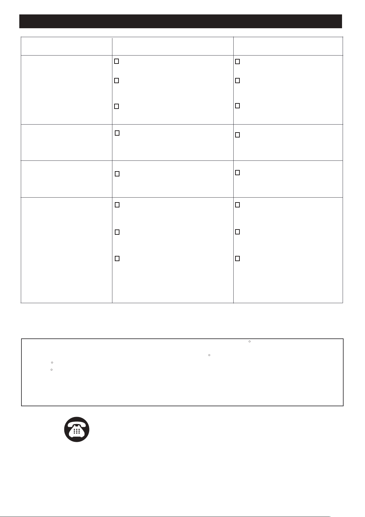
Problem
The light will not come on.
The light comes on during the
day.
The light comes on for no
apparent reason.
The light turns off too late in
the PC setting.
The light stays on continuously.
The light fixture may be installed in a
relatively dark location.
Relocate the light fixture setting.
The light switch is turned off.
Possible Cause Solution
The fuse is blown or the circuit
breaker is turned off.
Turn the light switch on.
Replace the fuse or turn the circuit
breaker on.
Recheck after dark.
Verify the wiring is correct.
Re-aim the motion sensor to cover
the desired area.
Increase the “SENSITIVITY” setting.
Daylight turn-off (photocell) is in
effect.
The circuit wiring is incorrect (if this
is a new installation).
The motion sensor is aimed in the
wrong direction.
The outside air temperature is close
to the same as a person’s body heat.
The motion sensor may be installed in
a relatively dark location.
The light fixture is operating
normally under these circumstances
Set the “TIME” switch to the 1min.
2min.3min setting.
The “TIME” switch is in the “TEST”
position.
The motion sensor may be sensing
small animals or automobile traffic.
Decrease the “SENSITIVITY” setting
or reposition the motion sensor.
Decrease the “SENSITIVITY” setting.
The light fixture is operating normally
under these circumstances.
Decrease the “SENSITIVITY” setting.
Do not use a dimmer or timer to
control the light fixture. Replace the
dimmer or timer with a standard
on/off wall switch.
The “SENSITIVITY” switch is set too high.
The “MODE” switch is in the 3 hour and 6
hour, or PC setting.
The outside temperature is much
warmer or cooler than a person’s body
heat (summer or winter).
The light fixture is wired through a
dimmer or timer.
The motion sensor may be picking up
a heat source, such as an air vent,
dryer vent, or brightly painted,
heat-reflective surface.
Decrease the “SENSITIVITY” setting
or reposition the motion sensor.
Switch the motion sensor to auto.
See Using manual mode on page 5.
Do not use a dimmer or timer to
control the light fixture. Replace the
dimmer or timer with a standard
on/off wall switch.
Install the light fixture on a circuit
without motors, transformers, or
fluorescent bulbs.
The motion sensor is in manual mode.
The light fixture is wired through a
dimmer or timer.
The light fixture is on the same circuit
as a motor, transformer, or fluorescent
bulb.
Page 8 of 8
200810
FIVE-YEAR LIMITED WARRANTY: If, during normal use, this PATRIOT LIGHTING lighting fixture breaks or fails due
to a defect in material workmanship within five (5) years from the date of original purchase, simply bring this lighting
fixture with the original sales receipt back to your nearest MENARDS retail store. At its discretion, PATRIOT
LIGHTING agrees to have the product or any defective part(s) repaired or replaced with the same or similar PATRIOT
LIGHTING product or part free of charge, within the stated warranty period, when returned by the original purchaser
with original sales receipt. This warranty; (1) excludes expendable parts including but not limited to light bulbs; (2) does
not cover damage that has resulted from abuse or misuse; and (3) does not cover any losses, labor, injuries to
persons/property or costs. This warranty does give you specific legal rights and you may have other rights, which vary
from state to state.
Questions, problems, missing parts?
Before returning to your retailer, call our customer service at 1-800-887-6326
Monday – Friday 9:00 a.m. – 5:00 p.m. CST
R
R
R
R
If unable to fix any of the above issues, please consult a certified electrician.
The light flashes once then
stay off in manual mode.
The light is very dim and goes
off quickly after motion has
stopped.
Light will not come on when
power is turned off.
The light is in battery backup mode.
The light flashes on and off.
Problem Possible Cause Solution
The motion sensor is detecting light from
the lamp heads.
Reposition the lamp heads to keep
the
area below the motion sensor
relatively dark.
Ensure power is turned on at the
light switch. Light will operate
normally once the power is back on.
Heat or light from the lamp heads may
be turning the motion sensor on and off.
Heat is being reflected from other objects
and may be turning the motion sensor on
and off.
The motion sensor is in “TEST” mode
and warming up.
Reposition the lamp heads away
from the motion sensor.
Decrease the “SENSITIVITY” setting
or reposition the motion sensor.
While in “TEST” mode, the light only
stays on for 5 seconds. Set the
“TIME” switch to 1min.2min.3min
The outside temperature is either too
hot or cold for the lithium battery to
operate safely.
The lithium battery charge is too low.
The lithium battery is no longer able to
hold a charge.
When the outside temperature is in
a safe range the lithium battery will
work correctly. power is back on.
When the lithium battery has been
charged to a safe level, the light will
work correctly.
If the battery will not charge after 7
days (with the light switch in the ON
position), then replace the battery
with a Li-ion, 18650-2000mAh, 3.7V
7.4wh battery with the correct
connector.
TROUBLE SHOOTING (CONTINUED)