Installation Manual
CS1 is ready to make your home energy efficient and more
comfortable. Follow these easy steps to get started.
LUX Products offers installation and product videos
Please visit LuxProducts.com/videos or visit our YouTube
channel LUX Products Corporation. To contact LUX
Technical Support, please call 856.234.8803.
For more information about installation settings, please visit
LuxProducts.com/CS1manual
Para ver estas instrucciones en español, por favor visite
LuxProducts.com/CS1manualsSP
This manual is a comprehensive guide to installation and wiring.
LuxProducts.com | 3
Table of Contents
1. Start Here ......................................................................................... 2-5
2. Installing with a C-Wire ..............................................................6-9
3. Installing with Power Wire (Included) ............................. 10-13
4. Installing with LUX Power Bridge (Not Included) ..... 14-17
5. HVAC System Setup ................................................................. 18-21
6. Connecting to the Network ................................................ 22-25
7. Appendix ......................................................................................26-31
1. START HERE
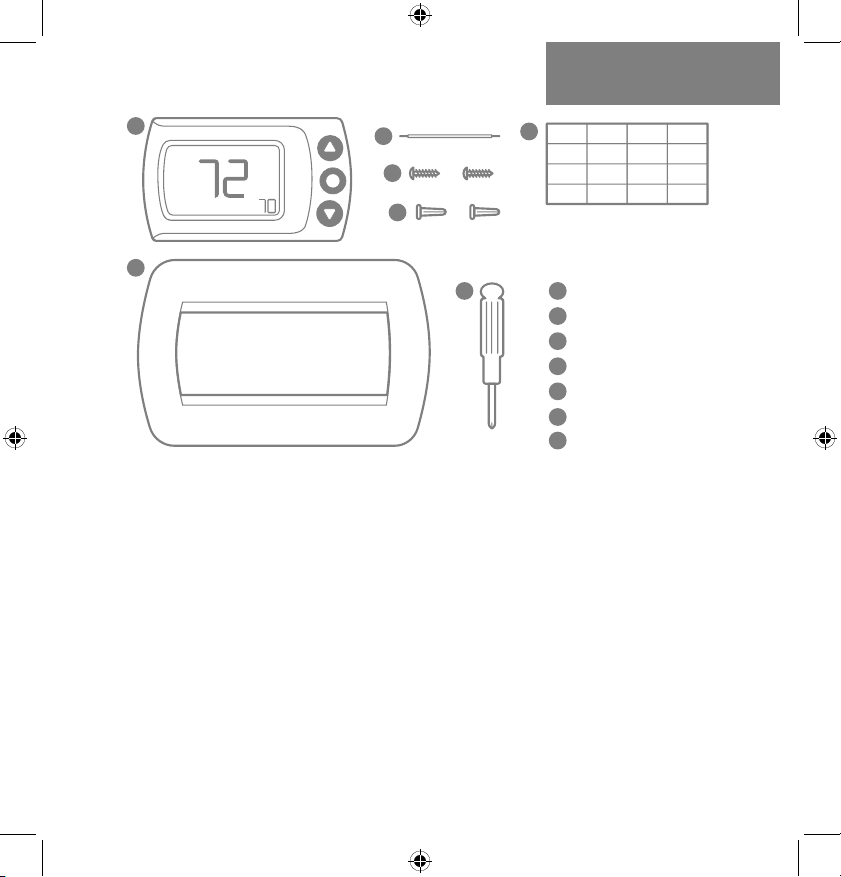
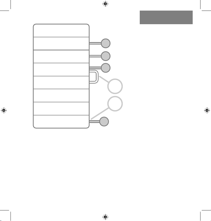
INSIDE THE BOX:
CS1 Thermostat
Power Wire
Mounting Screws
Wall Anchors
Wire Labels
Wall Plate
Screwdriver
1
2
3
4
5
6
7
1
2
3
4
5
6
7
Required Tools:
-Phillips Screwdriver -Smartphone
Optional Tools:
-Power Drill -Wire Stripper
4 | 856.234.8803
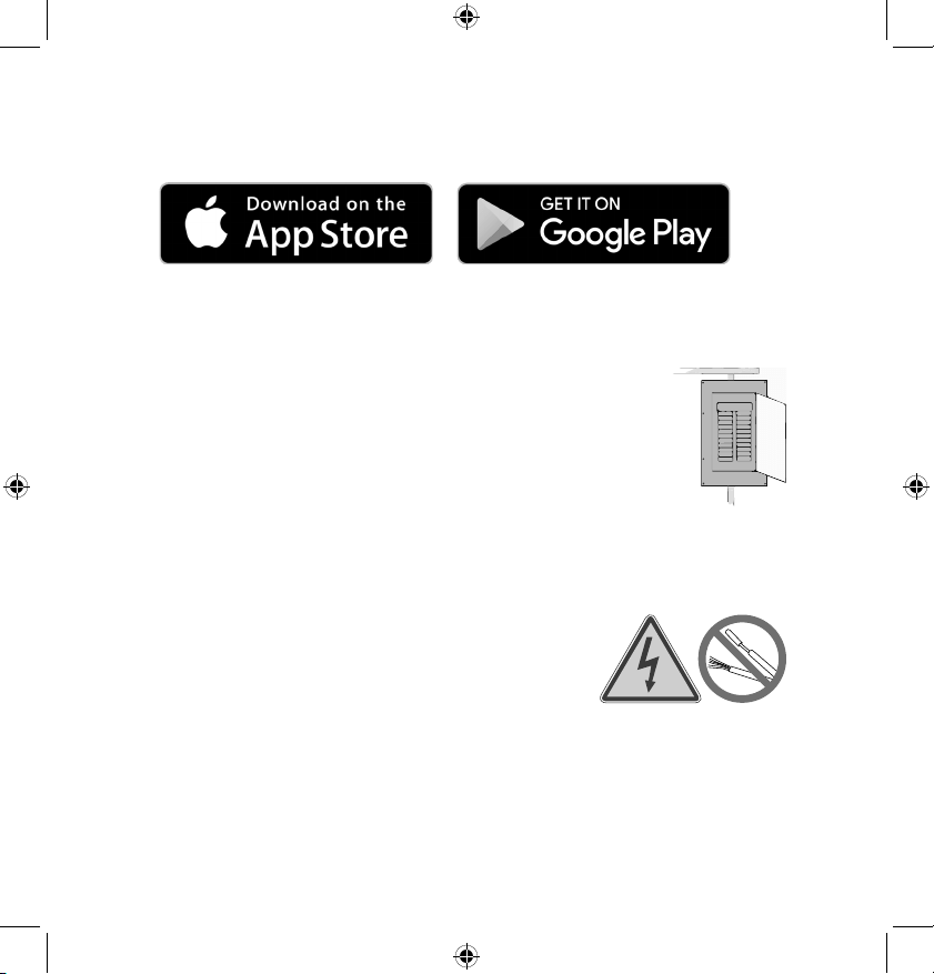
Step 1.1: Download the LUX Products App to your mobile
device and create an account.
Step 1.2: Now set your phone aside and turn off the power at
the circuit breaker to both your heating and cooling systems
before performing any wiring.
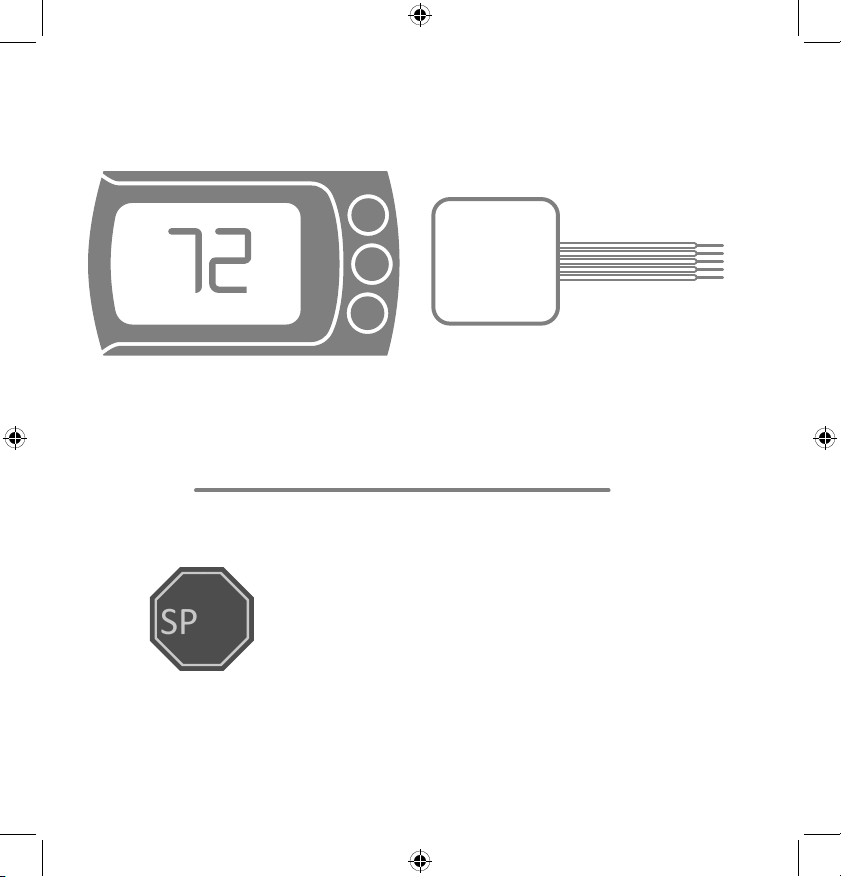
Step 1.3: Confirm that your heating and cooling
system is powered down by changing the
temperature on your thermostat.
Hint: Your system should not make any noise and
you should not feel any air exiting your vents.
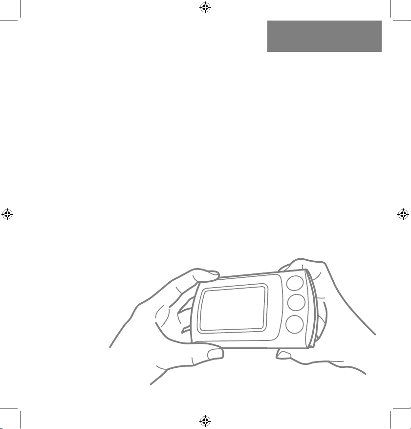
Step 1.4: Remove the front of your old thermostat from its
base. If you see thick black wires, wire nuts,
or any labels that say 120-240VAC or High
Voltage, your system is not compatible
with CS1. Please call LUX Technical Support
at 856.234.8803 before proceeding with
your installation. If you do not see any high
voltage labels or wires, you can continue
with your installation.
HIGH
VOLTAGE
LuxProducts.com | 5
1. START HERE
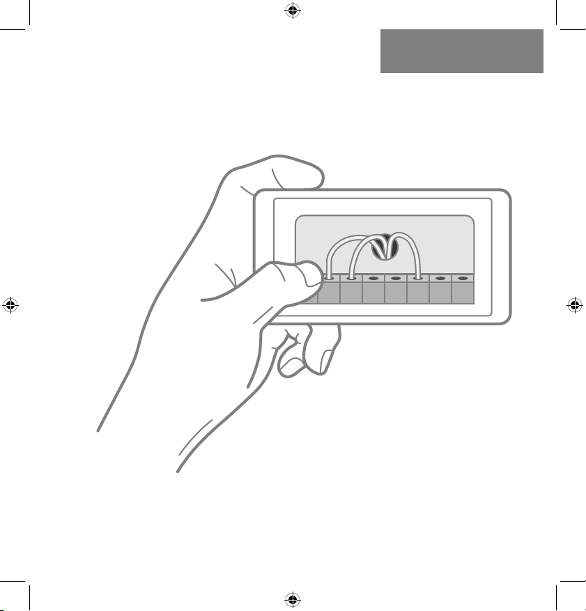
Step 1.5: Use the included wire labels to mark which wire is
connected to each terminal in your old thermostat.
Take a picture of your current wiring layout,
you will need this picture later.
Step 1.6: Confirm that you have a C-Wire. If you do, please turn
to the next page. If you do not, please skip ahead to page 10.
1 1 1
NOTE: If you have any wires at
your thermostat that are not coming
from the wall, please leave those wires
in your old thermostat. They are not
needed for installing your CS1.
6 | 856.234.8803
Installing with a C-wire
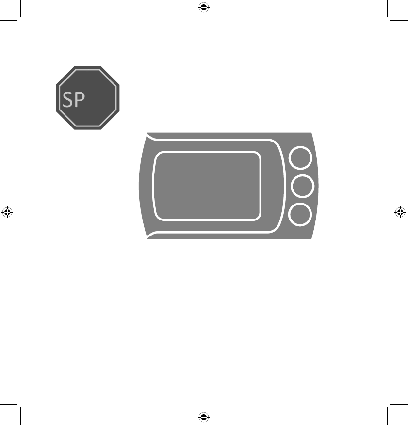
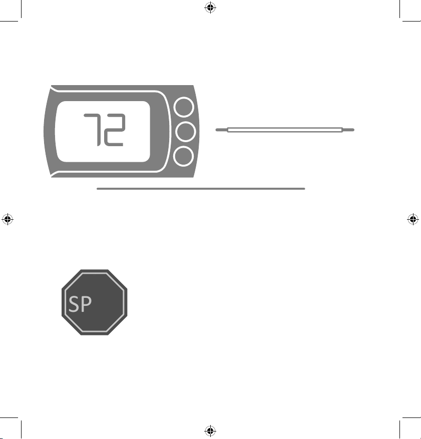
Before starting
Turn off the power at the circuit breaker
to both your heating and cooling systems
before performing any wiring.
STOP
Step 2.1: Identify your system configuration (see wiring
diagrams in appendix). Potential configurations include:
• Conventional 1H/1C (Y, G, W, R, C)
• Conventional 2H/1C (Y, G, W, W2, R, C)
• Heat Pump Single-Stage (Y, G, R, O/B, C)
• Heat Pump with auxiliary heat or dual fuel (Y, G, R, O/B, W, C)
If you have only one R wire, please use the RH terminal. If
you have a different configuration other than what is listed
above, please call LUX Technical Support for help with your
installation.
LuxProducts.com | 7
INSTALLATION WITH
C-WIRE2.
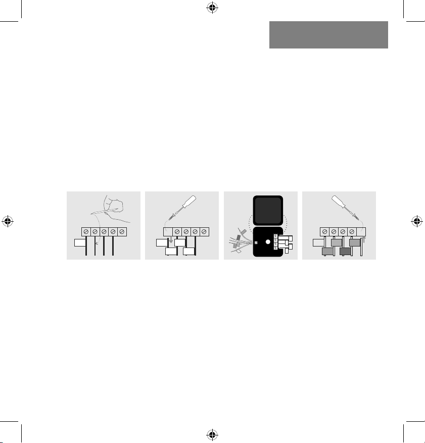
Step 2.2: Remove each wire from its terminal – make sure
that they don’t fall down back into the wall.
Step 2.3: Remove the mounting screws from the base of the
old thermostat. Remove the base from the wall.
Step 2.4: If you would like to use the trim plate or wall
anchors, you can install them now.
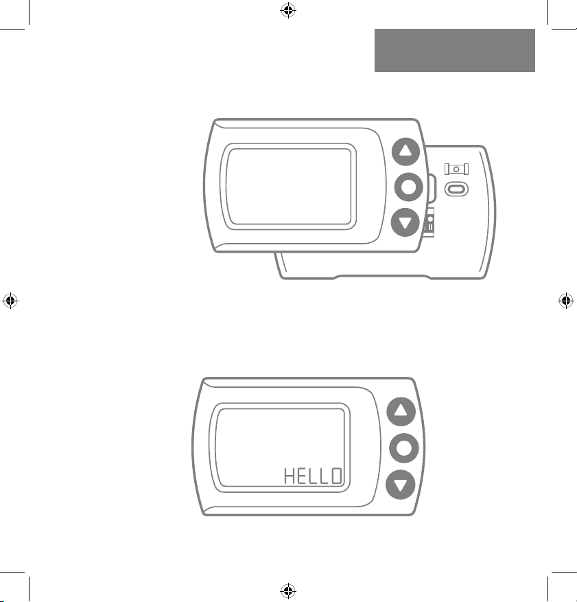
Step 2.5: Separate CS1 from its base, pull the halves apart
from the bottom edge. Pull the wires from your wall through
the center hole of the CS1 base. Secure the base to the wall
using the included mounting hardware.
8 | 856.234.8803
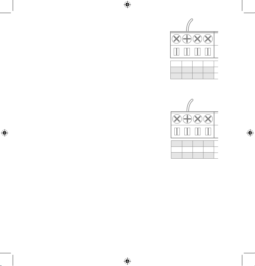
Option 1 - Conventional (furnace) Systems:
Step 2.6(f): Following the terminal labels
marked “Conventional” on the thermostat
base, loosen the screw and insert each
labeled wire into the top hole of the
corresponding terminal, tighten the screw.
Step 2.7(f): If you have both an RC and RH wire present,
then remove the red cap located on the left side of the
terminal pins. You can now skip ahead to step 2.8.
Option 2 - Heat Pump Systems:
Step 2.6(hp): Following the terminal labels
marked “Heat Pump” on the thermostat base
and referencing your wiring photo, loosen the
screw and insert each labeled wire into the top
hole of the corresponding terminal, tighten the
screw.
If your old thermostat did not have a W1 wire but did have a
W2 wire, please insert the W2 wire into the W1 terminal.
Step 2.7(hp): If you have both an O wire and a B wire
(i.e. in some systems), please install the B wire to the “C”
terminal.
For more detailed directions, please see the wiring diagrams
in the appendix or call LUX Technical Support.
C
C
W1
W1
W2
O/B
1 4 2
C
C
W1
W1
W2
O/B
1 4 2
LuxProducts.com | 9
Installation with C-wire
Step 2.8:
Securely fasten CS1 onto its base. Once it has
clicked into place, return power to your heating and
cooling system.
Step 2.9: After your thermostat powers up, you are ready
to configure CS1 for your heating and cooling system and
connect to a wireless network.
Please skip ahead to the “System Setup” section of this
manual on page 18.
INSTALLATION WITH
C-WIRE2.
10 | 856.234.8803
Installing without a C-Wire
Using the LUX Power Wire (included)
Before starting
Turn off the power at the circuit breaker
to both your heating and cooling
systems before performing any wiring.
STOP
1. Install and wire CS1
2. Install LUX Power Wire
(at your furnace)
For installation without C-wire,
you will need to access your furnace.
NOTE: DO NOT USE P-WIRE IF YOU HAVE
AN ELECTRIC FURNACE OR HEAT PUMP
Installation without C-wire
Hint: helpful videos showing how to wire a thermostat with
the LUX Power Wire are available at:
LuxProducts.com/videos

LuxProducts.com | 11
INSTALLATION WITH
P-WIRE3.
Step 3.1: Starting at your thermostat,
confirm that you have one of the system configurations below:
• Conventional 1H/1C (Y, G, W, R)
• Conventional 2H/1C (Y, G, W1, W2, R)
If you have a different configuration other than what is listed
above or if you have an electric furnace, please call LUX
Technical Support for help with your installation.
Step 3.2: Remove each wire from its terminal – make sure
that they do not fall down back into the wall.
Step 3.3: Remove the mounting screws from the base of the
old thermostat. Remove the base from the wall.
Step 3.4: If you would like to use the trim plate or wall
anchors, you can install them now.
Step 3.5:
Separate CS1 from its base, pull the halves apart from
the bottom edge. Pull the wires from your wall through the
center hole of the CS1 base. Secure the base
to the wall using the
included mounting
hardware
.
12 | 856.234.8803
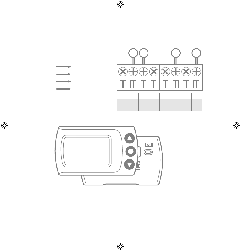
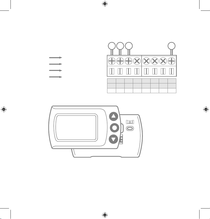
Step 3.6: Following the terminal labels marked “Conventional”
on the thermostat base, loosen the screw and insert each
labeled wire into the top hole of the corresponding terminal.
Connect as follows:
Step 3.7: Securely fasten CS1 onto its base
Step 3.8: Go to your furnace – remove the door or panel
and locate your control board or transformer. In most cases,
there should be four wires running from the furnace to your
thermostat – Y, G, W, and R. If you have additional wires, leave
them as is.
Y1 Terminal
W1 Terminal
RH Terminal
C Terminal
Y Wire
W Wire
R Wire
G Wire
C
C
W1
W1
W2
O/B
1 4 2
Y1
Y1
RC
RC
RH
RH
G
G
3
Y
G
W R
NOTE: The G wire was previously
in the G terminal, it will now go to
the C Terminal on CS1.
LuxProducts.com | 13
INSTALLATION WITH
P-WIRE3.
Step 3.10: If you had to remove a panel or door to access
your control panel, replace it now.
Step 3.11: Return power to your heating and cooling
system. If your system, including your thermostat, does not
power up please call LUX Technical Support.
After CS1 powers up, you are ready to configure it for your
heating and cooling system (page 21).
Step 3.9:
A) Remove the G
Wire from the Fan
Terminal at your
furnace, insert
the wire into your
Furnace Transformer
Terminal
B) Insert one end of
the LUX Power Wire
into the now emty
Fan Terminal and the
other end into the
Cool Terminal (with
the Y Wire).
G
R
W
FAN
POWER
HEAT
COOL
TRANSFORMER
Y
A
B
14 | 856.234.8803
Installing without a C-Wire
Before starting
Turn off the power at the circuit breaker
to both your heating and cooling
systems before performing any wiring.
STOP
1. Install and wire CS1
2. Install LUX Power Bridge
(at your furnace)
(sold separately)
LUX Power Bridge available at:
Shop.LUXProducts.com/PowerBridge
For installation without C-wire,
you will need to access your furnace.
Installation without C-wire
Hint: helpful videos showing how to wire a thermostat with
the LUX Power Bridge are available at:
LuxProducts.com/videos
Using the LUX Power Bridge
LuxProducts.com | 15
INSTALLATION WITH
P-BRIDGE4.
Step 4.1: Starting at your thermostat,
confirm that you have one of the system configurations below:
• Conventional 1H/1C (Y, G, W, R)
• Conventional 2H/1C (Y, G, W1, W2, R)
If you have a different configuration other than what is listed
above, please call LUX Technical Support for help with your
installation.
Step 4.2: Remove each wire from its terminal – make sure
that they do not fall down back into the wall.
Step 4.3: Remove the mounting screws from the base of the
old thermostat. Remove the base from the wall.
Step 4.4: If you would like to use the trim plate or wall
anchors, you can install them now.
Step 4.5:
Separate CS1 from its base, pull the halves apart from
the bottom edge. Pull the wires from your wall through the
center hole of the CS1 base. Secure the base
to the wall using the
included mounting
hardware
.
16 | 856.234.8803
Step 4.6: Following the terminal labels marked “Power Bridge”
on the thermostat base, loosen the screw and insert each
labeled wire into the top hole of the corresponding terminal.
Connect as follows:
Terminal 1
Terminal 2
Terminal 3
Terminal 4
Y Wire
W Wire
R Wire
G Wire
C
C
W1
W1
W2
O/B
1 4 2
Y1
Y1
RC
RC
RH
RH
G
G
3
Y
G
W R
Step 4.7: Securely fasten CS1 onto its base
Step 4.8: Go to your furnace – remove the door or panel
and locate your control board or transformer. In most cases,
there should be four wires running from the furnace to your
thermostat – Y, G, W, and R. If you have additional wires, leave
them as is.
LuxProducts.com | 17
INSTALLATION WITH
P-BRIDGE4.
Step 4.9: i) Matching the letters, label the wires connected to
your furnace with the included wire labels for the
Power Bridge.
Take a picture of the wiring at your control board.
ii) Disconnect these wires from the control board.
iii)Open the Power Bridge and insert each of your
old wires into the corresponding numbered
terminals in the Power Bridge.
iv) Finally, insert the Power Bridge wires (with the
colored labels) into the corresponding terminals
on your furnace control board.
i) ii) iii) iv)
Y G W R C
1(Y)
Y G W R C
1(Y)
4(G)
2(W)
3(R)
Y G W R C
1(Y)
4(G)
2(W)
3(R)
C
4(G)
Y G W R C
1(Y)
Y G W R C
1(Y)
4(G)
2(W)
3(R)
Y G W R C
1(Y)
4(G)
2(W)
3(R)
C
4(G)
1(Y)
4(G)
1(Y)
4(G)
2(W)
3(R)
C
3(R)
2(W)
Y G W R C
1(Y)
Y G W R C
1(Y)
4(G)
2(W)
3(R)
Y G W R C
1(Y)
4(G)
2(W)
3(R)
C
4(G)
Furnace Furnace Furnace
Step 4.10: Secure the LUX Power Bridge to your furnace. If
you had to remove a panel or door to access your control
panel, replace it now.
Step 4.11: Return power to your heating and cooling
system. If your system, including your thermostat, does not
power up please call LUX Technical Support.
After CS1 powers up, you are ready to configure it for your
heating and cooling system.
18 | 856.234.8803
Setup - Selecting your System Type
Step 5.1: After your thermostat powers up, your CS1 will
auto scan the terminal pins to determine what type of HVAC
system you have. If there is more than one possible system
type, you will need to select your system type (options
described on the next page).
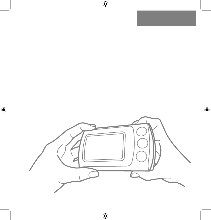
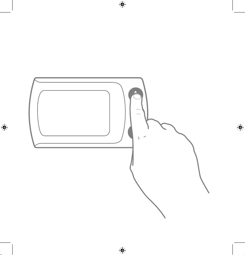
Step 5.2: Use the Up and Down
arrows to cycle through the system
options. With your system type
displayed, press the center button to
continue to Network Setup on Page 22.
LuxProducts.com | 19
HVAC SYSTEM
SETUP5.
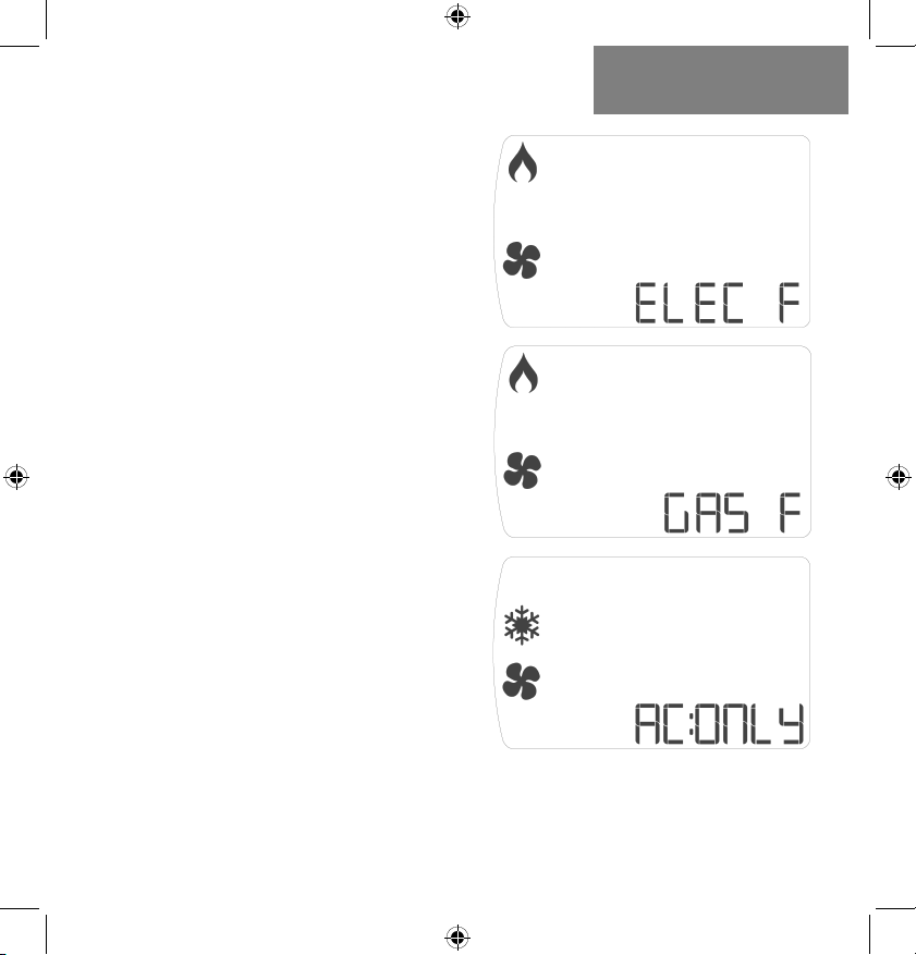
System options:
Electric Furnace:
Electric system with fan.
Thermostat calls for fan to
run with heat.
Gas Furnace:
Gas system with fan.
Thermostat calls for fan to
run with heat.
Air Conditioning Only:
Cooling Only. Thermostat
calls for fan to run with cool.
Continued on Page 20.
20 | 856.234.8803
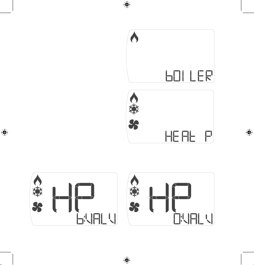
System options (con’t):
Boiler:
Boiler heating system with no
fan connected.
Heat Pump:
Heat pump system,
thermostat calls for fan to run
with heat or cool.
NOTE: If you have a heat pump system, press the center button to select.
CS1 will now ask you to confirm your valve type. Use the up and down arrows
to toggle between O & B Valves, press the center button to select:
LuxProducts.com | 21
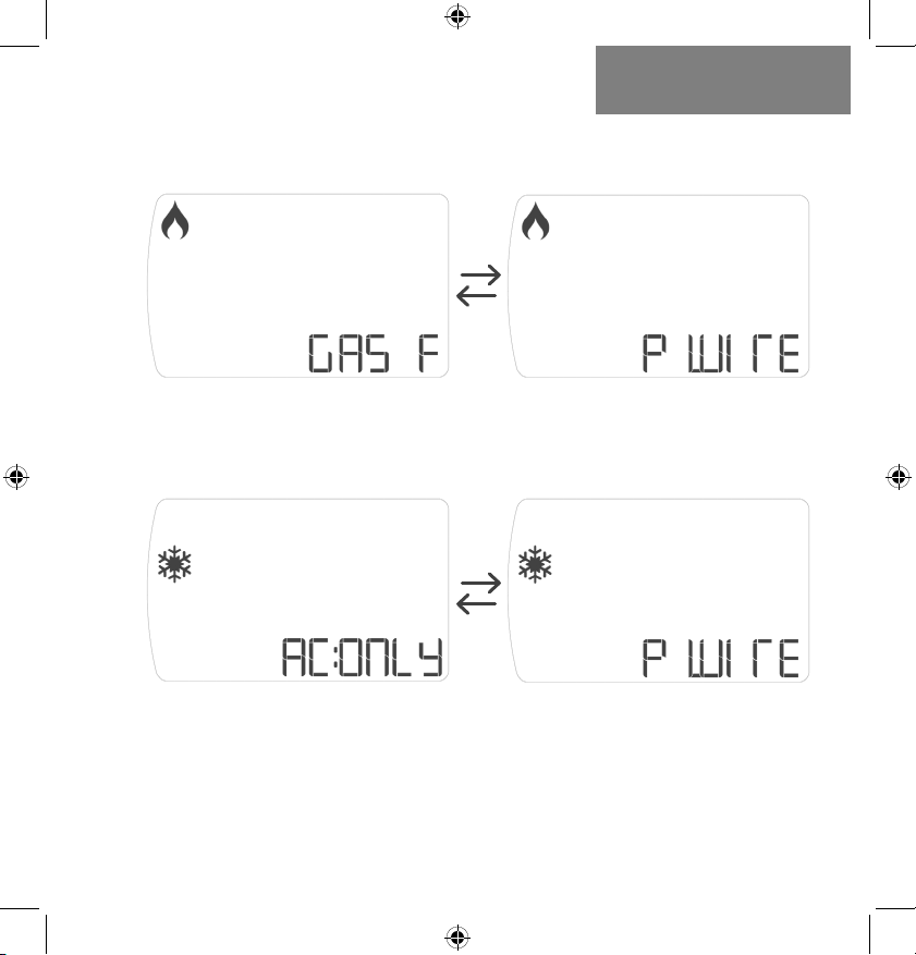
Heat With P-Wire:
This represents a furnace heat system utalizing the P-Wire.
CS1 will toggle between the screens below:
HVAC SYSTEM
SETUP5.
Cool With P-Wire:
This represents an air conditioning system utalizing the
P-Wire. CS1 will toggle between the screens below:
NOTE: When using the Power Wire, your system will only call for fan when
the device calls for heat or cool, respectively. You will not be able to run your
fan continuously or on internal air quality mode. If you would like to maintain
full fan control, please consider purchasing a LUX Power bridge at:
Shop.LUXProducts.com/PowerBridge
22 | 856.234.8803
Setup - Connecting to the Network
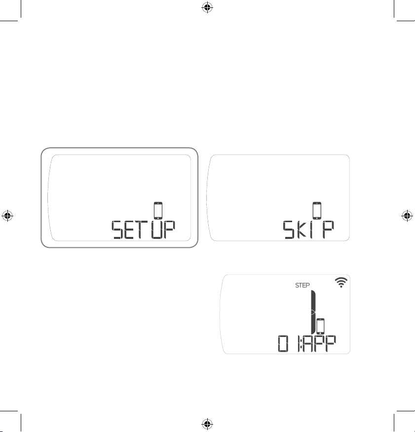
Step 6.1: After you confirm your system type, you will be
given the option to Setup or Skip WiFi Configuration. Use the
up and down buttons to change options and press center
button to confirm your selection.
Select “Setup” to connect to a network.
Step 6.2: After selecting
“Setup”, CS1 will display: “Step 1:
App”. Make sure that you have
downloaded the LUX Smart
thermostat to your smartphone.
Step 6.3: With “Step 1: App”
displayed on screen, push the
center button to continue.
LuxProducts.com | 23
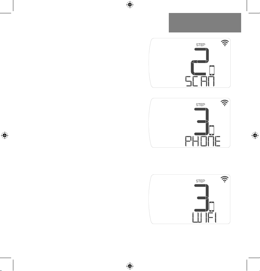
Step 6.4: When your device
displays “Step 2: Scan”, CS1
will scan for surrounding WiFi
networks.
Step 6.5: When your device
displays “Step 3: Phone”, You will
need to go to the WiFi settings in
your smartphone and select the
CS1 WiFi network (e.g. LUX-CS1-
xx-xx). The network name and
password are on the back of the
device and on a label on the box.
NOTE: If you have already recycled the
box, please return to Step 2.8 to take a
photo of the WiFi information that is on a
label on the base of your thermostat.
CONNECTING TO THE
NETWORK6.
Step 6.6: After you have
connected to the CS1 WiFi
Network, switch back to the
LUX app. Select your home
WiFi network from the list of
available networks and enter the
password. Your device will display
“Step 3:WiFi” when it is ready
to connect to your home WiFi
network.
24 | 856.234.8803
NOTE: CS1 cannot be used with a 5GHz WiFi network. Please
ensure that your wireless network is set to 2.4GHz and that
the security settings are set to open or WPA2. For more
information about how to check your network settings, please
check your router’s documentation or label.
NOTE: Open the LUX App. If you are adding your first device,
select the CS1 shaped icon. If you are adding an additional
device, start from the “Locations” menu and select the “+”
icon in the top left corner within your current location. For iOS
users, we recommend using an Apple® device with iOS8.0 or
later.
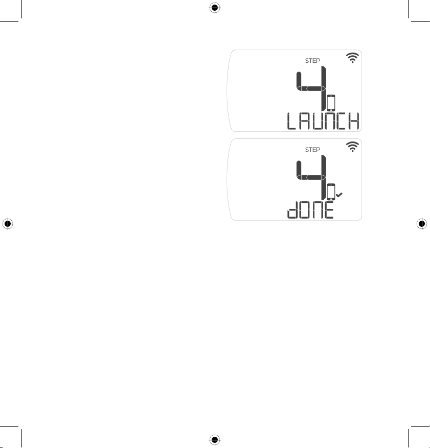
Step 6.7: Your device will
automatically display: “Step 4:
Launch” when it is attempting to
connect to the internet.
Step 6.8: After your device
has successfully connected to
the internet, you will see “Step
4: Done”, your device will then
switch to the standard operations
screen.
LuxProducts.com | 25
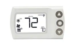
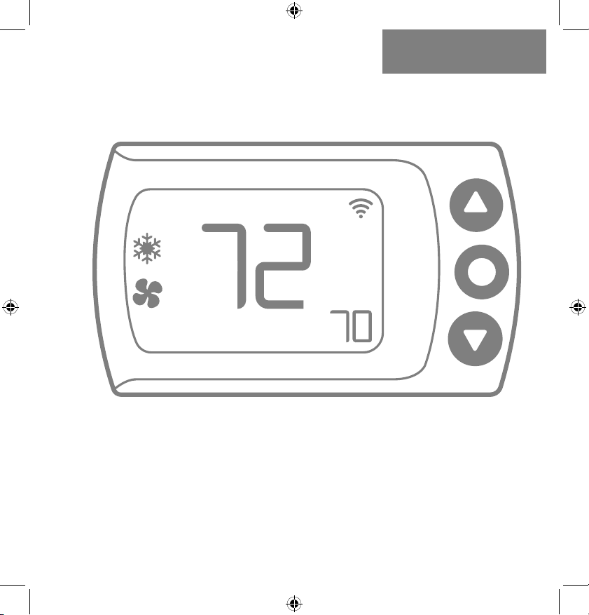
Congratulations!
When you see the thermostat’s home screen with a WiFi
icon, it means you are connected. Installation is complete
and your CS1 is ready to go. Now let’s save some energy and
make your home more comfortable. You can now control your
comfort from anywhere with an internet connection!
CONNECTING TO THE
NETWORK6.
If you need to cancel the joining process at any time,
simply press and hold the center button for 5 seconds.
ON
ROOM
HOME
SET
26 | 856.234.8803
Conventional System With C-Wire Wiring Diagram
NOTES:
• The W2 terminal is used for 2 stage heating systems only
• If you have both an RH and RC wire, please remove the red
cap from the back of the thermostat
C
C
W1
W1
W2
O/B
1 4 2
Y1
Y1
RC
RC
RH
RH
G
G
3
FAN
HEAT
(Stage 1)
HEAT (Stage 2)
COOL
TRANSFORMER
FURNACE THERMOSTAT
LuxProducts.com | 27
Heat Pump System With C-Wire Wiring Diagram
APPENDIX7.
NOTES:
• The W1 terminal is used for Auxiliary/Emergency heat or on
Dual Fuel systems
C
C
W1
W1
W2
O/B
1 4 2
Y1
Y1
RC
RC
RH
RH
G
G
3
FAN
AUX/EMER HEAT
CHANGEOVER VALVE
COMPRESSOR
TRANSFORMER
HEAT PUMP THERMOSTAT
28 | 856.234.8803
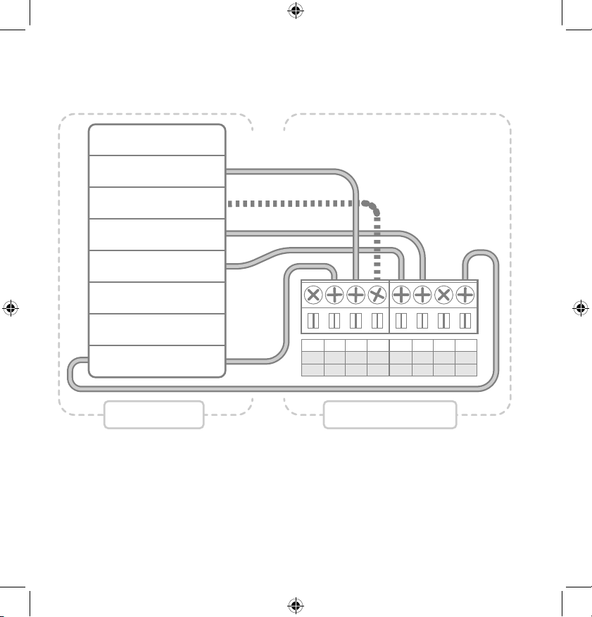
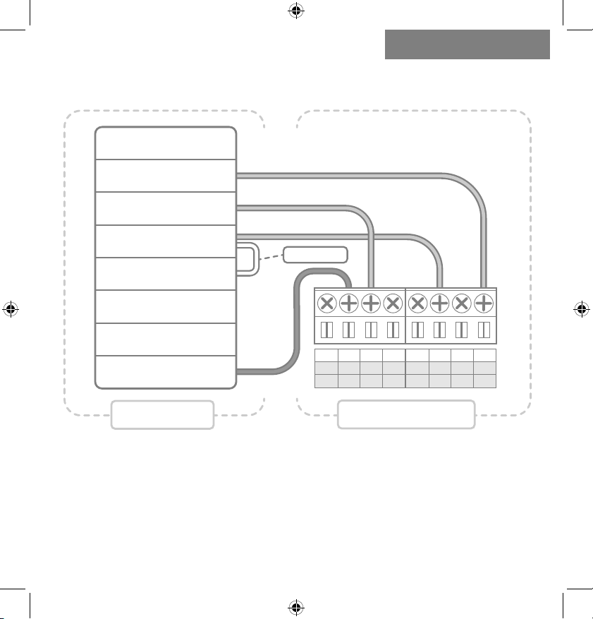
Conventional System Without C-Wire
(BEFORE Power Wire) Wiring Diagram
C
C
W1
W1
W2
O/B
1 4 2
Y1
Y1
RC
RC
RH
RH
G
G
3
FAN
POWER
HEAT
COOL
TRANSFORMER
FURNACE
THERMOSTAT
NOTES:
• At your thermostat, you will move the G Wire (dark) to the C
Terminal.
LuxProducts.com | 29
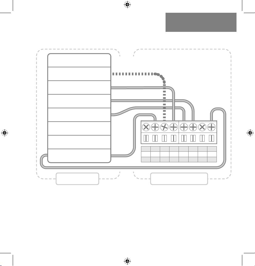
APPENDIX7.
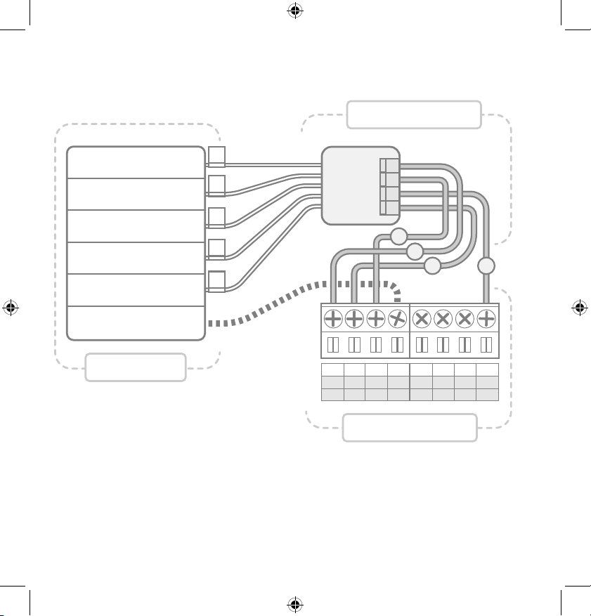
NOTES:
• The G Wire (dark) that previously went to the Fan Terminal
now connects to the Furnace Transformer
• The Power Wire (white) connects to both the Fan Terminal
as well as the Cool Terminal (with the Y Wire)
Conventional System Without C-Wire
(AFTER Power Wire) Wiring Diagram
C
C
W1
W1
W2
O/B
1 4 2
Y1
Y1
RC
RC
RH
RH
G
G
3
FAN
POWER
HEAT
COOL
TRANSFORMER
FURNACE
THERMOSTAT
P-WIRE
30 | 856.234.8803
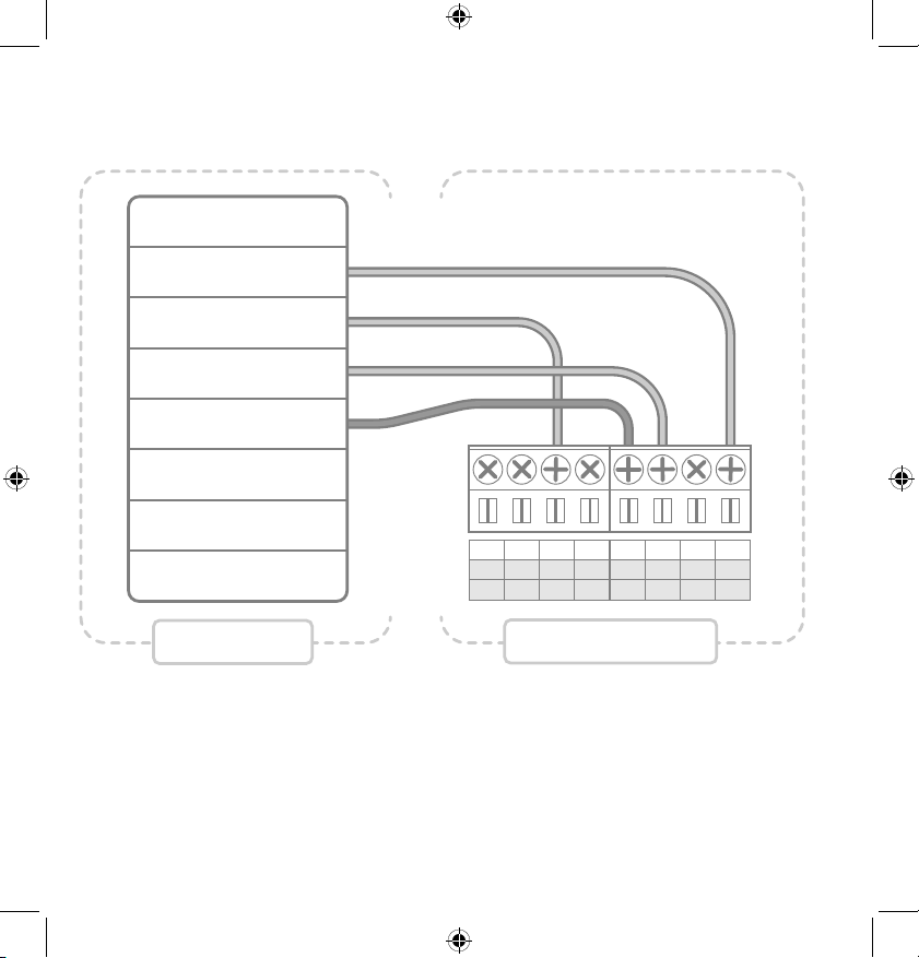
LUX Power Bridge Wiring Diagram
NOTES:
• If you have a heat pump or dual transformer system, please
call LUX Tech support.
• If you have any wires on your furnace not shown here,
please leave them as is.
FURNACE
THERMOSTAT
POWER BRIDGE
C
C
W1
W1
W2
O/B
1 4 2
Y1
Y1
RC
RC
RH
RH
G
G
3
FAN
HEAT
(Stage 1)
TRANSFORMER
COOL
COMMON
HEAT
(Stage 2)
G
Y
W
R
1
2
3
4
W
G
Y
R
C
LuxProducts.com | 31
Industry Canada Regulatory Information
This device contains licence-exempt transmitter(s)/receiver(s) that comply with Innovation, Science
and Economic Development Canada’s licence-exempt RSS(s). Operation is subject to the following two
conditions: (1) this device may not cause interference, and (2) this device must accept any interference,
including interference that may cause undesired operation of the device.
Le présent appareil est conforme aux CNR d’Industrie Canada applicables aux appareils radio exempts
de licence. L’exploitation est autorisée aux deux conditions suivantes: (1) l’appareil ne doit pas produire
de brouillage, et (2) l’utilisateur de l’appareil doit accepter tout brouillage radioélectrique subi, même si
le brouillage est susceptible d’en compromettre le fonctionnement.
License Agreement (Including ARM Limited and ST Microelectronics)
THIS SOFTWARE IS PROVIDED BY THE COPYRIGHT HOLDERS AND CONTRIBUTORS “AS IS”
AND ANY EXPRESS OR IMPLIED WARRANTIES, INCLUDING, BUT NOT LIMITED TO, THE IMPLIED
WARRANTIES OF MERCHANTABILITY AND FITNESS FOR A PARTICULAR PURPOSE ARE
DISCLAIMED. IN NO EVENT SHALL THE COPYRIGHT HOLDER OR CONTRIBUTORS BE LIABLE FOR
ANY DIRECT, INDIRECT, INCIDENTAL, SPECIAL, EXEMPLARY, OR CONSEQUENTIAL DAMAGES
(INCLUDING, BUT NOT LIMITED TO, PROCUREMENT OF SUBSTITUTE GOODS OR SERVICES;
LOSS OF USE, DATA, OR PROFITS; OR BUSINESS INTERRUPTION) HOWEVER CAUSED AND ON
ANY THEORY OF LIABILITY, WHETHER IN CONTRACT, STRICT LIABILITY, OR TORT (INCLUDING
NEGLIGENCE OR OTHERWISE) ARISING IN ANY WAY OUT OF THE USE OF THIS SOFTWARE, EVEN
IF ADVISED OF THE POSSIBILITY OF SUCH DAMAGE.
APPENDIX7.
FCC Part 15C
Warning: Changes or modifications to this unit not expressly approved by the party responsible for
compliance could void the user’s authority to operate the equipment.NOTE: This equipment has been
tested and found to comply with the limits for a Class B digital device, pursuant to Part 15 of the FCC
Rules. These limits are designed to provide reasonable protection against harmful interference in a
residential installation. This equipment generates, uses and can radiate radio frequency energy and,
if not installed and used in accordance with the instructions, may cause harmful interference to radio
communications.
However, there is no guarantee that interference will not occur in a particular installation.If this
equipment does cause harmful interference to radio or television reception, which can be determined
by turning the equipment off and on, the user is encouraged to try to correct the interference by one or
more of the following measures:
• Reorient or relocate the receiving antenna.
• Increase the separation between the equipment and receiver.
• Connect the equipment into an outlet on a circuit different from that to which the receiver is
connected.
• Consult the dealer or an experienced radio/TV technician for help.
This device complies with Part 15 of the FCC Rules. Operation is subject to the following two conditions:
(1) This device may not cause harmful interference, and (2) this device must accept any interference
received, including interference that may cause undesired operation. FCC RF Radiation Exposure
Statement
Caution: To maintain compliance with the FCC’s RF exposure guidelines, place the unit at least 20cm
from nearby persons.
Johnson Controls, Inc.
Philadelphia, PA 19112 USA
LuxProducts.com
Designed in Philadelphia.
54072
