T29UTW-7
T29UTW-7
OPERATING
INSTRUCTION
OPERATING
INSTRUCTION
T29UTW-7
T29UTW-7
OPERATING
INSTRUCTION
OPERATING
INSTRUCTION
Contents
01
Specifications
01
Thermostat’s Appearance
02
Thermostat Installation
06
First Time Setting
07
08
System Setting
Programming Settings
10
Fan Speed Setting
16
Cooling and Heating Modes
17
Child Lock
18
Configuration Menu
20
Errod Warning
19
Install your thermostat with a C wire
30
Install your thermostat without a C wire
38
Specifications
Power source :
18-30VAC 50/60Hz
IP Rating : IP21
Temperature setting range : 41°F~95°F
1°FTemperature setting accuracy:
32°F~122°FTemperature display range :
Temperature accuracy : 0.1°F
Operation temperature range : 32°F~122°F
Shipping & storage temperature : 14°F~140°F
Output : anF Relay Load Imax 24V/(0.5A)
Compressor/Valve Relay Load Imax 24V/(0.5A)
T29UTW-7
thermostat
Accessory
53
A1
02 03
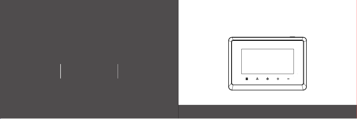
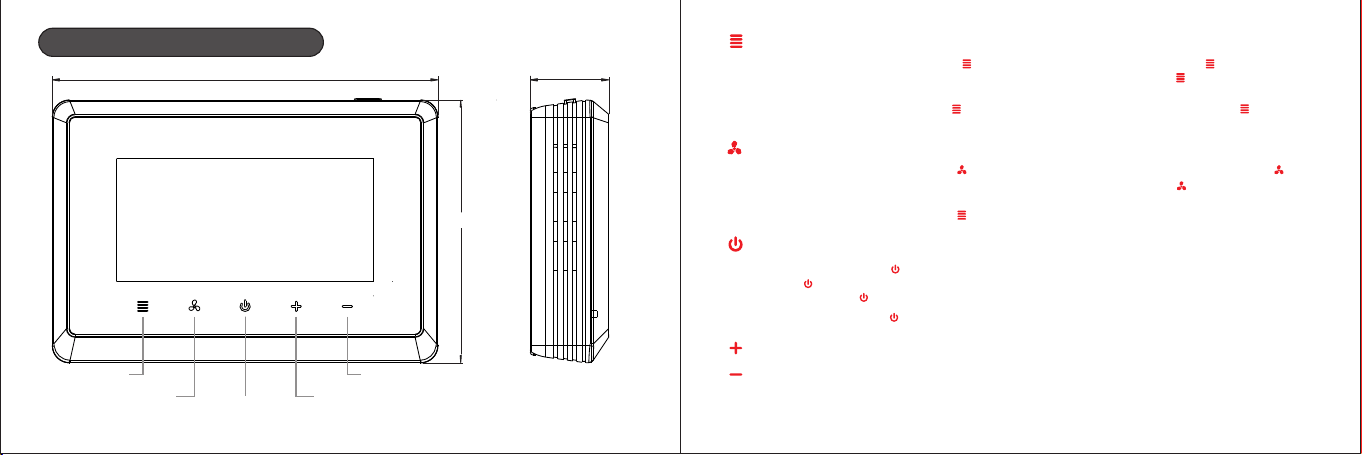
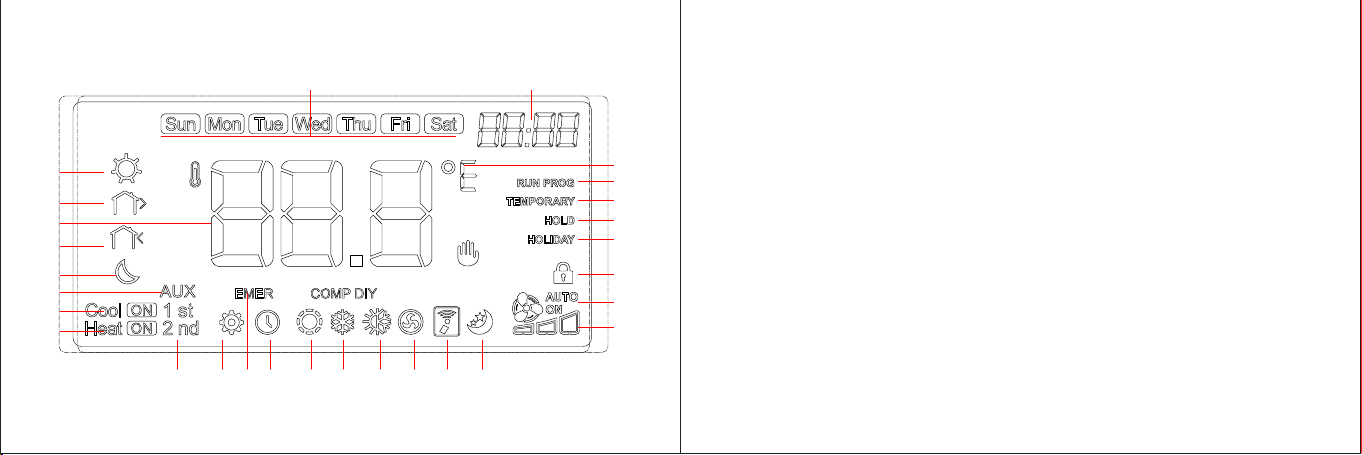
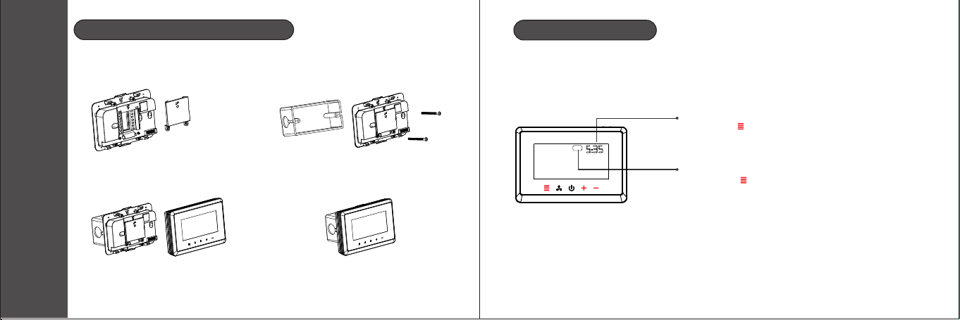
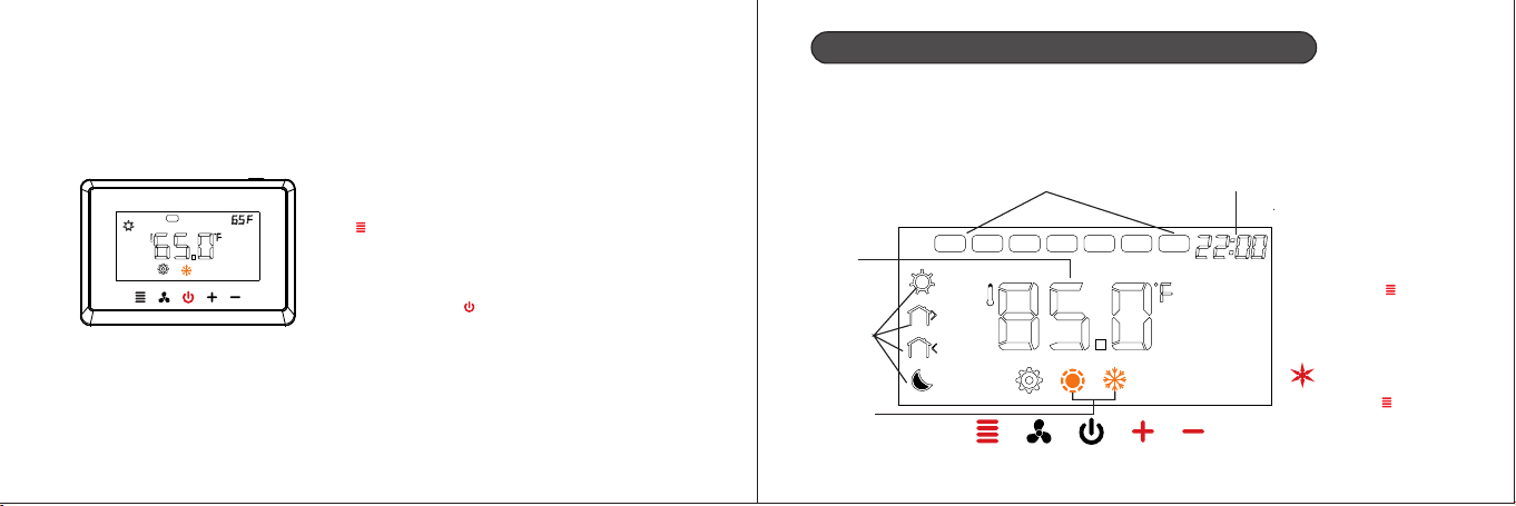
Thermostat’s appearance
135mm
92mm
27,5mm
Menu button
Fan speed button
Power
Down button
Up button
Mode button
1. Under power on status, short press button to switch the mode, long press button to enter
the programming settings. Under programming setting status, short press button to enter the
next item.
2. Under power off status, long press button to enter the menu setting. Short press button
under menu setting state to enter the next item.
Fan speed button
1.Under power-on status, short press button to switch the wind speed mode. Long press
button to enter time query. Under time query or setting status, short press button to enter
the next time setting.
2.Under power off status, short press button in menu setting state to enter the previous item.
Power button
1.In power on, short press to save and exist the time/program setting;
short press to enter into work state.
Power off, long press to remove WIFI and enter into network pair state.
2.In power off, short press to power on.
Increase button
Decrease button
* In power on, press increase button and decease button simultaneously to activate key lock.
* Without holiday mode and hold mode
A1
02 03
Thermostat’s appearance
135mm
92mm
27,5mm
Menu button
Fan speed button
Power
Down button
Up button
Mode button
1. Under power on status, short press button to switch the mode, long press button to enter
the programming settings. Under programming setting status, short press button to enter the
next item.
2. Under power off status, long press button to enter the menu setting. Short press button
under menu setting state to enter the next item.
Fan speed button
1.Under power-on status, short press button to switch the wind speed mode. Long press
button to enter time query. Under time query or setting status, short press button to enter
the next time setting.
2.Under power off status, short press button in menu setting state to enter the previous item.
Power button
1.In power on, short press to save and exist the time/program setting;
short press to enter into work state.
Power off, long press to remove WIFI and enter into network pair state.
2.In power off, short press to power on.
Increase button
Decrease button
* In power on, press increase button and decease button simultaneously to activate key lock.
* Without holiday mode and hold mode
A1
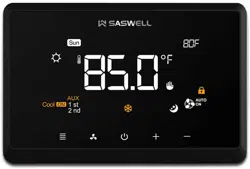
1:Week
2:Temperature setting, Time setting, Parameter setting
3:Temperature unit
4:Program run
5:Temporary mode
6:Permanent mode
7:Holiday mode
8:Key lock
9:Indicate Fan AU TO/ON
10:Indicate Filter alarm
11:Indicates leave home mode
12:Indicate U V light alarm
13:Indicate fresh air output
14:Indicate Auto mode
15:Indicate cooling mode
16:Indicate heating mode
17:Indicate clock
18:Indicate Emergency and Auxiliary Heat mode
19:Setting
1 2
4
5
6
7
8
10
9
111213141516171920
28
27
25
24
22
21
23
26
3
18
20:1 stage or 2 stage output
21:Heating Output
22:Cooling Output
23:Assistant Heating Output
24:Sleep
25:Return
26:Temperature Sampling
27:Leave
28:Wake
04 05
A1
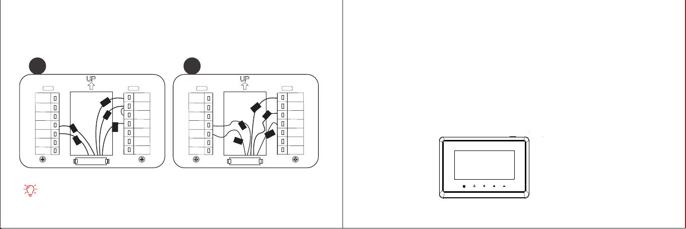
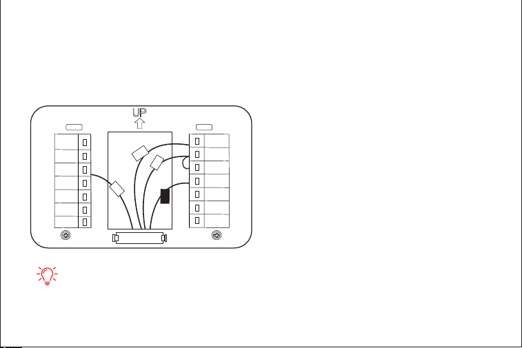
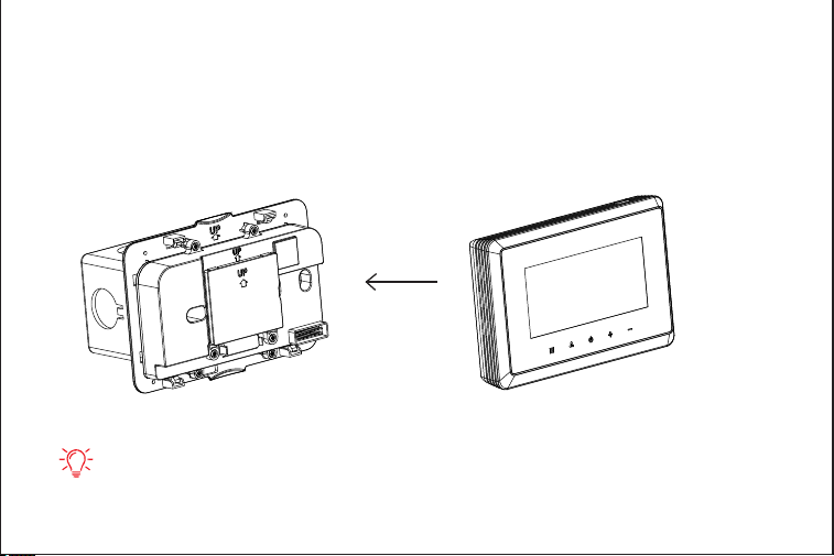
Thermostat Installation
Installation and programming
06 07
1.Unscrew terminal protective
jacket then wiring.
2.After wiredlid the terminal ,
protective jacketinstall the ,
screw.
3.Install and fasten foundation,
embed in display module.
4.Installation finished.
First Time Setting
Sat
Week setting: press “ ”or “” to adjust the week + -
short press“ ” and switch to the system setting.
Time setting: press “ ”or “” to adjust the time ,+ -
short press“ ” and switch to the week setting.
Set the current actual time and week.
A1
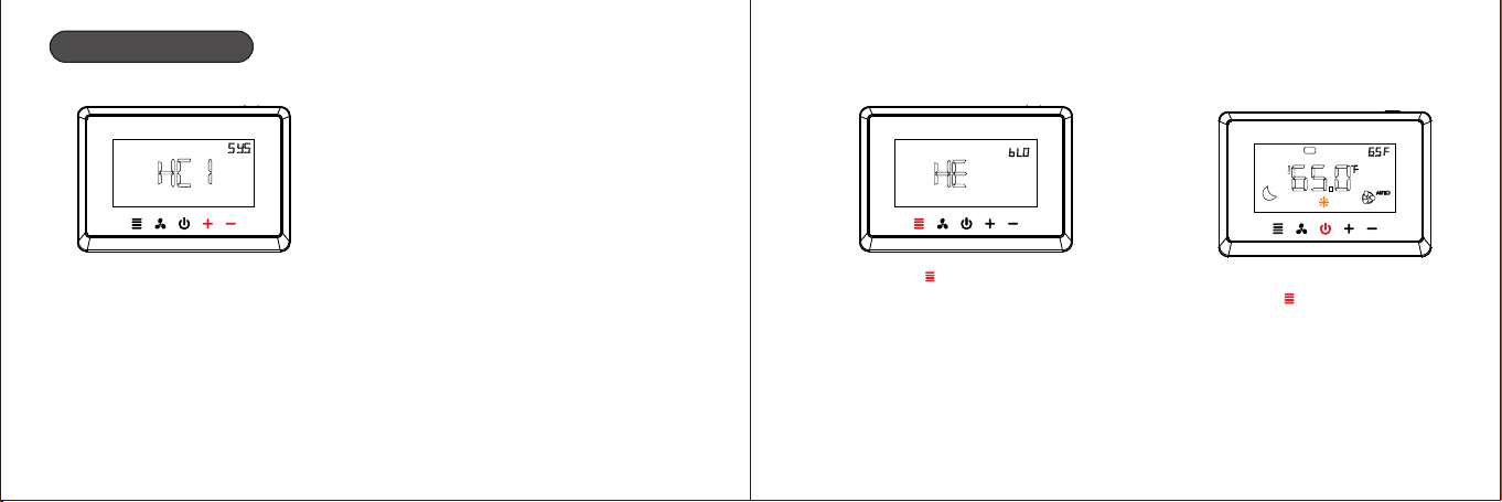
System Setting
08 09
(Multistage system )
1.press “ ”or “” to + -
select the primary
system .
2.press“ ”to confirm
the selection system
HE:Electric backup heat
HA:Fossil fuel backup heat
3.System setup completed,
press “ ”to return to the
main interface
Sat
Parameter options:(CO1,CO2,HE1,HE2,HC1,HC2,HP1,HP2,HPA)
CO1:1 cool conventional CO2:2 cool conventional
HE1:1 heat conventional HE2:2 heat conventional
HC1: 1 heat/1 cool conventional HC2: 2 heat/2 cool conventional
H 1: 1 compressor heat pump,1-AUX
HP2: 2 compressors or 2 speed compressor heat pump,1-AUX
HPA: 2 compressors or 2 speed compressor heat pump, 2-AUX
P
A1

10 11
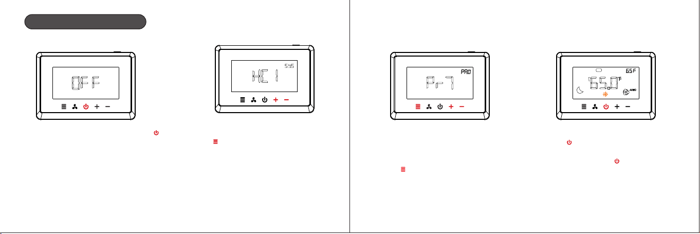
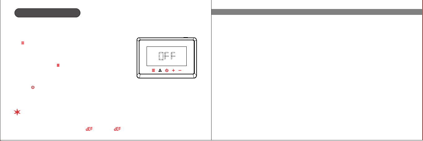
Programming Settings
1.Short press the power button “ ”,
and then the screen shows “OFF”.
2.Long press the menu button
“ ”for 5s until the system
selection interface is displayed
and select the system set up
previously .
3.After system selection, select
programming mode: press “ ”+
or “ ”for switch the programming-
mode(Pr0/Pr2/Pr7),and press
“ ”to confirm and save the options.
Pr0:Non-programmable
Pr2:Work days+Friday&Saturday
Pr7:7 days individually programming
4.Short press the power button
“ ”,and the screen shows
“OFF”,then short press the
power button“ ”again to enter
the programming main interface
Sat
A1

10 11
Programming Settings
1.Short press the power button “ ”,
and then the screen shows “OFF”.
2.Long press the menu button
“ ”for 5s until the system
selection interface is displayed
and select the system set up
previously .
3.After system selection, select
programming mode: press “ ”+
or “ ”for switch the programming-
mode(Pr0/Pr2/Pr7),and press
“ ”to confirm and save the options.
Pr0:Non-programmable
Pr2:Work days+Friday&Saturday
Pr7:7 days individually programming
4.Short press the power button
“ ”,and the screen shows
“OFF”,then short press the
power button“ ”again to enter
the programming main interface
Sat
A1
12 13
5.Long press the menu button
“ ”for 5s to enter the programming
setting.
please Keep all the buttons lights on
before performing this operation,if not,
please press “ ”
7 days programming-Time/temperature setting
Separate programming settings for each day (Pr7)
(the programming setting are different from Sunday to Monday )
The are 4 periods each day by default
Sat
Thu
Fri
WedTueMon
Sun
week setting time setting
Four
periods
for a day
temperature
setting
1.Week setting
2.Time setting
3.Temperature setting
press “ ”“” to adjust + -
the week / time /
temperature, short
short press“ ” to save
the setting and switch
to next period setting.
Heating/
cooling
mode
long press “ ” for 5s
to switch the heating
mode or cooling mode
Sat
A1
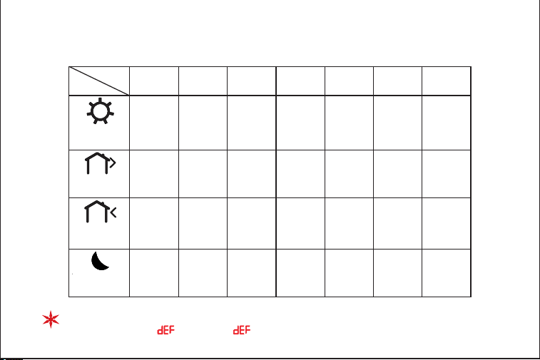
14 15
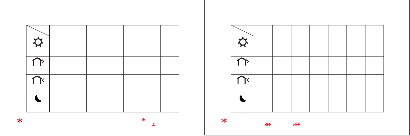
Default setting (heating) Default setting (cooling)
Exit programming settings : short press power button “ ”
Return to the previous step : short press fan speed button “ ”
Morning
6:00
Out door
8:00
Back home
18:00
Night
22:00
periods
week
Sun
Mon Tue Wed Thu
Fri Sat
72°F
61°F
72°F
61°F
72°F
61°F
72°F
61°F
72°F
61°F
72°F
61°F
72°F
61°F
Morning
6:00
Out door
8:00
Back home
18:00
Night
22:00
periods
week
Sun
Mon Tue Wed
Thu
Fri Sat
77°F 77°F 77°F 77°F 77°F 77°F 77°F
Restore default setting: long press “ ”and “ ”for more than 5s until the+ -
screen shows “ ”and the “ ”flash 3times.
72°F 72°F 72°F 72°F 72°F 72°F 72°F
61°F 61°F 61°F 61°F 61°F 61°F 61°F
77°F 77°F 77°F 77°F 77°F 77°F 77°F
82°F 82°F 82°F 82°F 82°F 82°F 82°F
82°F 82°F 82°F 82°F 82°F 82°F 82°F
A1
14 15
Default setting (heating) Default setting (cooling)
Exit programming settings : short press power button “ ”
Return to the previous step : short press fan speed button “ ”
Morning
6:00
Out door
8:00
Back home
18:00
Night
22:00
periods
week
Sun
Mon Tue Wed Thu
Fri Sat
72°F
61°F
72°F
61°F
72°F
61°F
72°F
61°F
72°F
61°F
72°F
61°F
72°F
61°F
Morning
6:00
Out door
8:00
Back home
18:00
Night
22:00
periods
week
Sun
Mon Tue Wed
Thu
Fri Sat
77°F 77°F 77°F 77°F 77°F 77°F 77°F
Restore default setting: long press “ ”and “ ”for more than 5s until the+ -
screen shows “ ”and the “ ”flash 3times.
72°F 72°F 72°F 72°F 72°F 72°F 72°F
61°F 61°F 61°F 61°F 61°F 61°F 61°F
77°F 77°F 77°F 77°F 77°F 77°F 77°F
82°F 82°F 82°F 82°F 82°F 82°F 82°F
82°F 82°F 82°F 82°F 82°F 82°F 82°F
A1
17
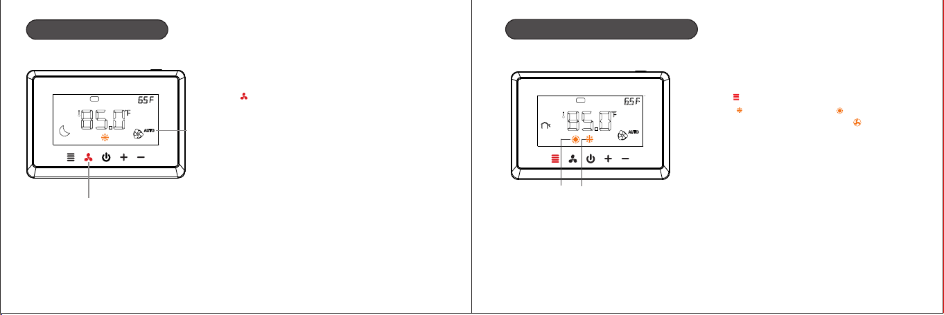
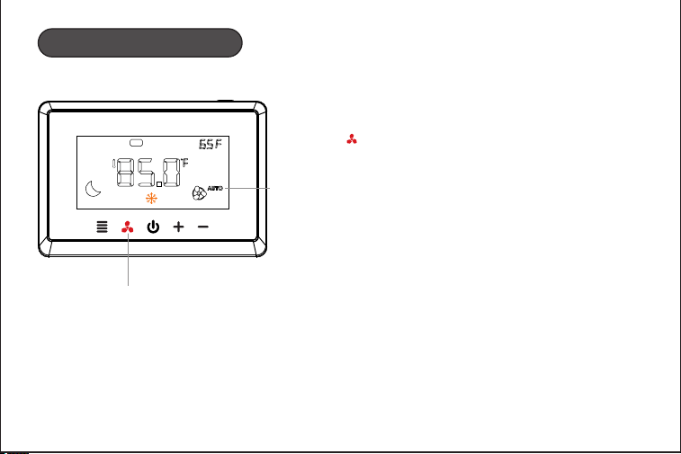
Fan speed setting
Sat
Fan speed
button
Fan speed mode setting : short press
“ ” for switching “AUTO” or “ON”mode.
mode
AUTO:Automatic mode
ON:FAN ON mode
16
Sat
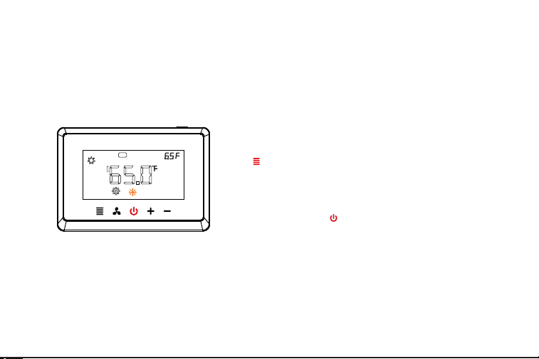
Cooling and Heating Modes
Short press the menu button
“ ”for switching cooling mode
“ ”or heating mode “ ” or
single speed fan mode “ ”
Heating
mode
Cooling
mode
A1
17
Fan speed setting
Sat
Fan speed
button
Fan speed mode setting : short press
“ ” for switching “AUTO” or “ON”mode.
mode
AUTO:Automatic mode
ON:FAN ON mode
16
Sat
Cooling and Heating Modes
Short press the menu button
“ ”for switching cooling mode
“ ”or heating mode “ ” or
single speed fan mode “ ”
Heating
mode
Cooling
mode
A1
18 19
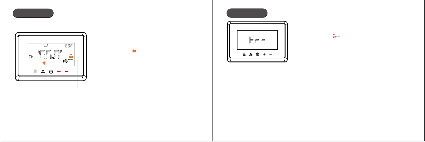
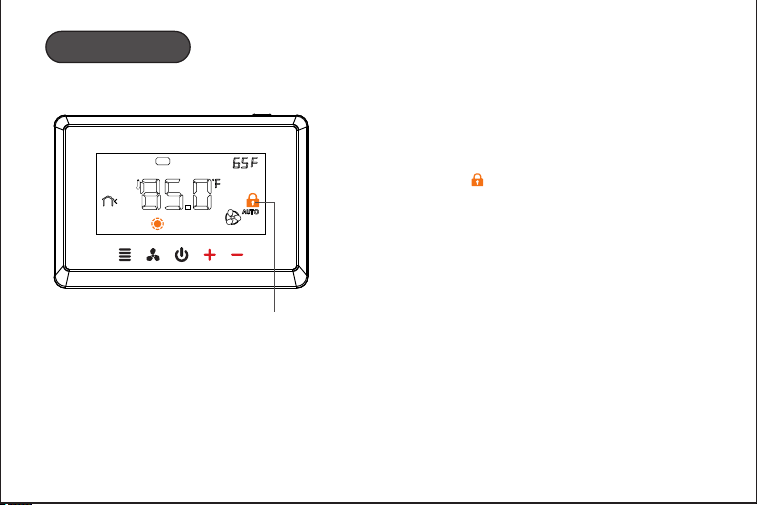
Child Lock
Sat
Child lock
Press the “ ” and “ ” buttons for 5s+ -
at the same time to open / close the
child lock “ ”.
Errod Warning
Room Temp(inside room sensor)
broken or short cut,the thermostat
will have “ ”
A1
18 19
Child Lock
Sat
Child lock
Press the “ ” and “ ” buttons for 5s+ -
at the same time to open / close the
child lock “ ”.
Errod Warning
Room Temp(inside room sensor)
broken or short cut,the thermostat
will have “ ”
A1
2120
Configuration Menu
The configuration menu setting :
1.In the state of shutdown,long press menu button
“ ”for 5s to enter the configuration parameter
programming setting.
2.Press “ ”or “ ”to select the configuration parameter +
-
setting,then press “ ”to save and switch to the next
item setting.
3.After all the parameters are set up, press power
button “ ”exit the setting and return to the OFF stage.
1.The thermostat will exit the configuration parameter setting automatically
and return to the shutdown state if there is no any operation whin 30s.
2.Restore default setting: during setup, long press “ ”and “ ”for more than+ -
5s until the screen shows “ ”and the “ ”flash 3times.
System type option(SYS)
Parameter options:(CO1,CO2,HE1,HE2,HC1,HC2,HP1,HP2,HPA)
CO1:1 cool conventional CO2:2 cool conventional
HE1:1 heat conventional HE2:2 heat conventional
HC1: 1 heat/1 cool conventional HC2: 2 heat/2 cool conventional
H 1: 1 compressor heat pump,1-AUX
HP2: 2 compressors or 2 speed compressor heat pump,1-AUX
Factory default: HC1
HPA: 2 compressors or 2 speed compressor heat pump, 2-AUX
P
A1
22 23
Intelligent recovery option (rEC)
Parameter options:(OFF,ON)
OFF: Deactivate the intelligent recovery function
ON: Activate the intelligent recovery function
Factory default:OFF
Manual/Autochangeover option(CHA)
Parameter options: (OFF,ON)
OFF: Manual changeover ON: Auto changeover
Factory default:OFF
First cooling cycle rate(CCY)
Parameter options:(1°F~6°F)
Factory default:1°F
First heating cycle rate(HCY)
Parameter options:(1°F~6°F)
Factory default:1°F
Second cooling cycle rate(C2S)
Parameter options:(1°F~6°F)
Factory default:1°F
Second heating cycle rate(H2S)
Parameter options:(1°F~6°F)
Factory default:1°F
Emergency heat cycle rate(CrY)
Parameter options:(1°F~6°F)
Factory default:1°F
A1

24 25
Compressor lockout delay option(dEL)
Parameter options:(0~5)
To protect the compressor from short cycling, you can select compressor off-time cycle
between 0~5 minutes
Factory default:3
When the thermostat compressor time delay occurs, lockout.
No heat pump heat type option(BLO)
Parameter options:(HA,HE)
HA: Fossil fuel backup heat HE: Electric backup heat
Factory default:HE
HP1, HP2 and HPA system are Auxiliary heating
Display backlight option(BLL)
Parameter options:(1,2)
1:No backlight display
2:The backlight come on for approximately 30s when any button is touched
Factory default:2
Temperature recalibration option(CAL)
Parameter options:(-8~+8°F)
Factory default:0
℉ or ℃ readout option(FC)
Parameter options:(℉ , ℃)
Factory default:℉
A1
26 27
Program option(Pr0)
Parameter options:(Pr7,Pr0)
Pr7: 7-day program function for the thermostat
Pr0: non-program function for the thermostat
Factory default: 7Pr
17.Filter replacement run time option( FIL)
Parameter options:(00-12)
This is a reminder to change or clean your air filter. This time can be set from 0 to
12 months in 1 month increments.
Factory default: 00
1.The thermostat will display the “ ” after a set time of operation.
2.Selection of 00 will cancel the function.
18.UV lamp replacement run time option(UUL)
Parameter options:(ON,OFF)
ON: It means starts to counting for 0 day to 400 day
OFF: It means cancel the function
Factory default:OFF
The thermostat will display the “ ” when UV time(400 days) has expired.
20.Remote sensor option(SEn)
Parameter options:(0,1,2)
0: No remote sensor
1: Outdoor control sensor (See Menu item 21 Heat pump temperature lockout)
2: Indoor sensor. if the thermostat is installed with an indoor remote sensor, display
will show the read temperature from the indoor sensor.
If the option is 1,2,please choose NTC-10 sensor.
Factory default:0
A1

28 29
Heat pump compressor lockout option(HPL)
Parameter options:(0 ,15 , 20 ,25 , ,35 , )°F °F °F °F 30°F °F 40°F
0:No heat pump compressor lockout
15 , 20 , 25 , 30 , 35℉,40℉:heat pump compressor lockout temperature°F °F °F °F
Factory default:0
This option apply only to HP1, HP2, HP setting in system type option and only works when A
remote sensor option (menu item 20) is set 2.
Heat pump auxiliary heating temperature lockout option(AUL)
Parameter options:(0℉,40℉,45℉,50℉, 55℉,60℉)
0:No auxiliary heating temperature lockout
40℉,45℉,50℉,55℉,60℉:heat pump auxiliary heating temperature lockout
Factory default:0
This option apply only to HP1, Hp2, HP setting in system type option and only works when A
remote sensor option (menu item 20) is set 2.
Auto changeover dead band option(dbA)
Parameter options:(4~8℉)
Factory default:4℉
O/B port selection direction(Ob)
O: O/b terminal is output in cooling mode
b: O/b terminal is output in heating mode
Factory default: b
ventilator(FAN)
0~60 min
Factory default: 0
A1
CHECKPOINT:C WIRE
√
Do your have a C wire connected to you old thermostat ?
YES
Great, please continue
to the NEXT PAGE.
NO
Go to install
with a ECM.
RC RH G Y W C RC RH G Y W C
TIPS:
The wiring on your old thermostat may look different, just check to see if there’s
a C wire.
Install your thermostat
with a C wire
If you have a C wire, it will power your thermostat. you won’t need the Electric
Control Module included in the box.
TIPS:
TO install accessories(humidifier, dehumidifier or ventilator)please refer to the wiring
diagrams at wiring.
3130
A1
32 33
STEP2
Unscrew the mounting plate of your old thermostat to remove it from the wall.
STEP1
Carefully disconnect and label the wires from your old thermostat one at a time,
using the labels provided.
RC RH G Y W C
TIPS:
If you have a jumper between RC,RH,OR R, leave it alone.
Only label the wires that run from your wall into a terminal block.
RC
C
G
Y
1
W
1
W
1
RC RH G Y W C
R
C
C
G
Y
1
W
1
W
/
W
1
!
WARNING:
Be careful, as some thermostat may contain mercury.
Recycle your old thermostat safely with your local hazardous waste facility.
A1
C
RC
RH
W1
W2
AC+
AC-
RT+
RT-
S
G
Y1
Y2
O/B
C
RC
RH
W1
W2
AC+
AC-
RT+
RT-
S
G
Y1
Y2
O/B
R
C
C
G
Y
1
W
1
35
CHECKPOINT: INSERT YOUR R WIRE(S)
√
Do your have more than one R wire?
(That includes R,RC,and RH)
YES
Insert your wires:
R or RC → RC
RH → RH
NO
Insert your single wire:
R,RC,or RH→ RC
34
C
RC
RH
W1
W2
AC+
AC-
RT+
RT-
S
G
Y1
Y2
O/B
C
G
Y
1
RH
RC
R
H
G
Y
1
W
1
STEP3
Insert your remaining wires into the side (not the front) of their corresponding
terminal blocks.
TIPS:
1.Press the terminal block levers to insert the wires more easily.
2.When a wire has been connected correctly, the level on the block will lower.
STEP4
Tug on the wire gently to ensure they are securely connected.
W
1
* Note: Do not jumper RC or RH
RC
C
A1
C
RC
RH
W1
W2
AC+
AC-
RT+
RT-
S
G
Y1
Y2
O/B
C
RC
RH
W1
W2
AC+
AC-
RT+
RT-
S
G
Y1
Y2
O/B
36
STEP5
Carefully push any excess wires back into the hole and ensure there are no drafts
coming from the hole(s) in the wall.
R
C
C
G
Y
1
1
√
RC
C
G
X
TIPS:
Large holes behind your thermostat will affect temperature readings.
Prevent drafts by covering the holes.
W1
W
1
Y
1
STEP6
Turn the power to your HVAC system back on using the master switch or at the
circuit breaker box.
Congratulations, you did it!
Say hi to your new thermostat! To complete your setup and registrations,
follow the instructions on your thermostat screen.
37
A1
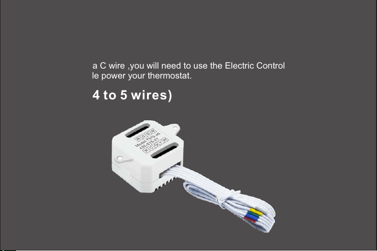
Install your thermostat
without a C wire
If you don’t have a C wire ,you will need to use the Electric Control Module
included to reliable power your thermostat.
CHECKPOINT: 3 OR 4 WIRES
√
The Electric Control Module requires your system to have either of the following:
4 wires W/W1,Y/Y1,G,and R(or RC or RH)
Do you have these wires?
YES
Great, please continue
to the NEXT PAGE.
NO
Please check compatibility
or contact us!
RC RH G Y W C RC RH G Y W C
The Electric Control Module
will work with your system!
3938
(Optional 4 to 5 wires)
A1
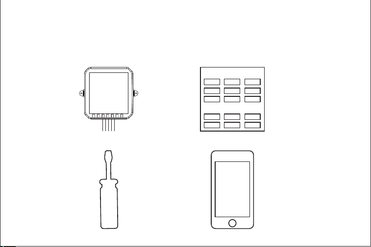
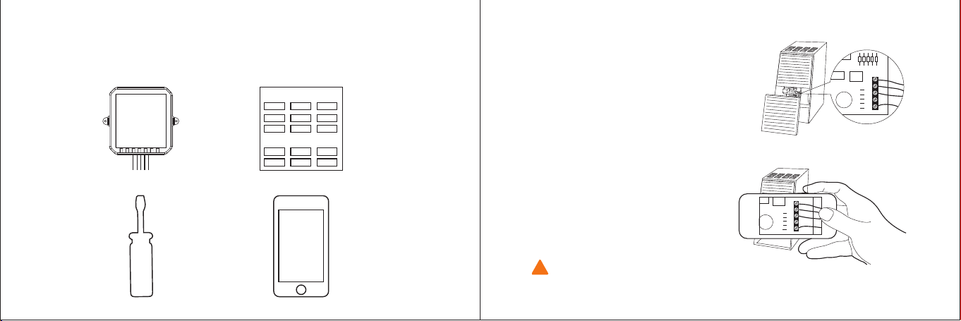
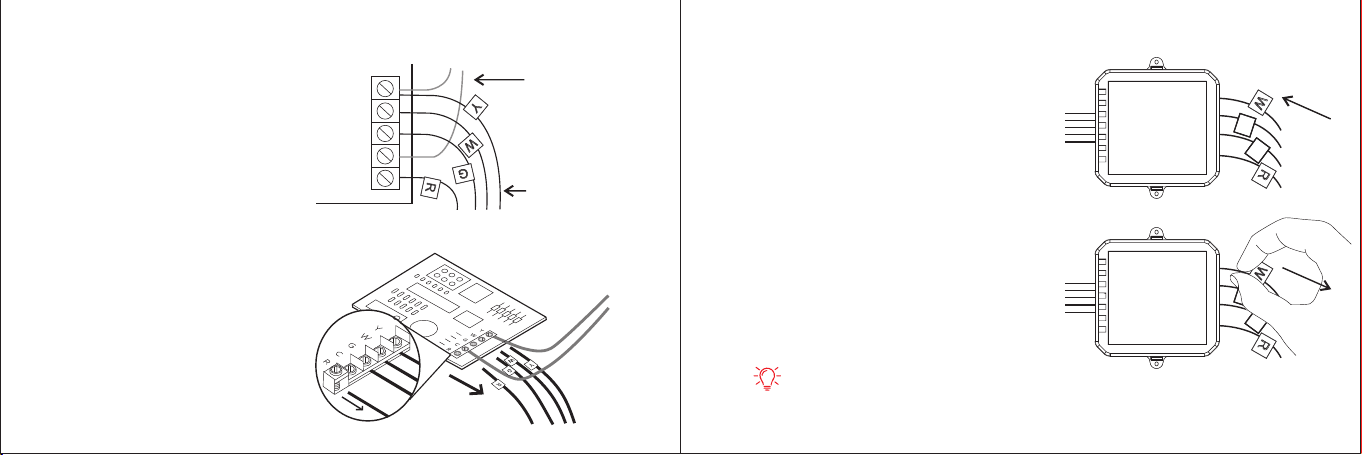
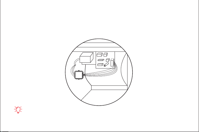
STEP1
Take your Electric Control Module ,wire labels, tools, your smart-phone, and go to
your HVAC system.
Thermostat wire labe
Label wires at your:
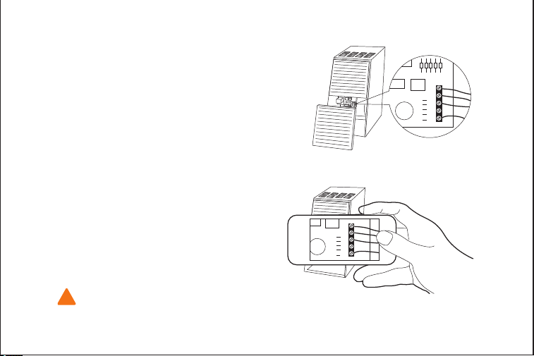
STEP2
Open your HAVC system’s cover to
reveal at control board.
STEP3
Take a picture of the wires
connected to your control board.
You may need to reference this
photo later on.
HVAC system contain high voltage wires. Use caution when working with the
control board. If you’d rather leave it up to a professional.
WARNING:
!
Cont ro l bo ar d
Y
W
G
C
R
Y
W
G
C
R
4140
A1
STEP1
Take your Electric Control Module ,wire labels, tools, your smart-phone, and go to
your HVAC system.
Thermostat wire labe
Label wires at your:
STEP2
Open your HAVC system’s cover to
reveal at control board.
STEP3
Take a picture of the wires
connected to your control board.
You may need to reference this
photo later on.
HVAC system contain high voltage wires. Use caution when working with the
control board. If you’d rather leave it up to a professional.
WARNING:
!
Cont ro l bo ar d
Y
W
G
C
R
Y
W
G
C
R
4140
A1
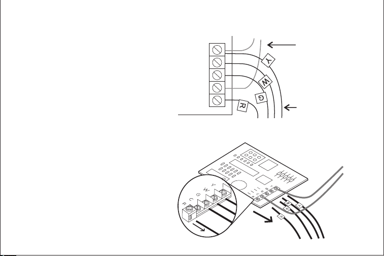
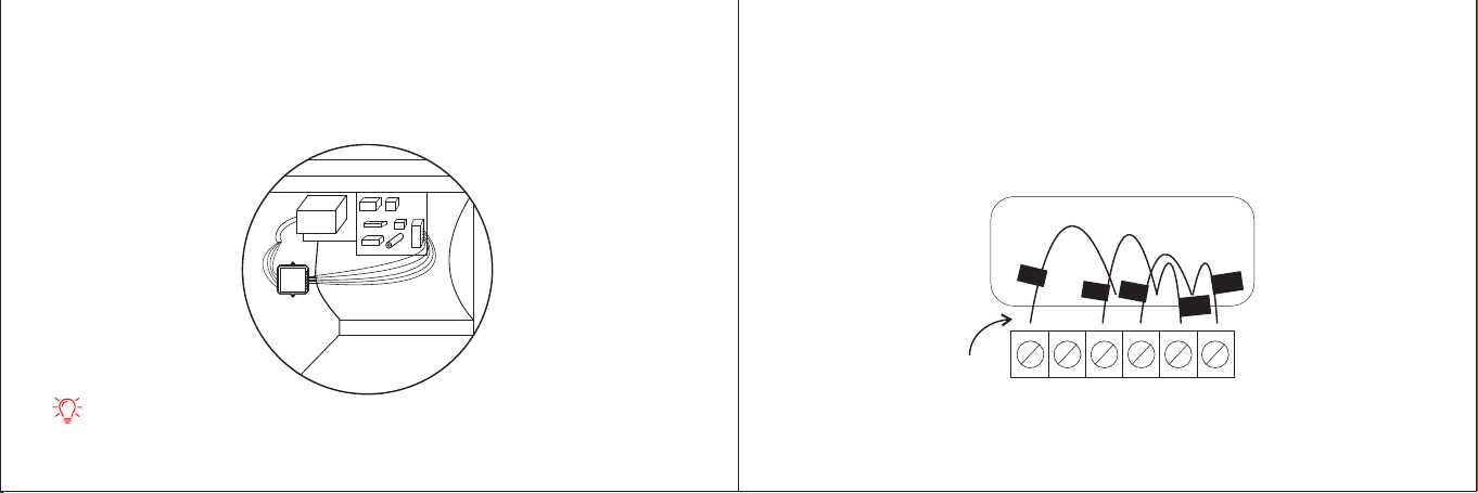
STEP4
Label only the R,Y,or Y1,G,and W or
W1 wires with the matching labels
provided.
If you have more than one wire going
into these terminals, only label those
going to your thermostat.
STEP5
Disconnect the wires labeled
R,Y,G,and W from the control
board.
Y
W
G
C
R
Y
W
R
G
Wires going
to You're a/C
(ignore this )
Wires going to
Your thermostat
control board
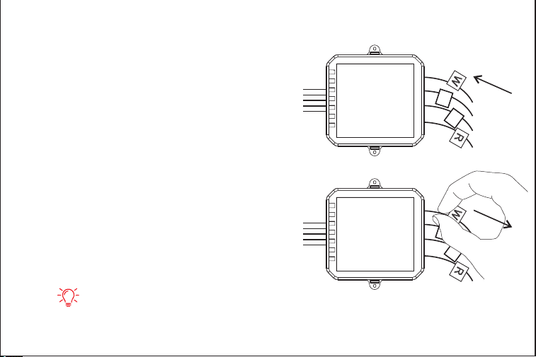
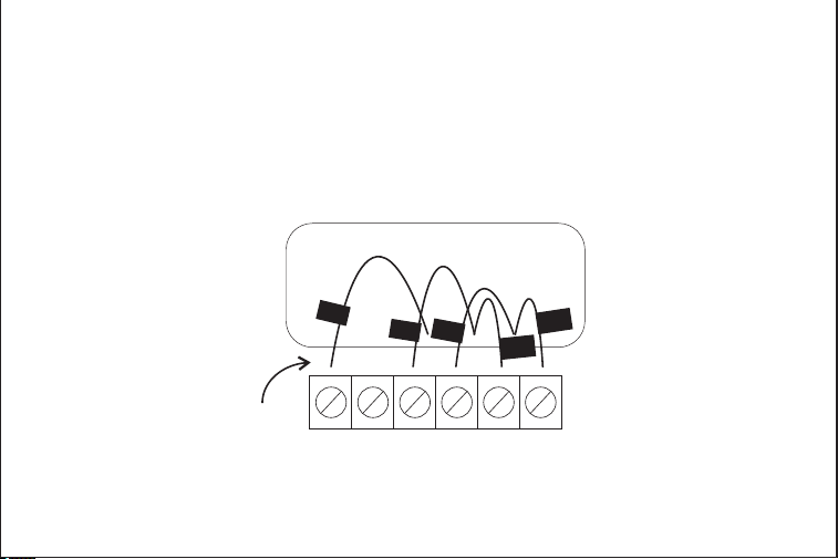
STEP6
Connect the wires you disconnected
from the control board into their
matching gray terminal blocks on
the Electric Control Module.
STEP7
Tug on the wires gently to
ensure they are securely
connected.
TIPS:
1.Press the buttons to insert the wires more easily.
2.When a wire has been connected correctly, the button on that block will lower.
S
W
R
C
S
W
C
R
C
S
S
W
R
C
S
W
C
R
C
S
4342
A1
STEP4
Label only the R,Y,or Y1,G,and W or
W1 wires with the matching labels
provided.
If you have more than one wire going
into these terminals, only label those
going to your thermostat.
STEP5
Disconnect the wires labeled
R,Y,G,and W from the control
board.
Y
W
G
C
R
Y
W
R
G
Wires going
to You're a/C
(ignore this )
Wires going to
Your thermostat
control board
STEP6
Connect the wires you disconnected
from the control board into their
matching gray terminal blocks on
the Electric Control Module.
STEP7
Tug on the wires gently to
ensure they are securely
connected.
TIPS:
1.Press the buttons to insert the wires more easily.
2.When a wire has been connected correctly, the button on that block will lower.
S
W
R
C
S
W
C
R
C
S
S
W
R
C
S
W
C
R
C
S
4342
A1
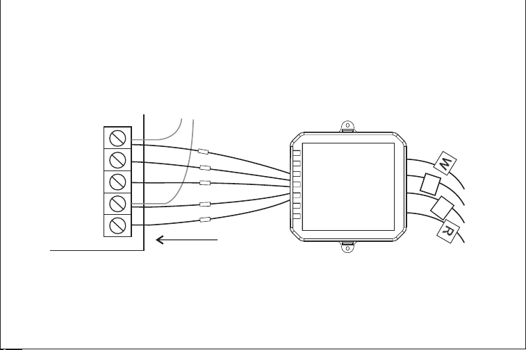
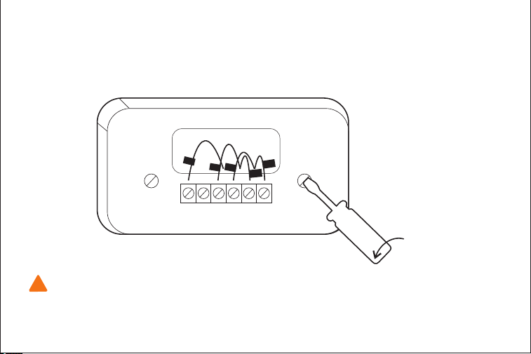
STEP8
Connect the five white wires coming out of your Electric Control Module to their
correspending terminals on the control board .
Y
W
G
C
R
control board
s
W
R
c
S
W
C
R
Electric Control Module
s
c
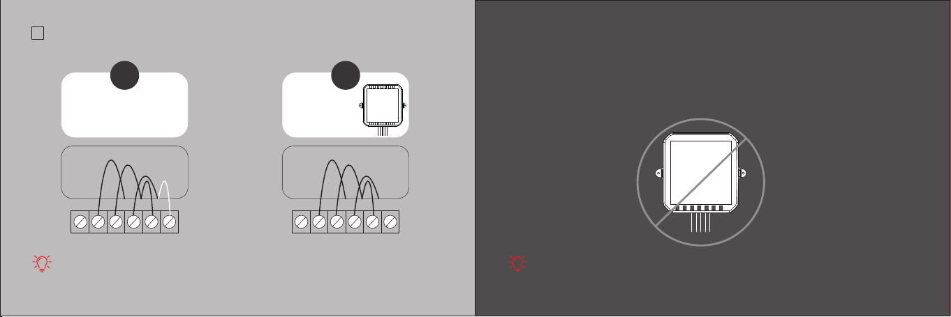
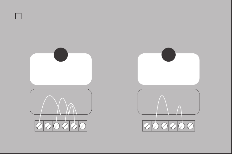
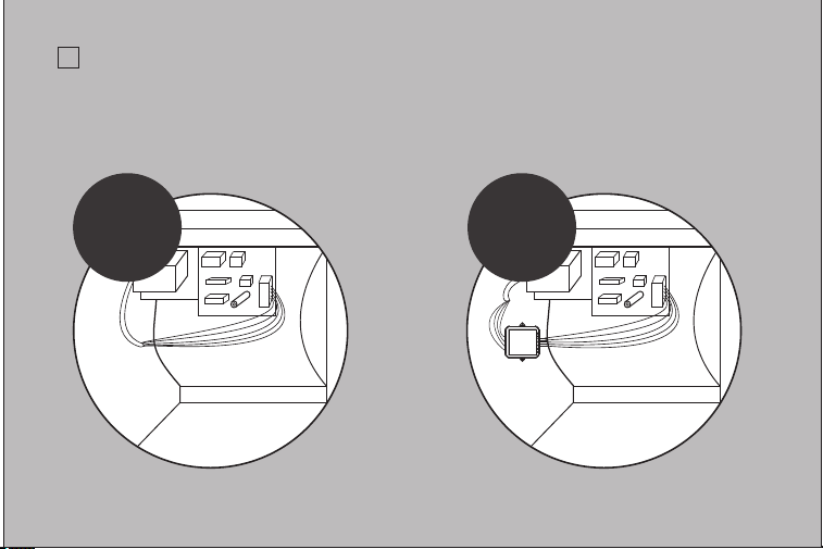
CHECKPOINT: Electric Control Module
√
Check that you have installed the Electric Control Module correctly.It should be
installed between your thermostat wiring and your control board.
BEFORE AFTER
4544
A1
STEP8
Connect the five white wires coming out of your Electric Control Module to their
correspending terminals on the control board .
Y
W
G
C
R
control board
s
W
R
c
S
W
C
R
Electric Control Module
s
c
CHECKPOINT: Electric Control Module
√
Check that you have installed the Electric Control Module correctly.It should be
installed between your thermostat wiring and your control board.
BEFORE AFTER
4544
A1
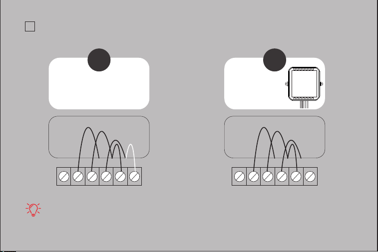
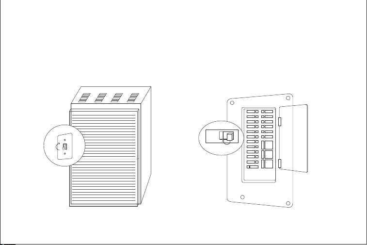
STEP9
Mount the Electric Control Module inside your HAVC system,taking care not to
strain the wires.
Close the HVAC cover panel securely return to your thermostat.
TIPS:
Make sure your HVAC panel is fully closed. Some systems will not turn on if
the cover panel has not been closed properly.
STEP10
Back at your thermostat:
Carefully disconnect and label the wires from your old thermostat one at a time,
using the labels provided.
If you have a jumper between RC,RH,or R leave it alone.
Only label the wires that run from your wall into a terminal block.
RC RH G Y W C
RC
C
G
Y
1
W
1
W
1
4746
A1
C
RC
RH
W1
W2
AC+
AC-
RT+
RT-
S
G
Y1
Y2
O/B
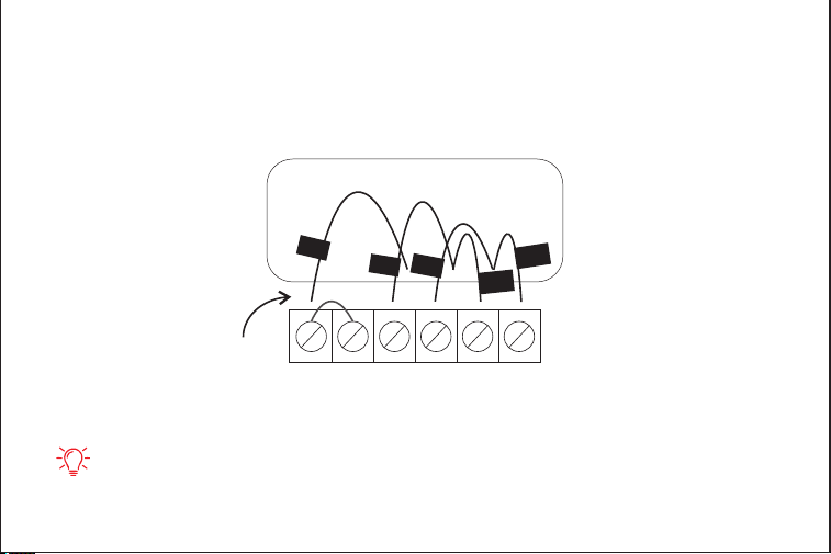
STEP11
Unscrew the mounting plate of your old thermostat to remove it from the wall.
RC RH G Y W C
R
C
C
G
Y
W
1
W
WARNING:
Be careful,as some thermostat may contain mercury.
Recycle your old thermostat safely with your local hazardous waste facility.
STEP12
Remove the RC,C and S labels from the label sheet and attach them to the
wires as shown below:
R/RC/RH→RC
G→C
Y→S
RC
C
W
1
S
4948
W
/
!
A1
C
RC
RH
W1
W2
AC+
AC-
RT+
RT-
S
G
Y1
Y2
O/B
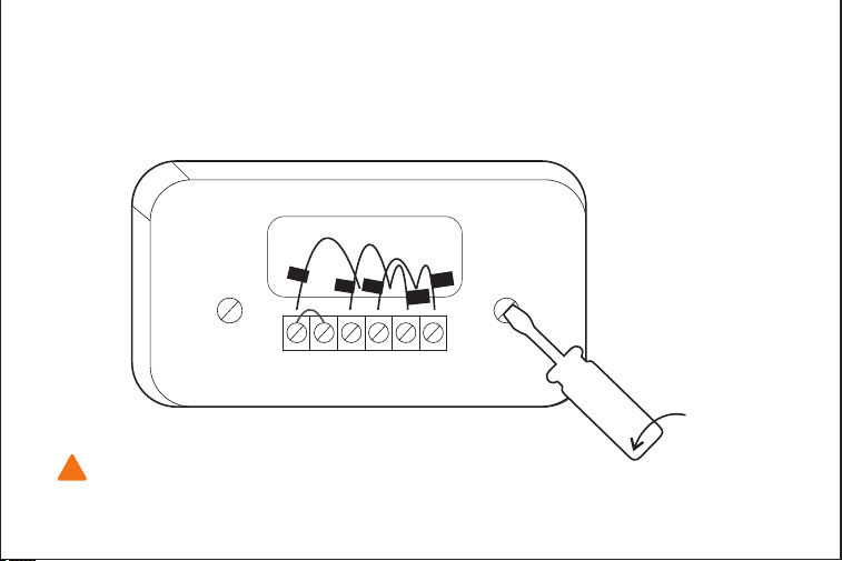
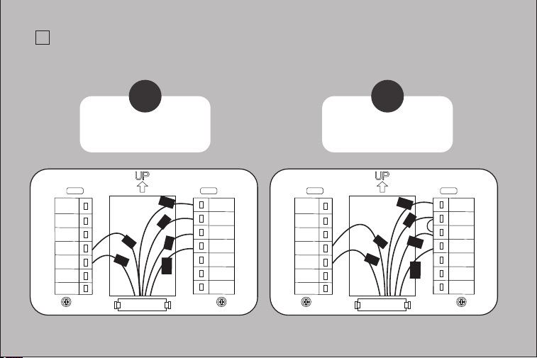
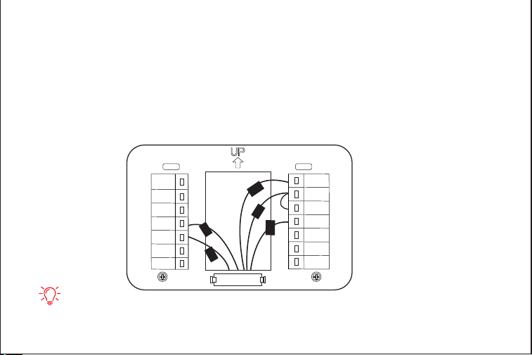
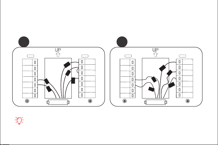
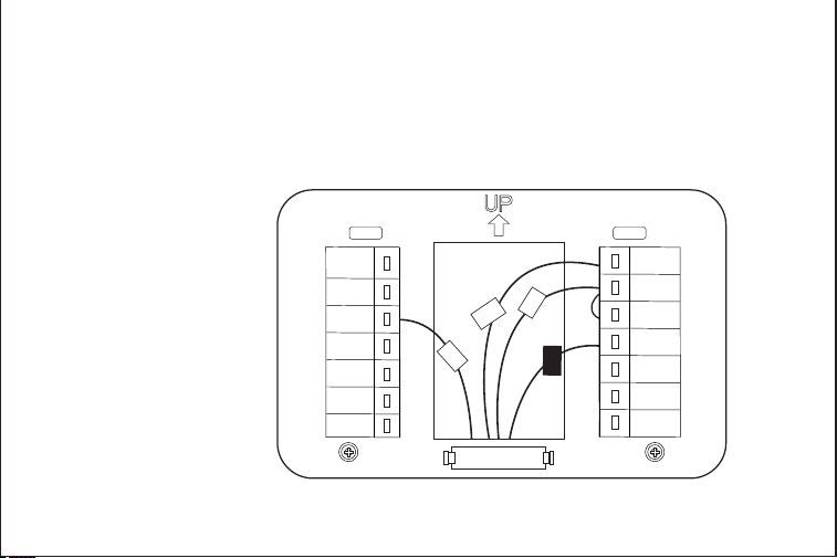
STEP13
First, connect these 3 wires as show: RC,C,S. Then connect any remaining
wires to their corresponding terminal.
TIPS:
1.Press the terminal block levers to insert the wires more easily.
2.When a wire has been connected correctly, the level on the block will lower.
RC
C
S
5150
W
1
W/
STEP14
Gently press your thermostat into the backplate until it “clicks” into place.
TIPS:
If the thermostat “rocks”or is not flush with the wall,be sure the excess wires are
pushed all the way into the wall.
A1
C
RC
RH
W1
W2
AC+
AC-
RT+
RT-
S
G
Y1
Y2
O/B
STEP13
First, connect these 3 wires as show: RC,C,S. Then connect any remaining
wires to their corresponding terminal.
TIPS:
1.Press the terminal block levers to insert the wires more easily.
2.When a wire has been connected correctly, the level on the block will lower.
RC
C
S
5150
W
1
W/
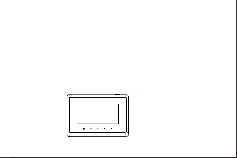
STEP14
Gently press your thermostat into the backplate until it “clicks” into place.
TIPS:
If the thermostat “rocks”or is not flush with the wall,be sure the excess wires are
pushed all the way into the wall.
A1
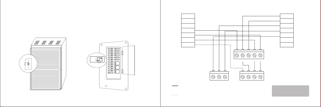
STEP15
Turn the power to your HVAC system back on using the master switch or at the
circuit breaker box.
ON
OFF
ON
OFF
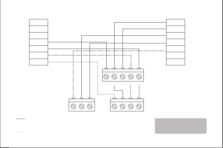
Boiler or radiant system with air handler and conventional cooling or heat pump.
C
RC
RH
W1
W2
AC+
AC-
Y1Y2RCG
Air handler
Y1Y2CO/B
Air conditioner or
Heat pump
W1RW2
Boiler
Stage 2 heat and
cool if applicable
*Reversing valve
for heat pumps only
Note:
Do not jumper RC or RH
RT+
RT-
S
G
Y1
Y2
O/B
5352
A1
STEP15
Turn the power to your HVAC system back on using the master switch or at the
circuit breaker box.
ON
OFF
ON
OFF
Boiler or radiant system with air handler and conventional cooling or heat pump.
C
RC
RH
W1
W2
AC+
AC-
Y1Y2RCG
Air handler
Y1Y2CO/B
Air conditioner or
Heat pump
W1RW2
Boiler
Stage 2 heat and
cool if applicable
*Reversing valve
for heat pumps only
Note:
Do not jumper RC or RH
RT+
RT-
S
G
Y1
Y2
O/B
5352
A1
RT+
RT-
S
G
Y1
Y2
O/B
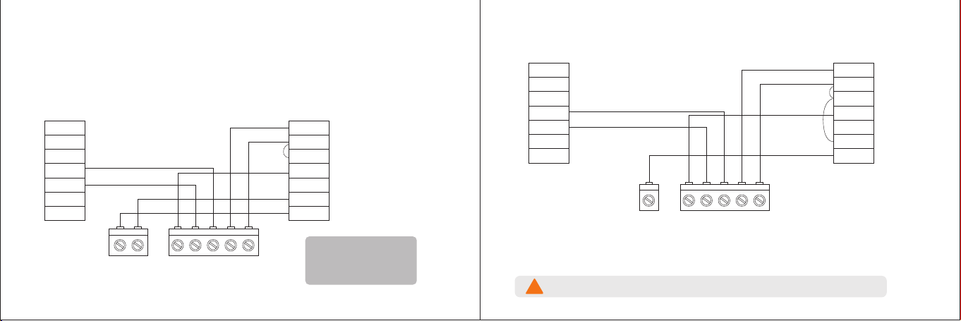
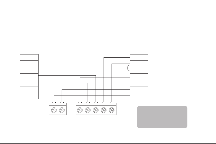
Accessory devices
The T29 can control an accessory HVAV device like a humidifier, dehumidifier, or
ventilation device from its AC terminals
Note:You will need to configure the accessory device when you first power on your T29.
2-wire accessory (ventilator)
C
RC
RH
W1
W2
AC+
AC-
RCGYWWire1 Wire2
Furnace control board
Accessory
RT+
RT-
S
G
Y1
Y2
O/B
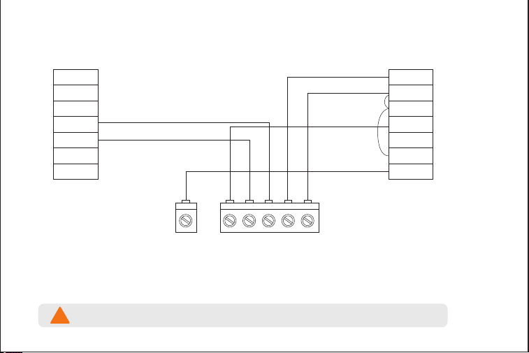
1-wire accesory
(ventilator)
C
RC
RH
W1
W2
AC+
AC-
RCGYWWire1
Furnace control board
Accessory
T29 automatically connects Rc to AC- when 1-wire configuration is selected during
accessory setup.
Warning: Damage may occur if accessory is connected to AC-
!
5554
Note:
Do not jumper RH or AC+
A1
RT+
RT-
S
G
Y1
Y2
O/B
Accessory devices
The T29 can control an accessory HVAV device like a humidifier, dehumidifier, or
ventilation device from its AC terminals
Note:You will need to configure the accessory device when you first power on your T29.
2-wire accessory (ventilator)
C
RC
RH
W1
W2
AC+
AC-
RCGYWWire1 Wire2
Furnace control board
Accessory
RT+
RT-
S
G
Y1
Y2
O/B
1-wire accesory
(ventilator)
C
RC
RH
W1
W2
AC+
AC-
RCGYWWire1
Furnace control board
Accessory
T29 automatically connects Rc to AC- when 1-wire configuration is selected during
accessory setup.
Warning: Damage may occur if accessory is connected to AC-
!
5554
Note:
Do not jumper RH or AC+
A1
C
RC
RH
W1
W2
AC+
AC-
RT+
RT-
S
G
Y1
Y2
O/B
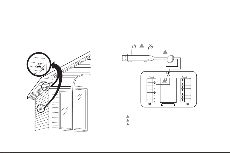
1.Wire the NTK100 Outdoor Sensor to the RT+/RT- terminals on the thermostat. If the lead wire provided with
the NTC-100K is not long enough, run cable to a hole at the selected NTC-10Klocation.Color-coded,18-gauge
thermostatwireisrecom-mended. ForanexampleofgeneralwiringoftheNTC-100K,seeFig.2.Pigtailwiring
canbeused.
2.MounttheNTC-100Kinitsmountingclip.
3.Plugwiringholeusingnonhardeningcaulkorputty.
Fig.1. Typical locations for outdoor sensor.
Fig. 2. Wiring diagram for the NTC-100K
Outdoor Sensor to the thermostat.
Wiring must comply with applicable codes, ordinances and regulations.
WIRING HOLE
THROUGH
STRUCTURE
NTC-100K
1
Use appropriate mounting means for the type of structure.
1
2
2
3
Plug wiring hole with non- hardening caulk or putty.
RT+/RT- terminal location varies with model.
Optional sensor
SASWELL NTC 100K Room Sensor With 3 Meter Wiring
*Used for outdoor temperature detection when there is water pump
protection.
5756
3
A1
C
RC
RH
W1
W2
AC+
AC-
RT+
RT-
S
G
Y1
Y2
O/B
1.Wire the NTK100 Outdoor Sensor to the RT+/RT- terminals on the thermostat. If the lead wire provided with
the NTC-100K is not long enough, run cable to a hole at the selected NTC-10Klocation.Color-coded,18-gauge
thermostatwireisrecom-mended. ForanexampleofgeneralwiringoftheNTC-100K,seeFig.2.Pigtailwiring
canbeused.
2.MounttheNTC-100Kinitsmountingclip.
3.Plugwiringholeusingnonhardeningcaulkorputty.
Fig.1. Typical locations for outdoor sensor.
Fig. 2. Wiring diagram for the NTC-100K
Outdoor Sensor to the thermostat.
Wiring must comply with applicable codes, ordinances and regulations.
WIRING HOLE
THROUGH
STRUCTURE
NTC-100K
1
Use appropriate mounting means for the type of structure.
1
2
2
3
Plug wiring hole with non- hardening caulk or putty.
RT+/RT- terminal location varies with model.
Optional sensor
SASWELL NTC 100K Room Sensor With 3 Meter Wiring
*Used for outdoor temperature detection when there is water pump
protection.
5756
3
A1