5/2 minute selectable minimum Run/Off time provides short cycle and compressor protection
CAUTION:
The TX9000TS is protected against normal static electric discharges. However, in extremely dry weather you should touch a grounded metal object before the TX9000TS to minimize the risk of causing damage to the unit.
Your thermostat is a precision instrument. Please handle it with care.
COMPATIBILITY
The TX9000TS can be used with most 24 volt gas, oil or electric heating and air conditioning systems, single stage heat pumps or gas millivolt heating systems. It cannot be used with 3 wire zone valves, 120V systems, or multistage systems.
INSTALLATION
Please read all instructions carefully before beginning installation.
WARNING:
Your thermostat is a precision instrument. Please handle it with care.
All wiring must conform to local codes and ordinances.
Turn off electricity to the appliance before installing or servicing thermostat or any part of the system. Do not turn electricity back on until work is completed.
This thermostat is designed for use with 24 volt and millivolt systems. The thermostat should be limited to a maximum of 1.5 amps; higher amperage may cause damage to the thermostat.
Do not short (jumper) across electric terminals at control on furnace or air conditioner to test the system. This will damage the thermostat and void your warranty.
TOOLS REQUIRED
#1 Phillips screwdriver (small)
Drill with 3/16-in. (4.8mm) bit
Wire stripper/cutter
LOCATION
On replacement installations, mount the new thermostat in place of the old one unless the conditions listed below suggest otherwise. On new installations, follow the guidelines listed below.
Locate the thermostat on an inside wall, about 5 ft. (1.5m) above the floor, in a room that is used often.
Do not install it where there are unusual heating conditions, such as: in direct sunlight; near a lamp, radio, television, radiator, register, or fireplace; near hot water pipes in a wall; near a stove on the other side of a wall.
Do not locate in unusual cooling conditions, such as: on a wall separating an unheated room; or in a draft from a stairwell, door, or window.
Do not locate in a damp area. This can lead to corrosion that will shorten thermostat life.
Do not locate where air circulation is poor, such as: in a corner or an alcove; or behind an open door.
Do not install the unit until all construction work and painting has been completed.
CAUTION:
Read instructions carefully before removing any wiring from existing thermostat.
Wires must be labeled before they are removed.
Do not allow wires to touch each other or parts on thermostat.
When removing wires from their terminals, ignore the color of the wires since they may not comply with any standard.
REMOVING THE OLD THERMOSTAT
1. Switch electricity to the furnace and air conditioner OFF; then proceed with the following steps.
2. Remove cover from old thermostat. Most are snap-on types and simply pull off. Some have locking screws on the side; these must be loosened.
3. Note the letters printed near the terminals. Attach labels (enclosed) to each wire for identification. Remove and label wires one at a time. Make sure the wires do not fall back inside the wall.
4. Loosen all screws on the old thermostat and remove it from the wall.
MOUNTING THE TX9000TS
5. Strip insulation leaving 3/8 in. (9.5mm) bare wire ends and clean off any corrosion.
6. Fill wall opening with non-combustible insulation to prevent drafts from affecting the thermostat.
CAUTION: Be careful not to drop the body or disturb electronic parts. Leave the cover closed while the body is being removed from the base.
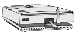
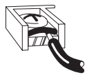
7. Press up on the thumb latch at the bottom of thermostat and separate the body from its base.
8. Hold the base against the wall. Route the wires through the hole below the terminal block. Position the base for best appearance (to hide any marks from an old thermostat). Attach the base to the wall with the two screws provided.
NOTE: If you are mounting the base to a soft material like plasterboard or if you are using the old mounting holes, the screws may not hold. Drill a 3/16-in. (4.8mm) hole at each screw location, and insert the plastic anchors provided. Then mount the base as described below.
CONNECTING THE WIRES
9. Loosen wire clamp screws just enough to slide wire under the black top part of the clamp.
10. Using your label, and diagrams below determine appropriate wiring for you system.
11. If you are unsure or need assistance, call the LUX Technical Assistance Dept. (see technical assistance.)
12. Slide proper wire between the brass back and black top clamp.
13. Tighten each screw securely.
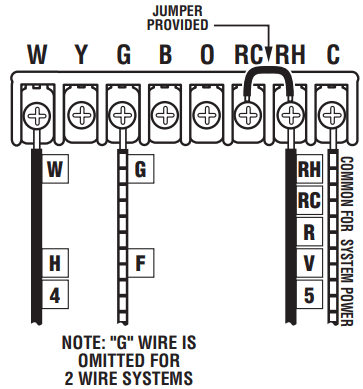
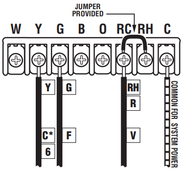
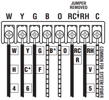
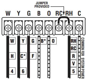
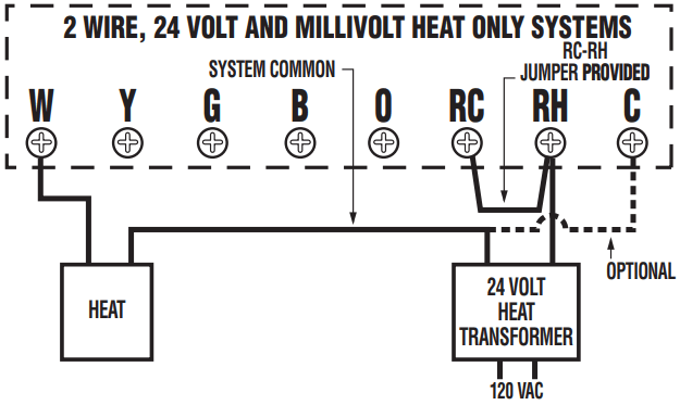
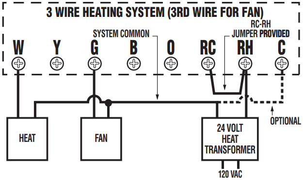
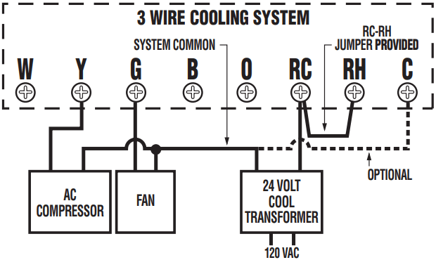
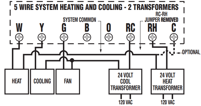
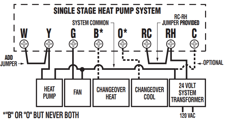
WIRING DIAGRAMS
2 + 3 WIRE HEATING SYSTEMS
COOLING SYSTEMS
HEATING/COOLING SYSTEMS 5 + 6 Wire 2 Transformers
HEATING/COOLING SYSTEMS 4 + 5 Wire 1 Transformers
WIRING DIAGRAM NOTES (APPLIES TO ALL DRAWINGS)
The DASHED lines are optional depending upon your system type.
Verify whether “C”, “X” or “B” wires are connected to system common.
If “B” and “O” are both present, it is likely that “B” is a system common.
If a “B” wire in your system is a common, then connecting it to the “B” terminal may cause damage to your system.
If “Y” and “C” are both present, it is likely that “C” is a system common.
Use an optional common wire to allow the system to power your thermostat.
The DASHED wires are optional depending on your system type.
Verify whether “C”, “X” or “B” wires are connected to system common.
If “B” and “O” are both present, it is likely that “B” is a system common.
If a “B” wire in your system is a common, then connecting it to the “B” terminal may cause damage to your system.
If “Y” and “C” are both present, it is likely that “C” is a system common.
Use an optional common wire to allow the system to power your thermostat.
COMPLETING YOUR INSTALLATION
14. Install two(2) Energizer or DURACELL "AA" size alkaline batteries at this time. For instructions, see "BATTERIES & MAINTENANCE".
15. Initially, your thermostat will display "SUN 12:00 AM". To correct the display, refer to "Setting the DAY and TIME" in the "OPERATING INSTRUCTIONS" section of this manual.
16. Install your TX9000TS on its base. To do this hang the top of the unit by the tabs on the base, then snap the bottom of the unit into place. Do not use unnecessary force. If the body does not snap into place easily, remove the body, re-hang it from the tabs and try again.
17. Turn the power back on to your heating and/or air conditioning system.
18. Verify that the system and its fan are operating properly. When set to a high temperature, the heating system should provide warm air after a short time. Likewise a cooling system should provide cool air after a short time. Usually sound from the furnace and air conditioning units can be heard while they are running. The rush of moving air should be heard within a short time after either has been started.
NOTE: If you have an electric heat system and the blower does not operate after installation, see figure in SETUP OPTIONS Section to find the electric/gas heat jumper on the back of the body. Move the jumper to the ELEC position.
19. Your installation is now complete.
OPERATING INSTRUCTIONS
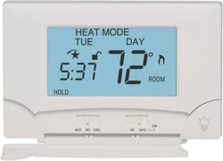
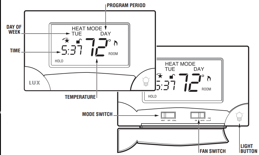
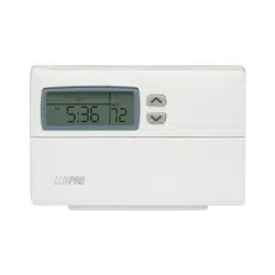
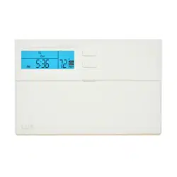
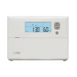
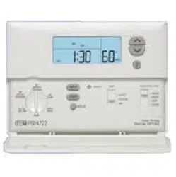
The TX9000TS displays the current time and the room temperature. It also displays the day of the week and the current program period, MORN, DAY, EVE, or NITE. Temperature is indicated near the center of the display, and time is indicated on the left. Setting and program changes can be made with the thermostat body on the wall, or removed from its base plate.
SYSTEM MODE SWITCH
The SYSTEM MODE SWITCH has three positions HEAT, OFF and COOL. Each sets the corresponding operating mode. In the winter, set the system switch to HEAT to control your heating system. In the summer, set the switch to COOL to control your air conditioner. In spring and fall or when the windows are open, you can set the switch to OFF. When thermostat is in the OFF position, neither HEAT or COOL programs will run.
FAN MODE SWITCH
The fan switch has two positions; AUTO will only run your system’s fan as required for heating and cooling. ON runs your system’s fan continuously.
UP/DOWN CHANGE ARROW KEYS
While operating the TX9000TS there will often be two arrow keys visible (just to the right of the temperature) one pointing up and the other pointing down. They are used to adjust temperatures and change other settings.
TEMPERATURE ADJUSTMENT
Touch the displayed temperature once then touch the UP/DOWN arrow key; it adjusts the flashing set temperature by one degree in the associated direction. Holding the key will automatically advance the setting in the associated direction. For simple operation see HOLD.
CHANGING OTHER SETTINGS
If there are many choices for a value, usually that setting will automatically advance by holding one of the arrow keys. Some settings though, must be changed one touch at a time.
NAVIGATION KEYS
MENU: Touch this key to begin viewing available menus.
SCROLL: Use this key to see the available menu choices.
YES: Touch this key to enter a menu. When present on a menu, touching this key accepts any setting changes you have made.
NOTE: Neglecting to accept changes by touching this key when present, will leave the unit at its previous setting.
EXIT: Touch this key to return to the main operating screen.
DISPLAY ILLUMINATION
Press the light bulb button at the lower right corner of the body to illuminate the display. It will remain illuminated for 15 seconds. Touching a field in the screen extends illumination time.
AUDIBLE BEEP
The TX9000TS will emit an audible beep to acknowledge that a field in the screen has been touched.
ICONS
FLAME ICON
In HEAT mode a FLAME icon will be visible to the right of the current room temperature. While heating is active, the FLAME will flash.
SNOWFLAKE ICON
In COOL mode a SNOWFLAKE icon will be visible to the right of the current room temperature. While cooling is active, the SNOWFLAKE will flash.
LOW BATTERY ICON
When the Low Battery level has been reached, the battery icon will appear. It will disappear only when fresh batteries have been installed.
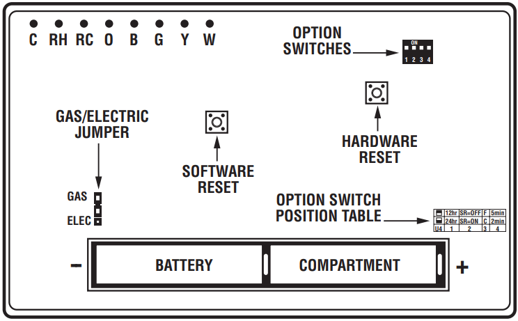
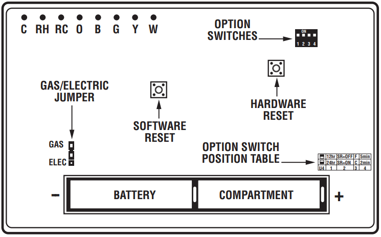
HARDWARE RESET
This button will unlock the touchscreen and read option switch positions before the unit resumes normal operation. Programs and other settings will be maintained.
SOFTWARE RESET
This reset is disabled while the touchscreen is locked. When activated it will reset all programmable values and settings including the lock code and clock, to their default values. Then option switch positions will be read before resuming normal operation. Record your settings and programs before pressing this button.
NOTE:
Take care not to inadvertently press the SOFTWARE RESET button while programming your unit.
Performing a SOFTWARE RESET will reprogram all software settings to their default values.
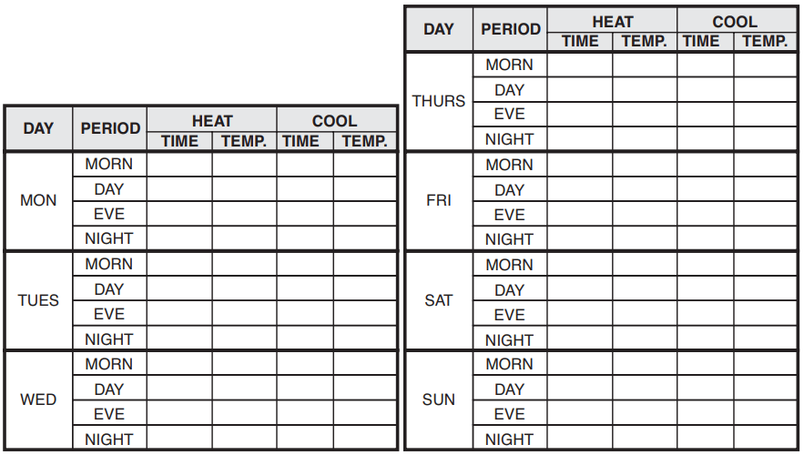
Copy your programs into the blank chart before using SOFTWARE RESET to assist reprogramming.
SETTING THE DAY AND TIME
SET DAY: Touch displayed DAY, advance with UP arrow.
Touch displayed DAY again to return to main screen.
SET TIME: Touch displayed time, set with UP or DOWN arrows. Touch displayed time again to return to main screen.
DAY and TIME may also be set from their menu as follows:
Touch MENU. You should see Set Day/Time displayed.
Touch YES and day of the week will flash.
Touch UP ARROW to advance to set the day.
Touch YES to accept displayed week day and advance to SET TIME. Or touch NEXT to advance to set current time without accepting changes. Time will be flashing.
Touch UP/DOWN ARROW to set the current time of day.
Touch YES to accept displayed time.
Touch EXIT to return to the main screen, or touch NEXT to rotate back to SET THE DAY.
TEMPORARY TEMPERATURE OVERRIDE
Temporary temperature override allows you to change the current Set Temperature in Heat or Cool until the next program period without changing your temperature control programs.
Touch displayed temperature; the screen will flash your SET TEMPERATURE. UP/DOWN arrows will become visible.
Use UP/DOWN arrows to change the temperature setting while it is flashing. OVERRIDE will be indicated at the top of the display.
OVERRIDE will be automatically canceled at the start of the next program period.
OVERRIDE will be cancelled if the set temperature is adjusted to its programmed value or if the units mode is changed.
TEMPERATURE HOLD
HOLD may be used for manual temperature control. It is the simplest means to set and maintain a fixed temperature in Heat or Cool, without concern for programming.
Touching HOLD toggles the unit into or out of the hold mode with the current status indicated in the display. In HOLD adjust temperature as desired.
Temperature settings will only change manually while HOLD is active. To clear hold, touch HOLD again.
PROGRAMMING
The TX9000TS provides four independent programming periods per day. Heat and Cool are programmed separately. You can use the default programs or alter them to suit your schedule.
DEFAULT ENERGY STAR® TEMPERATURE PROGRAMS
To review the programs select Heat or Cool mode, touch MENU and then use SCROLL to see HEAT or COOL PROGRAM. Touch YES to enter HEAT or COOL PROGRAM. Use NEXT to step through each period and its set temperature. You can use the built-in programs as shown, or change them as you wish. Touch EXIT to return to the main display. Each day is divided into four periods. Each period has its own starting time and temperature.
The default programs are given in the following table:
PERIOD
HEAT MODE
COOL MODE
MORN
6:00 AM 700 F (210 C)
6:00 AM 780 F (260 C)
DAY
8:00 AM 620 F (170 C)
8:00 AM 850 F (290 C)
EVE
6:00 PM 700 F (210 C)
6:00 PM 780 F (260 C)
NITE
10:00 PM 620 F (170 C)
10:00 PM 820 F (280 C)
Pressing the S. RESET button restores these heating and cooling programs and all other default settings.
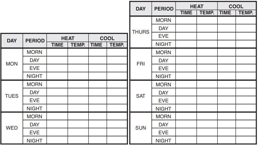
PROGRAMMING THE UNIT
You can change any preset times and/or temperatures to suit your schedules for HEAT and COOL during each period of each day of the week. A blank programming chart is provided for you to record your temperature settings in that chart.
Set the mode switch to HEAT to program the unit for controlling your heater. Set the mode switch to COOL to program the unit for controlling your air conditioner.
Touch MENU.
Use SCROLL to advance to SET/REVIEW HEAT PROGRAMS or SET/REVIEW COOL PROGRAMS.
Touch YES to begin scrolling through the HEAT or COOL settings.
Use the UP/DOWN ARROW to change the flashing start time for MON MORN. One period ends at the start time of the next period. The beginning of a period may not be any closer to the beginning of the next period than one 15 minute increment.
Touch YES to accept the displayed start time and advance to program its set temperature.
Use UP/DOWN ARROW to change the flashing temperature setting for MON MORN.
Touch YES to accept the displayed temperature and advance to Set MON DAY start time.
Use the UP/DOWN ARROW to change the flashing start time for MON DAY.
Touch YES to accept the displayed value and advance to program temperature.
Use UP/DOWN ARROW to change the flashing temperature setting for MON DAY.
Touch YES to accept the displayed temperature and advance to Set MON EVE start time.
Use the UP/DOWN ARROW to change the flashing start time for MON EVE.
Touch YES to accept the displayed value and advance to program temperature.
Use UP/DOWN ARROW to change the flashing temperature setting for MON EVE.
Touch YES to accept the displayed temperature and advance to Set MON NITE start time.
Use the UP/DOWN ARROW to change the flashing start time for MON NITE.
Touch YES to accept the displayed value and advance to program temperature.
Use UP/DOWN ARROW to change the flashing temperature setting for MON NITE.
Touch YES to accept the displayed temperature and advance to Set TUE MORN start time.
Continue programming for each day of the week.
Touch EXIT to return to main screen.
TIP: Pressing Day, Time or Temperature while programming will shift focus to that setting, allowing it to be edited in the order most convenient for you.
COPY
COPY will copy the previous days programs into the current day and advance the thermostat to the beginning of next day.
ADVANCED FEATURES
FILTER USAGE MONITOR
The FILTER MONITOR is used to help determine when your filter should be changed. It counts the hours of HEAT and COOL since it was last reset When the monitor limit is reached the CHANGE FILTER indicator will become visible. The default value of 720hrs is normally used for a 90 day filter. Other values are given in the following table.
FILTER LIFE IN DAYS
SET COUNTER HOURS TO
30
240
60
480
90
720
To Reset Filter Counter And/Or Change The Counter Limit
At the main menu touch MENU.
SCROLL to FILTER USAGE.
Touch YES. Filter Usage Count will appear.
Touch NEXT. RESET will show.
Touch YES to reset the counter and advance to the filter limit menu, or touch NEXT to advance to the filter monitor menu without resetting the counter. Limit Hours will be flashing.
Use UP/DOWN arrows to change limit. Set the filter limit to "0" to disable the Filter Usage Monitor.
Touch YES to accept new count value and return to the filter counter menu. If a new limit is set, the filter counter will be reset automatically.
Touch EXIT to return to main menu.
SWING SETTING
A thermostat works by turning your heating or cooling system on and off whenever the room temperature varies a certain number of degrees from the set-point temperature. This variation is the "swing." Your system should cycle on about 3 to 6 times per hour. A smaller swing number increases the number of cycles, so room temperature is more constant. A larger swing number decreases the number of cycles, saving energy in most cases. To change the SWING value from the main menu:
Touch MENU.
SCROLL to SWING VALUE.
Touch YES. Adjust Swing Value will appear.
Use UP/DOWN arrows to adjust.
Touch EXIT to return to main display.
TEMPERATURE CALIBRATION
From the main menu touch MENU.
SCROLL to CAL TEMP.
Touch YES. CAL TEMP will be visible and adjustment value will be flashing.
Use UP/DOWN arrows to adjust offset value.
Touch EXIT to return to the main screen.
ENERGY USAGE MONITOR
A timer in the unit records your system’s ON time for each mode of the current day, previous day, and cumulative total to let you see the effects of your temperature settings and weather conditions.
Select HEAT to monitor heating energy usage or COOL to monitor cooling usage. To view ENERGY/USAGE
From the main menu touch MENU.
SCROLL to ENERGY USAGE.
Touch YES. The current day’s ENERGY USAGE will be displayed.
Touch NEXT to view yesterday’s energy use.
Touch NEXT to advance to total ENERGY usage since the Monitor was last set to zero.
Touch NEXT to display "000". Touching NEXT will toggle between the counter value and "000".
Touch YES to accept the current display value as the counter value. Use "000" to effect a reset.
Touch EXIT to return to the main screen.
PROGRAM LOCK
The Program Lock allows the owners/operators to prevent unauthorized changes to the thermostat’s settings. When the thermostat is locked, a three digit code is set (000 to 999). That code must be re-entered before locked settings can be changed without performing a hardware reset of the unit. The status of the lock is indicated by an open or closed padlock icon.
TO SET CODE
From the main menu touch MENU.
SCROLL to SET KEYBOARD LOCK.
Touch YES. ENTER OLD CODE and both open and closed padlock icons will be displayed. The default code is "000".
Hold UP/DOWN arrows to count to code number.
Touch YES. ENTER NEW CODE will appear.
Hold UP/DOWN arrows to count to code number (Record Code Number).
Touch YES to accept new code; ENTER OLD CODE will be visible.
Touch EXIT to return to main display.
TO LOCK SETTINGS
Touch OPEN LOCK SYMBOL on display LOCK KEY? will appear.
Touch YES. The display will now show a CLOSED PADLOCK.
TO UNLOCK SETTINGS
Touch the CLOSED PADLOCK. UNLOCK KEY? is displayed.
Touch YES. ENTER LOCK CODE will be displayed.
Hold UP/DOWN arrows to count to code number.
Touch YES to enter code. The OPEN LOCK symbol will now be displayed in the display.
If you forget your code and the touch screen is locked, perform a Hardware Reset to unlock it. With the touch screen unlocked, you may perform a Software Reset to reset the code to "000". See "Hardware Reset" and "Software Reset".
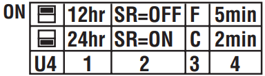
SETUP OPTIONS
There are Installation Option switches located inside the thermostat on the rear of its circuit board. They control the following:
TIME DISPLAY FORMAT 12/24 SWITCH #1
The position of this switch controls whether the time is displayed in 12 hour or 24 hour Military Time format.
SMART RECOVERY SWITCH #2
Smart Recovery allows your HVAC system to attempt to recover from a setback period and reach your desired comfort temperature set point by the beginning of your programmed comfort period. This option allows you to choose whether to use Smart Recovery.
When enabled, Smart Recovery will initiate if:
Recovery is from an evening setback to morning comfort or day setback to evening comfort period.
In Heat mode the temperature set point of the comfort period must be higher than the setback period.
In Cool mode the temperature set point of the comfort period must be lower than the setback period.
The estimated Smart Recovery time must be longer than 15 minutes for a Smart recovery to be initiated.
Maximum Smart Recovery time is one hour.
The Smart Recovery temperature set point must be achievable. If a desired smart recovery is repeatedly ignored by your thermostat. That is an indicator that you should modify your program so that the recovery can be achieved within the 1 hour limit.
A Smart Recovery may not be initiated for 48 hours after the units programs have been changed. This allows the unit to gather the data necessary to predict a Smart Recovery time.
TEMPERATURE DISPLAY FORMAT ˚F/˚C SWITCH #3
The position of this switch controls whether the temperature is displayed in degrees ˚F or ˚C.
5 MIN / 2 MIN MINIMUM RUN TIME SWITCH #4
The position of this switch controls minimum length of time the thermostat must remain with Heat or Cool either ON or OFF before it will automatically switch to the alternate ON or OFF state. This feature prevents short cycling and provides compressor protection for cooling units. Choices are 2 or 5 minutes.
REPOSITIONING SWITCHES
Use this table to determine the positions which correspond to the operation you prefer.
This table is printed on the circuit board. To change a switch position move switch down or up. After settings have been changed with batteries installed, press the Hardware Reset (H.W. Reset) button on the rear of the unit's circuit board for changes to take effect.
GAS/ELECTRIC JUMPER
In HEAT mode, the position of this jumper controls when the thermostat requests the system fan to run. In Gas mode the fan is normally controlled by the heating system itself. In Electric mode, the fan is controlled by the thermostat.
BATTERIES AND MAINTENANCE
The TX9000TS requires batteries to operate your heating/cooling system. Replace the batteries when the battery REPLACE indicator appears in the display or at least once a year.
To access your units batteries remove the unit from the wall by pressing up on the thumb latch at the bottom of thermostat and swinging the body up and away to remove it from the wall.
Remove the used batteries.
Install two new Energizer® or DURACELL® "AA" size alkaline batteries in the battery compartment. Observe the polarity marking shown in the compartment.
Hang the top of the unit by the tabs at the top corners of the base, then snap the bottom of the unit into place. Do not use unnecessary force. If the body does not snap into place easily, remove the body, re-hang it from the tabs and try again.