
Loading ...
Loading ...
Loading ...
W415-2367 / B / 12.09.20
94
FR
exigences d'évacuation
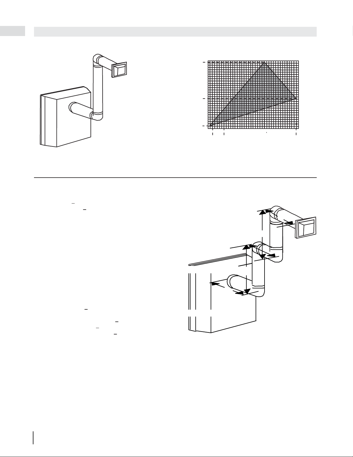
Configuration d'évacuation simple
(deux coudes de 90° seulement)
Consultez le graphique pour déterminer la course verticale
nécessaire V
T
par rapport à la course horizontale requise H
T
.
COURSE
VERTICALE
REQUISE
EN PIEDS
(MÈTRES) V
T
LONGUEUR DES COURSES HORIZONTALES PLUS
LES DÉVIATIONS EN PIEDS (MÈTRES) H
T
La section ombragée à l'intérieur des lignes représente
des valeurs acceptables pour H
T
et V
T
90°
V
1
V
2
H
1
H
2
90°
90°
90°
H
3
(H
T
) > (V
T
)
16.3_2C
4,2 (1,3)
8,3 (2,54)
12,5 (3,8)
0
2,5
(0,8)
5
(1,5)
7,5
(2,3)
10
(3,1)
12,5
(3,8)
15
(4,6)
17,5
(5,3)
20
(6,1)
12,25 (3,7)
1 (0,3)
5,5
(1,68)
1
(0,3)
3,5
(1,1)
19,25
(5,9)
Lorsque la configuration de l'évacuation exige plus qu'un coude de 90°, les formules suivantes
s'appliquent :
Formule 1 : H
T
< 3,5V
T
Formule 2 : H
T
+ V
T
< 24,75 pieds (7,5m)
Exemple :
V
1
= 4 PI (1,2m)
V
2
= 1,5 PI (0,5m)
V
T
= V
1
+ V
2
= 4PI (1,2m) + 1,5PI (0,5m) = 5,5 PI (1,7m)
H
1
= 2 PI (0,6m)
H
2
= 1 PI (0,3m)
H
3
= 1 PI (0,3m)
H
4
= 1,5 PI (0,5m)
H
R
= H
1
+ H
2
+ H
3
+ H
4
= 2PI(0,6m) + 1PI(0,3m) + 1PI(0,3m) + 1,5PI(0,5m) = 5,5PI(1,7m)
H
O
= 0,03 (quatre coudes 90° + un coude 45° - 90°)
= 0,03 (90 + 90 + 90 + 90 + 45 - 90) = 9,45 PI (2,9m)
H
T
= H
R
+ H
O
= 5,5PI (1,7m) + 9,45PI (2,9m) = 14,95PI (4,6m)
H
T
+ V
T
= 14,95PI (4,6m) + 5,5PI (1,7m) = 20,45PI (6,2m)
Formule 1 : H
T
< 3,5V
T
3,5V
T
= 3,5PI (1,1m) x 5,5PI (1,7m) = 19,25PI (5,9m)
14,95 PI (4,6m) < 19,25 PI (5,9m)
Formule 2 : H
T
+ V
T
< 24,75 PI (7,5m)
20,45 PI (6,2m) < 24,75 PI (7,5m)
Puisque les deux formules sont respectées, cette configuration d'évacuation est acceptable.
50 (1270)
100 (2540)
150(3810)
(H
T
) < (V
T
)
Simple venting configuration
(only one 90° elbow)
See graph to determine the required vertical rise V
T
for the required horizontal run H
T
.
0
2.5
(0.8)
5
(1.5)
7.5
(2.3)
10
(3.1)
12.5
(3.8)
15
(4.6)
40 (12.2)
10 (3.1)
20 (6.1)
30 (9.1)
17.5
(5.3)
20
(6.1)
39 (11.9)
HORIZONTAL VENT RUN PLUS OFFSET IN
FEET (METERS) H
T
For vent configurations requiring more than one 90° elbow, the following formulas apply:
Formula 1: H
T
< V
T
Formula 2: H
T
+ V
T
< 40 feet (12.2m)
Example 1:
V
1
= 3 FT (0.9m)
V
2
= 8 FT (2.4m)
V
T
= V
1
+ V
2
= 3FT (0.9m) + 8FT (2.4m) = 11FT (3.4m)
H
1
= 2.5 FT (0.8m)
H
2
= 2 FT (0.6m)
H
R
= H
1
+ H
2
= 2.5FT (0.8m) + 2FT (0.6m) = 4.5 FT (1.4m)
H
O
= .03 (three 90° elbows - 90°) = .03 (270° - 90°) = 5.4 FT (1.6m)
H
T
= H
R
+ H
O
= 4.5FT (1.4m) + 5.4FT (1.6m) = 9.9 FT (3m)
H
T
+ V
T
= 9.9FT (3m) + 11FT (3.4m) = 20.9FT (6.4m)
Formula 1: H
T
< V
T
9.9FT (3m) < 11FT (3.4m)
Formula 2: H
T
+ V
T
< 40 FT (12.2m)
20.9FT (6.4m) < 40 FT (12.2m)
Since both formulas are met, this vent configuration is acceptable.
90°
90°
90°
V
1
V
2
H
1
H
2
The shaded area within the lines represents
acceptable values for H
T
and V
T
0
2.5
(0.8)
5
(1.5)
7.5
(2.3)
10
(3.1)
12.5
(3.8)
15
(4.6)
40 (12.2)
10 (3.1)
20 (6.1)
30 (9.1)
17.5
(5.3)
20
(6.1)
39 (11.9)
GD36
BGD36
REQUIRED
VERTICAL
RISE IN FEET
(METERS)V
T
HORIZONTAL VENT RUN PLUS OFFSET IN
FEET (METERS) H
T
16.2B
REQUIRED
VERTICAL
RISE IN FEET
(METERS)V
T
0
2.5
(0.8)
5
(1.5)
7.5
(2.3)
10
(3.1)
12.5
(3.8
(H
T
) < (V
T
)
Simple venting configuration
(only one 90° elbow)
See graph to determine the required vertical rise V
T
for the required horizontal run H
T
.
0
2.5
(0.8)
5
(1.5)
7.5
(2.3)
10
(3.1)
12.5
(3.8)
15
(4.6)
40 (12.2)
10 (3.1)
20 (6.1)
30 (9.1)
17.5
(5.3)
20
(6.1)
39 (11.9)
HORIZONTAL VENT RUN PLUS OFFSET IN
FEET (METERS) H
T
For vent configurations requiring more than one 90° elbow, the following formulas apply:
Formula 1: H
T
< V
T
Formula 2: H
T
+ V
T
< 40 feet (12.2m)
Example 1:
V
1
= 3 FT (0.9m)
V
2
= 8 FT (2.4m)
V
T
= V
1
+ V
2
= 3FT (0.9m) + 8FT (2.4m) = 11FT (3.4m)
H
1
= 2.5 FT (0.8m)
H
2
= 2 FT (0.6m)
H
R
= H
1
+ H
2
= 2.5FT (0.8m) + 2FT (0.6m) = 4.5 FT (1.4m)
H
O
= .03 (three 90° elbows - 90°) = .03 (270° - 90°) = 5.4 FT (1.6m)
H
T
= H
R
+ H
O
= 4.5FT (1.4m) + 5.4FT (1.6m) = 9.9 FT (3m)
H
T
+ V
T
= 9.9FT (3m) + 11FT (3.4m) = 20.9FT (6.4m)
Formula 1: H
T
< V
T
9.9FT (3m) < 11FT (3.4m)
Formula 2: H
T
+ V
T
< 40 FT (12.2m)
20.9FT (6.4m) < 40 FT (12.2m)
Since both formulas are met, this vent configuration is acceptable.
90°
90°
90°
V
1
V
2
H
1
H
2
The shaded area within the lines represents
acceptable values for H
T
and V
T
0
2.5
(0.8)
5
(1.5)
7.5
(2.3)
10
(3.1)
12.5
(3.8)
15
(4.6)
40 (12.2)
10 (3.1)
20 (6.1)
30 (9.1)
17.5
(5.3)
20
(6.1)
39 (11.9)
GD36
BGD36
REQUIRED
VERTICAL
RISE IN FEET
(METERS)V
T
HORIZONTAL VENT RUN PLUS OFFSET IN
FEET (METERS) H
T
16.2B
REQUIRED
VERTICAL
RISE IN FEET
(METERS)V
T
15
(4.6)
17.5
(5.3)
20
(6.1)
147 (3733.8
8 (203)
66
(1676.4)
1
(0.3)
3.5
(1.1)
19.25
(5.9)
COURSE
VERTICALE
REQUISE EN
POUNCES
(CENTIMÈTERS)
V
T
Loading ...
Loading ...
Loading ...