
Loading ...
Loading ...
Loading ...
EN
W415-2367 / B / 12.09.20
57
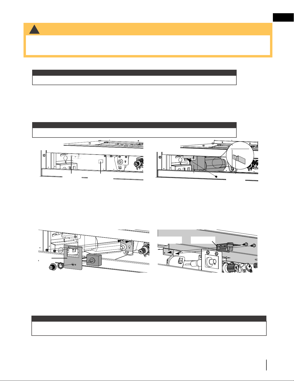
11.0 optional blower installation
• Ensure the appliance is completely cool before starting installation.
• To avoid danger of suffocation, keep the packaging bag away from babies and children. Do not use in cribs,
beds, carriages, or play pens. This bag is not a toy. Knot before throwing away.
!
WARNING
1. Remove the safety barrier by lifting it up and off the appliance.
2. Remove the door from the appliance by releasing the four latches.
3. Attach the two 1/4" connectors (black and white) from the wire harness to the thermodisc.
4. Attach the two 1/4" connectors (black and red) from the wire harness to the blower.
5. Install the clear bumpers (supplied) onto the bottom of the blower to avoid the blower rubbing against the
floor of the appliance.
6. Pivot the blower into the bottom of the appliance, ensuring the gasket remains in place between the blower
and outer shell while sliding the blower against the left side of the outer shell into the blower mounting tab.
Secure in place using one screw (Fig. 1 and 2).
7. Place the control module back into its original position. Ensure the transformer is plugged into the rear outlet
of the electrical box.
8. The variable speed switch (VSS) will need to be disassembled to secure to the VSS bracket for installation.
Place the VSS through the mounting bracket using the lock washer to secure it in place. Take the variable
speed switch knob and install into position (Fig. 3).
9. To install the variable speed swtich, the mounting bracket will first need to be installed. Remove the two
screws securing the piezo ignitor switch bracket in place. Install the VSS mounting bracket ito position then
reinstall the two previously removed screws (Fig. 3).
10. Plug the connector from the variable speed switch to the matching connection of the wire harness.
11. For installation of the thermal disc bracket, bend the tab on the bottom of the firebox 90 degrees. This will be
the mounting tab for the thermal disc bracket (Fig. 4).
12. Bend the thermal disc bracket 90 degrees and secure it to the firebox mounting tab using the two screws
supplied (Fig. 4). Ensure that the thermal disc is in contact with the firebox base and that the wire harness is
properly attached.
13. Plug the power cord from the blower into the electrical box.
note:
It may be necessary to move the control module aside during blower installation (electronic only).
note:
With the zip tie supplied, ensure all wires remain clear of the blower.
note:
The blower is thermally activated, so when it is turned on, it will automatically start approximately 15 minutes
after lighting the appliance and will run for approximately 30 minutes after the appliance has been turned off.
BLOWER
MOUNTING TAB
LOCATION
SCREW
LOCATION
To view a video of This insTallaTion visiT oUR weBsiTe aT: www.napoleonreplaces.com/support/
NOTE: FOR MORE DETAILED INSTRUCTIONS REFER TO YOUR INSTALLATION MANUAL.
aub - aSCent univerSal blower inStallation inStruCtionS
Wolf Steel Ltd., 24 Napoleon Rd., Barrie, ON L4M 0G8 Canada • (705)721-1212 • fax (705)720-9081 • www.napoleonreplaces.com
!
WARNING
ENSURE THE UNIT IS COMPLETELY COOL BEFORE STARTING INSTALLATION.
TO AVOID DANGER OF SUFFOCATION KEEP THE PACKAGING BAG AWAY FROM BABIES AND CHILDREN.
DO NOT USE IN CRIBS, BED, CARRIAGES OR PLAY PENS. THIS BAG IS NOT A TOY. KNOT BEFORE
THROWING AWAY.
W415-1479 / A / 05.09.16
H. Place the control module back into its original position. Ensure the transformer is plugged into the rear outlet of
the electrical box, refer to Figure 2.
I. The variable speed switch (VSS) will need to be disassembled to secure to the VSS bracket for installation. Place
the VSS through the mounting bracket using the lock washer to secure it in place. Take the variable speed switch
knob and install into position. (Refer to Figure 6.)
J. To install the variable speed switch, the mounting bracket will rst need to be installed. Remove the two screws
securing the piezo ignitor switch bracket in place. Install the VSS mounting bracket into position then reinstall
the two previously removed screws, refer to Figure 6.
BLOWER
BLOWER
MOUNTING
TAB
REAR VIEW
A. Remove the screen by lifting it up and off of the appliance.
B. Remove the door from the appliance by releasing the four latches.
C. It may be necessary to move the control module aside during blower installation. (Electronic Only)
D. Attach the two 1/4” connectors (black and white) from the wire harness to the thermodisc.
E. Attach the two 1/4” connectors (black and red) from the wire harness to the blower.
F. Install the clear bumpers supplied onto the bottom of the blower to avoid the blower rubbing against the oor of
the appliance.
G. Pivot the blower into the bottom of the appliance. Ensure the gasket remains in place between the blower and
outer shell while sliding the blower against the left side of outer shell into the blower mounting tab. Secure in place
using one screw, see Figures 4 and 5.
NOTE: WITH THE ZIP TIE SUPPLIED, ENSURE ALL WIRES REMAIN CLEAR OF THE BLOWER.
K. Plug the connector from the variable speed switch to the matching connection on the wire harness.
L. For installation of the thermal disc bracket, bend the tab on the bottom of the rebox 90 degrees. This will be
the mounting tab for the thermal disc bracket, see Figure 7.
M. Bend the thermal disc bracket 90 degrees and secure it to the rebox mounting tab using the two screws supplied,
refer to Figure 7. Ensure that the thermal disc is in contact with the rebox base and that the wire harness is
properly attached.
N. Plug the power cord from the blower into the electrical box, refer to Figure 2.
NOTE: The blower is thermally activated, so when it is turned on, it will automatically start approximately 15
minutes after lighting the appliance and will run for approximately 30 minutes after the appliance has been turned
off.
FIGURE 6
VSS
BRACKET
PIEZO IGNITOR
BRACKET
fiGURe 7
THERMAL DISC
BRACKET
THERMAL DISC
MOUNTING TAB
FIREBOX BASE
BLOWER
BLOWER
MOUNTING
TAB
REAR VIEW
fiGURe 5fiGURe 4
Fig. 1
Fig. 2
BLOWER
MOUNTING TAB
LOCATION
SCREW
LOCATION
To view a video of This insTallaTion visiT oUR weBsiTe aT: www.napoleonreplaces.com/support/
NOTE: FOR MORE DETAILED INSTRUCTIONS REFER TO YOUR INSTALLATION MANUAL.
aub - aSCent univerSal blower inStallation inStruCtionS
Wolf Steel Ltd., 24 Napoleon Rd., Barrie, ON L4M 0G8 Canada • (705)721-1212 • fax (705)720-9081 • www.napoleonreplaces.com
!
WARNING
ENSURE THE UNIT IS COMPLETELY COOL BEFORE STARTING INSTALLATION.
TO AVOID DANGER OF SUFFOCATION KEEP THE PACKAGING BAG AWAY FROM BABIES AND CHILDREN.
DO NOT USE IN CRIBS, BED, CARRIAGES OR PLAY PENS. THIS BAG IS NOT A TOY. KNOT BEFORE
THROWING AWAY.
W415-1479 / A / 05.09.16
H. Place the control module back into its original position. Ensure the transformer is plugged into the rear outlet of
the electrical box, refer to Figure 2.
I. The variable speed switch (VSS) will need to be disassembled to secure to the VSS bracket for installation. Place
the VSS through the mounting bracket using the lock washer to secure it in place. Take the variable speed switch
knob and install into position. (Refer to Figure 6.)
J. To install the variable speed switch, the mounting bracket will rst need to be installed. Remove the two screws
securing the piezo ignitor switch bracket in place. Install the VSS mounting bracket into position then reinstall
the two previously removed screws, refer to Figure 6.
BLOWER
BLOWER
MOUNTING
TAB
REAR VIEW
A. Remove the screen by lifting it up and off of the appliance.
B. Remove the door from the appliance by releasing the four latches.
C. It may be necessary to move the control module aside during blower installation. (Electronic Only)
D. Attach the two 1/4” connectors (black and white) from the wire harness to the thermodisc.
E. Attach the two 1/4” connectors (black and red) from the wire harness to the blower.
F. Install the clear bumpers supplied onto the bottom of the blower to avoid the blower rubbing against the oor of
the appliance.
G. Pivot the blower into the bottom of the appliance. Ensure the gasket remains in place between the blower and
outer shell while sliding the blower against the left side of outer shell into the blower mounting tab. Secure in place
using one screw, see Figures 4 and 5.
NOTE: WITH THE ZIP TIE SUPPLIED, ENSURE ALL WIRES REMAIN CLEAR OF THE BLOWER.
K. Plug the connector from the variable speed switch to the matching connection on the wire harness.
L. For installation of the thermal disc bracket, bend the tab on the bottom of the rebox 90 degrees. This will be
the mounting tab for the thermal disc bracket, see Figure 7.
M. Bend the thermal disc bracket 90 degrees and secure it to the rebox mounting tab using the two screws supplied,
refer to Figure 7. Ensure that the thermal disc is in contact with the rebox base and that the wire harness is
properly attached.
N. Plug the power cord from the blower into the electrical box, refer to Figure 2.
NOTE: The blower is thermally activated, so when it is turned on, it will automatically start approximately 15
minutes after lighting the appliance and will run for approximately 30 minutes after the appliance has been turned
off.
FIGURE 6
VSS
BRACKET
PIEZO IGNITOR
BRACKET
fiGURe 7
THERMAL DISC
BRACKET
THERMAL DISC
MOUNTING TAB
FIREBOX BASE
BLOWER
BLOWER
MOUNTING
TAB
REAR VIEW
fiGURe 5fiGURe 4
Fig. 3
Fig. 4
Loading ...
Loading ...
Loading ...