
Loading ...
Loading ...
Loading ...
W415-2367 / B / 12.09.20
EN
54
finishing
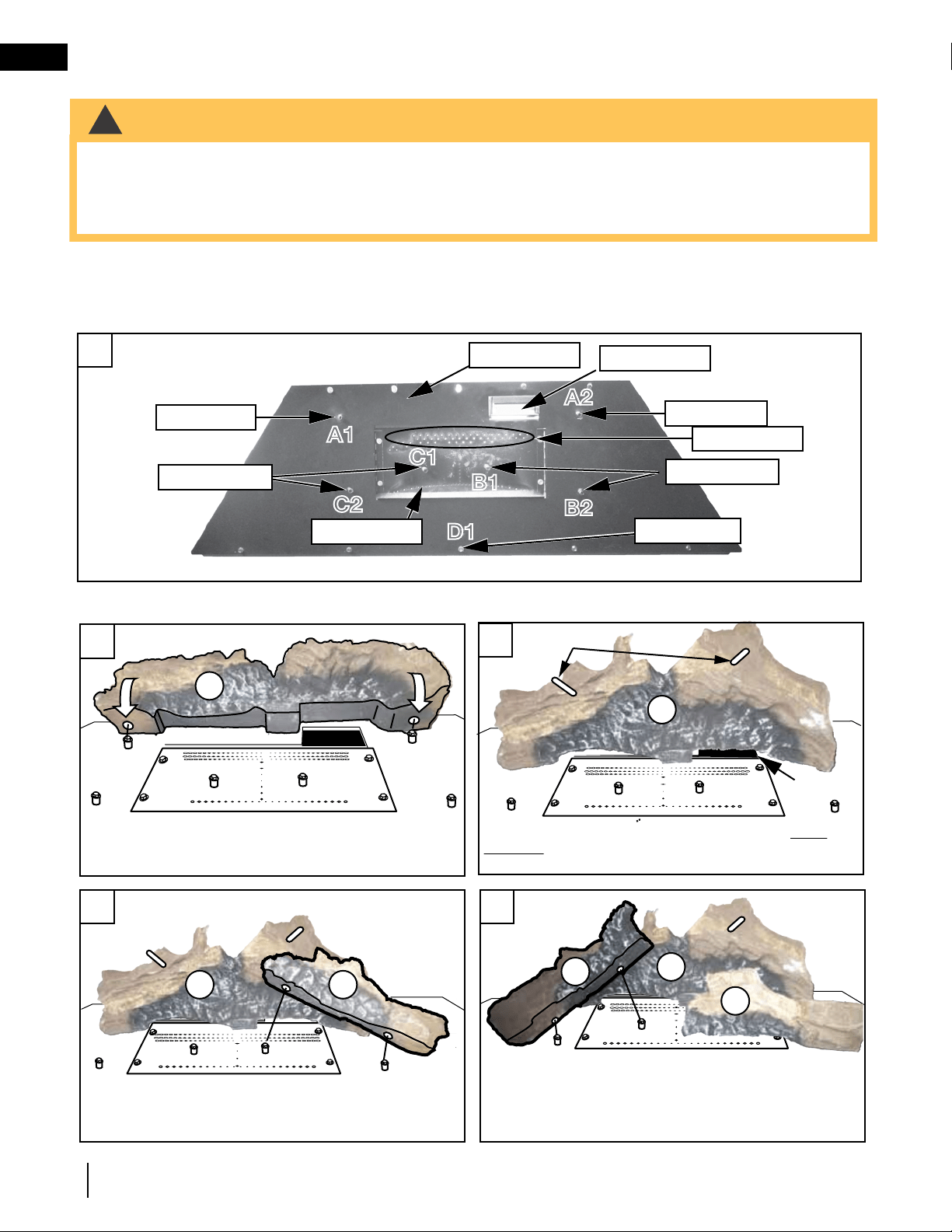
10.7 log placement
!
WARNING
• Failure to position the logs in accordance with these diagrams or failure to use only logs specifi cally approved
with this appliance may result in property damage or personal injury.
• Logs must be placed in their exact location in the appliance. Do not modify the proper log positions, since
appliance may not function properly and delayed ignition may occur.
• The logs are fragile and should be handled with care.
48.1
PHAZER
TM
logs and glowing embers, exclusive to Napoleon, provide a unique and realistic glowing effect that is
different in every installation. Take the time to carefully position the glowing embers for a maximum glowing effect. Log
colours may vary. During the initial use of the appliance, the colours will become more uniform as colour pigments
burn in during the heat activated curing process.
Burner Overview
Place log #2 (W135-0697) onto B1 and B2 located on
the right side of the support tray.
Place log #3 (W135-0695) onto C1 and C2 located on
the left side of the support tray.
Place log #1 (W135-0693) firmly onto A1 and A2
located on the rear of the support tray.
PINS
Ensure log #1 sits flat and does not cover the pilot
opening. Place two pins in the holes located on the
top of log #1.
Stud (Log #1)
Burner Ports
Pilot Opening
Pilot
Opening
A1
C1
C2
B1
B2
A2
Burner Ports
Stud (Log #1)
Studs (Log #3)
Stud (Log #5)
A1A1
B1
B1
C2
C2
B2
B2
A2
A2
Support Tray
2
1
2
3
1
1
1
C1C1
D1
D1
Studs (Log #2)
1
2
3
4 5
Place log #2 (W135-0697) onto B1 and B2 located on
the right side of the support tray.
Place log #3 (W135-0695) onto C1 and C2 located on
the left side of the support tray.
Place log #1 (W135-0693) firmly onto A1 and A2
located on the rear of the support tray.
PINS
Ensure log #1 sits flat and does not cover the pilot
opening. Place two pins in the holes located on the
top of log #1.
Stud (Log #1)
Burner Ports
Pilot Opening
Pilot
Opening
A1
C1
C2
B1
B2
A2
Burner Ports
Stud (Log #1)
Studs (Log #3)
Stud (Log #5)
A1A1
B1
B1
C2
C2
B2
B2
A2
A2
Support Tray
2
1
2
3
1
1
1
C1C1
D1
D1
Studs (Log #2)
1
2
3
4
5
Loading ...
Loading ...
Loading ...